A Control Scheme for a 3
–Phase Power Converter With An Unbalanced
AC Source
N Gautam Vikas*1, P Koteswara Rao2
M.Tech Student, Department of EEE, KIET-II, Kakinada, India.1 Asst. Professor, Department of EEE, KIET-II, Kakinada, India.2
Abstract-Three-stage dc–ac control converters experience the ill effects of power oscillation and over current issues in the event of the uneven air conditioning source voltage that can be caused by lattice/generator shortcomings. Existing strategies to deal with these issues are appropriately choosing and controlling the positive-and negative-grouping streams. In this venture, another arrangement of control techniques which use the zero succession segments are proposed to improve the power controllability under this unfriendly condition. It is inferred that by presenting legitimate zero-grouping current controls and relating circuit setups, the power converter can empower more adaptable control targets, accomplishing better exhibitions in the conveyed control and the heap current when experiencing the lopsided voltage. Fuzzy controller is utilized for the better smoothening of yield wave frames. Recreation results are exhibited to confirm the achievability of the proposed approach in MATLAB/SIMULINK condition.
Index Terms—Control strategy, dc–ac converter, fault tolerance, unbalanced ac source.
I.INTRODUCTION
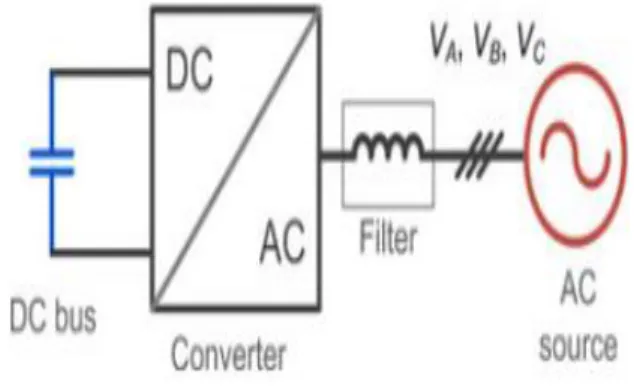
In numerous essential applications for power gadgets, for example, sustainable power source era, engine drives, control quality, and miniaturized scale lattice, and so forth., the three-stage dc–ac converters are basic parts as the power stream interface of dc and air conditioning electrical frameworks. As appeared in Fig. 1, a dc–ac voltage source converter with a relating channel is normally used to change over the vitality between the dc transport and the three-stage air conditioning sources, which could be the power lattice, era units, or the electric machines relying upon the applications and controls.
Since the power gadgets are getting so broadly utilized and getting to be noticeably basic in the vitality transformation innovation, the disappointments or closing down of these
spine dc–ac converters may bring about significant issues and cost. It is turning into a need in numerous applications that the power converters ought to be dependable to withstand a few shortcomings or unsettling influences keeping in mind the end goal to guarantee certain accessibility of the vitality supply. A decent illustration can be found in the wind control application, where both the aggregate introduced limit and individual limit of the power change framework are generally high.
Fig. 1.Typical dc–ac power converter application.
Fig. 2. Grid codes of wind turbines under the grid voltage dip by differentAt the point when the air conditioner source appeared in Fig. 1 winds up noticeably mutilated under flaws or unsettling influences, the uneven air conditioning voltages have been turned out to be one of the best difficulties for the control of the dc–ac converter to keep them regularly working and associated with the air conditioner source. Extraordinary control strategies which can direct both the positive-and negative grouping streams have been acquainted with handle these issues. In any case, the subsequent exhibitions by these control techniques appear to be as yet not acceptable: either mutilated load streams or power motions will be introduced, and accordingly the air conditioner source as well as the power converter will be additionally focused on going with the exorbitant plan contemplations.
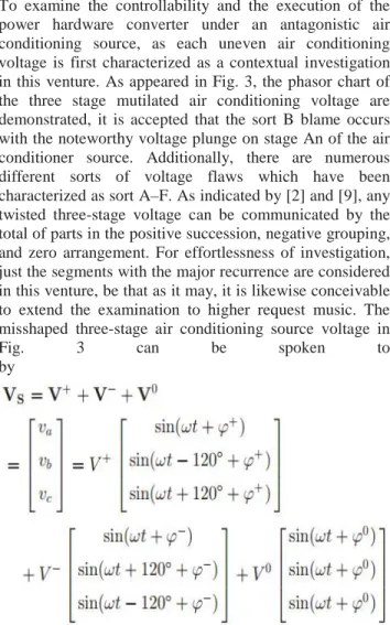
Fig. 3.Phasor diagram definitions for the voltage dips in the ac source of Fig. 1. VA , VB , and VC means the voltage of three phases in the ac source.
This venture focuses to comprehend and enhance the power control cutoff points of a regular three-stage dc–ac converter framework under the uneven air conditioning source. Another arrangement of control systems which uses the zero-succession parts are then proposed to upgrade the power control capacity under this unfriendly condition. Other than the framework mix, the proposed control strategies can possibly be connected under different applications like the engine/generator associations or miniaturized scale matrices, where the uneven air conditioning voltage is probably going to be
displayed; along these lines, the fundamental standard and attainability are for the most part engaged.
II.MODELING OF PROPOSED THEORY LIMITSOF A TYPICAL THREE-WIRE CONVERTER SYSTEM
To examine the controllability and the execution of the power hardware converter under an antagonistic air conditioning source, as each uneven air conditioning voltage is first characterized as a contextual investigation in this venture. As appeared in Fig. 3, the phasor chart of the three stage mutilated air conditioning voltage are demonstrated, it is accepted that the sort B blame occurs with the noteworthy voltage plunge on stage An of the air conditioner source. Additionally, there are numerous different sorts of voltage flaws which have been characterized as sort A–F. As indicated by [2] and [9], any twisted three-stage voltage can be communicated by the total of parts in the positive succession, negative grouping, and zero arrangement. For effortlessness of investigation, just the segments with the major recurrence are considered in this venture, be that as it may, it is likewise conceivable to extend the examination to higher request music. The misshaped three-stage air conditioning source voltage in
Fig. 3 can be spoken to
by
(1)
Fig. 4. Typical three-phase three-wire 2L-voltage source converter
A typically used three-phase three-wire two-level voltage source dc–ac converter is chosen and basically designed, as shown in Fig. 4 and Table I, where the converter configuration and the parameters are indicated, respectively. It is noted that the three-phase ac source is represented here by three winding switch a common neutral point, which can be the windings of an electric machine or a transformer Because there are only three wires and a common neutral point in the windings of the ac source, the currents flowing in the three phases do not contain zero-sequence components. As a result, the three-phase load current controlled by the converter can be written as
(2)
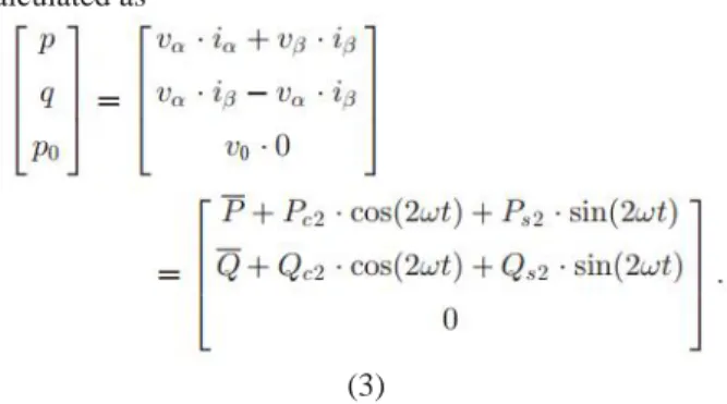
With the voltage of the ac source in (1) and the current controlled by the converter in (2), the instantaneous real power p and the imaginary power q in αβcoordinate, as
well as the realpowerp0 in the zero coordinate can be calculated as
(3)
Then, the instantaneous three-phase real power p3Φ and
the imaginary power q3Φ of the ac source/converter can be written as
(4)
Where P and Q are the average parts of the real and imaginary power, Pc2,Ps2 and Qc2,Qs2 are the oscillation parts, which can be calculated as
(5)
(6)
respectively, to the positive- and negative-sequence voltage/current. Each of the components on the corresponding positive- and negative-dq axis can be written as
(7)
(8) Then, (5) and (6) can be formulated as a matrix relation as
(9) It can be seen from (9) that if the ac source voltage is decided, then the converter has four controllable freedoms (i+d,i+q, i−d ,and i−q ) to regulate the current flowing in the ac source. That also means: four control targets/functions can be established. Normally, the three-phase average active and reactive powers delivered by the converter are two basic requirements for a given application, then, two control targets have to be first settled as
(10) It is noticed that diverse applications may have distinctive necessities for the control of the normal power, e.g., in the power creation application, the dynamic power reference Pref infused to the network is ordinarily set as positive, in the interim the expansive measure of the receptive power Qref might be required keeping in mind the end goal to bolster the matrix voltage [12], [9]. With respect to the
electric machine application, the Pref is set as negative for the generative mode and positive for the engine mode, there might be no or only a couple of responsive power Qref necessities for polarizing of the electric machine. While in most power quality applications, e.g. ,STACOM, Pref is typically set to be little to give the converter misfortune, and a lot of Qref is regularly required.
Thusly, for the three-stage three-wire converter framework, there are just two more present control opportunities left to accomplish another two control targets other than (10). These two including control targets might be used to additionally enhance the exhibitions of the converter under the uneven air conditioning source, which have been by and large researched in [2].However, this venture concentrates more on the assessment of control breaking points and the control conceivable outcomes under the entire voltage plunging range. In the accompanying, two of the most specified control techniques accomplished by three-wire converter structure are researched under the lopsided air conditioning source.
A. Elimination of the Negative-Sequence Current
In the greater part of the matrix coordination applications, there are strict network codes to direct the conduct of the framework associated converters. The negative-grouping current which dependably brings about the uneven load current might be unsatisfactory from the point perspective of a TSO [9]. In this way, additional two control targets which plan to wipe out the negative-succession current can be included as
(11) Translating the control targets in (10) and (11), all the controllable current components can be calculated as
(13) III.CONVERTER SYSTEM WITH THE
ZERO-SEQUENCECURRENT PATH
As can be finished up, in the run of the mill three-stage three-wire converter structure, four control flexibilities for the heap current appear to be insufficient to accomplish palatable exhibitions under the unequal air conditioning source. (Regardless of what blends of control targets are utilized, either huge power wavering or over-burden/twisted current will be introduced.) Therefore, more present control flexibilities are required with a specific end goal to enhance the control execution under the lopsided air conditioning source conditions.
Another arrangement of the converter structure are appeared as demonstrated as the four-wire framework in Fig. 9(a) and the six-wire framework in Fig. 5(b). Contrasted with the three-wire converter structure, these sorts of converters present the zero-grouping current way , which may empower additional present control flexibilities to accomplish better power control exhibitions. It is noticed that in the matrix associated application, the zero-succession current is not infused into the lattice but rather caught in the ordinarily utilized d-Y transformer.
(a)
(b)
Fig. 5.Converter structure with the zero-sequence current path. (a) Four-wire system. (b) Six-wire system.
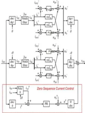
Fig. 6. Control structure for the converter system with the zero-sequence current.
A potential control structure is proposed in Fig. 10, in which an extra control loop is introduced to enable the controllability of the zero-sequence current. After
introducing the regulated zero-sequence current, the three-phase current generated by the converter can be written as
(14)
q in the αβ coordinate,and the real power p0 in the zero coordinate can be calculated as
(15 )
Then, the instantaneous three-phase real power p3Φ and
the imaginary power q3Φ of the converter can be written
as
(16)
It is noted that the voltage and the current in zero sequence only contribute to the real power p3Φ of the converter.
Each part of (16) can be calculated as
(17)
(18)
(19)
Then, the relationship can be formulated to a matrix equation as
(20)
It is noted that unlike the traditional approach in which the zero sequence components are normally minimized, the zero sequence voltage and the current here look like single-phase AC components running at the same fundamental frequency. As a result, the zero-sequence voltage/current can be represented by vectors in a synchronous reference frame in the zero sequence as
(22)
It can be seen from (22) that if the three-phase ac source voltage is decided, then the converter has six controllable freedoms (i+d,i+q, i−d, i−q, i0Re, and i0Im ) to regulate the current flowing in the ac source. That means: six control targets/functions can be established by the converter having the zero-sequence current path. Similarly, the three-phase average active and reactive power delivered by the converter are two basic requirements for a given application, then, two control functions need to be first settled as
(23) So, for the converter system with the zero-sequence current path, there are four control freedoms left to achieve two more control targets than the traditional three-wire system, this also means extended controllability and better performance under the unbalanced ac source. A. Elimination of Both the Active and Reactive Power Oscillation.
Because of more current control freedoms, the power converter with the zero-sequence current path can not only eliminate the oscillation in the active power, but also cancel the oscillation in the reactive power at the same time. This control targets can be written as
(24)
(25)
The power oscillation caused by the zero-sequence currentP0c2 and P0s2 are used to compensate the power oscillation caused by the positive- and negative-sequence currents Pc2 andPs2. When combing (26), (30), and (31), each of the current components controlled by converter can be calculated as
(26)
In order to facilitate the analytical solution, assuming that the d-axis or the real axis in the synchronous reference frame is allied with the voltage vectors in each of the sequence (positive, negative, and zero), then all of the controllable current components with the zero-sequence current path can be solved by
(33)
(27)
IV.FUZZY LOGIC CONTROL
FLC determined by the set of linguistic rules. The
mathematical modeling is not required in fuzzy controller
due to the conversion of numerical variable into linguistic
variables. FLC consists of three part: a. Fuzzification, b.
Interference engine, c. Defuzzification. The fuzzy controller is characterized as; For each input and output
there are seven fuzzy sets. For simplicity a membership
functions is Triangular. Fuzzification is using continuous
universe of discourse. Implication is using Mamdani's
method. FLC block diagram as shown in figure 2.
a. Fuzzification
Membership function values are assigned to the linguistic variables, using seven fuzzy subsets: NB(Negative Big), NM(Negative Medium), NS (Negative Small), ZE (Zero), PS (Positive Small),PM(Positive Medium) and PB (Positive Big). The partition of fuzzy subsets and the shape of membership function adapt the shape up to appropriate system. Input error E(k) and change in error CE(k) of values which is normalized by an input scaling factor as shown in table 1.
Table1:Fuzzy Rules
Fig.4 Input1 Membership function
In this system the input scaling factor is between -1 and +1 has design. The triangular shape of the membership function of this arrangement presumes that for any particular input there is only one dominant fuzzy subset . The input error E(k) and change in error C(k) for the FLC is given as
SIMULINK MODELLING AND RESULTS
5.1 Simulink modeling diagrams:
5.2 Block diagrams of fuzzy logic controller.
Fig.5.3. Simulation of the converter with no negative-sequence current control (three-phase three-wire converter,
Pref = 1 p.u., Qref = 0 p.u.,Id−= 0 p.u., Iq−=0 p.u., VA = 0 p.u., I+, I−, and I0 means the amplitude of the current in the positive negative, and zero sequences, respectively.
Fig.5.4 Simulation of the converter control with no active power oscillation
Fig.5.6 Simulation of converter control with no active power oscillation andno negative sequence (three-phase converter with the zero-sequence current path,Pref= 1 p.u.,
Qref = 0 p.u., Ps2 = 0 p.u., Pc 2 = 0 p.u., id−= 0 p.u., iq−= 0 p.u., VA= 0 p.u. I+, I-, and I0 means the amplitude of the current in the positive, negative, and zero sequences, respectively).
CONCLUSION
In a typical three-phase three-wire converter structure, there are four current control freedoms, and it may be not enough to achieve satisfactory performances under the unbalanced ac source, because either significantly the oscillated power or the overloaded current will be presented. In the three-phase converter structure with the zero sequence current path, there are six current control freedoms. The extra two control freedoms coming from the zero sequence current can be utilized to extend the controllability of the converter and improve the control performance under the unbalanced ac source.
controller is used for the better smoothening of output wave forms. Simulation results are presented to verify the feasibility of the proposed approach in MATLAB /SIMULINK environment.
REFERENCES
[1] F. Blaabjerg, M. Liserre, and K. Ma, “Power
controllability of a three phase unbalanced ac source,”IEEE Trans. Ind. Appl., vol. 48, no. 2, pp. 708–719, Mar./Apr. 2012.
[2] R. Teodorescu, M. Liserre, and P. Rodriguez, Grid
Converters for Photovoltaicand Wind Power Systems. New
York, NY, USA: Wiley-IEEE,2011.
[3] J. Rocabert, G. M. S. Azevedo, A. Luna, J. M. Guerrero,
J. I. Candela, andP. Rodriguez, “Intelligent connection
agent for three-phase grid-connectedmicrogrids,” IEEE Trans. Power Electron, vol. 26, no. 10, pp. 2993–3005,Oct. 2011.
[4] J. W. Kolar and T. Friedli, “The essence of three-phase PFC rectifiersystems—Part I,” IEEE Trans. Power Electron., vol. 28, no. 1, pp. 176–198, Jan. 2013.
[5] J. Hu, L. Shang, Y. He, and Z. Z. Zhu, “Direct active
and reactive powerregulation of grid-connected dc/ac
converters using sliding mode controlapproach,” IEEE Trans. Power Electron., vol. 26, no. 1, pp. 210–222, Jan.2011.
[6] C. Wessels, F. Gebhardt, and F. W. Fuchs, “Fault ride -through of a DFIGwind turbine using a dynamic voltage restorer during symmetrical andasymmetrical grid faults,”
IEEE Trans. Power Electron., vol. 26, no. 3,pp. 807–815, Mar. 2011.
[7] F. Aghili, “Fault-tolerant torque control of BLDC
motors,” IEEE Trans.Power Electron., vol. 26, no. 2, pp.
355–363, Feb. 2011.
[8] Y. Xiangwu, G. Venkataramanan, W. Yang, D. Qing,
and Z. Bo, “Gridfaulttolerant operation of a DFIG wind turbine generator using a passiveresistance network,” IEEE Trans. Power Electron., vol. 26, no. 10,pp. 2896–2905, Oct. 2011.
[9] B. A. Welchko, T. A. Lipo, T. M. Jahns, and S. E.
Schulz, “Fault tolerantthree-phase AC motor drive
topologies: A comparison of features, cost,and limitations,”
IEEE Trans. Power Electron., vol. 19, no. 4, pp. 1108–