http://wrap.warwick.ac.uk/
Original citation:
Howarth, R. M. and Francis, N. D. (1988) Cluster programming language definition and user manual. University of Warwick. Department of Computer Science. (Department of Computer Science Research Report). (Unpublished) CS-RR-125
Permanent WRAP url:
http://wrap.warwick.ac.uk/60821
Copyright and reuse:
The Warwick Research Archive Portal (WRAP) makes this work by researchers of the University of Warwick available open access under the following conditions. Copyright © and all moral rights to the version of the paper presented here belong to the individual author(s) and/or other copyright owners. To the extent reasonable and practicable the material made available in WRAP has been checked for eligibility before being made available.
Copies of full items can be used for personal research or study, educational, or not-for-profit purposes without prior permission or charge. Provided that the authors, title and full bibliographic details are credited, a hyperlink and/or URL is given for the original metadata page and the content is not changed in any way.
A note on versions:
ruResearch
report
125
CLUSTER PROGRAMMING
LANGIJAGE:
DEFINITION AND
USER
]\{ANUAL
Rolf
M
Howarth
&
Nick D
Francis
G.R12s)
The Cluster Programming Language, or CPL, is a high-level array programming language,
used to program the lower levels of the Warwick Pynamid
Machine.
It
is designed to closely match the stmctr.rreof
the architecture,in
order to provide a convenient modelfor
usersof
the machine and to pennit an efficient implementation of the language. Because of the nature
of the architectr,re, the language combines both
SIMD
andMIMD
style parallel programming constructs.In
this
report the languageis
defined,with
several complete examplesof
code being given, and useof an
early interpreter implementation is also described.Department
of
Computer ScienceUniversity
of Warwick
Coventry
cluster
Programming
Language:
Definition
and
user
Manual
Rolf M. Howarth and Nick D.
Francis
Department of Computer Science Universiry of Warwick
Coventry
CV4 7ALE - mail : v I s i @flame .warwick.ac.uk
1.
Introduction
The Cluster Programming Language, or CPL,
is
a high-level array programming language, used.to
program the
lower
levelsof
the Warwick
PyramidMachine
(seebelow).
It
is
designed toclosely match
the
sffuctureof
the architecture,in
order toprovide
a convenient modelfor
usersof
the machine and to permit an efficient implementationof
the language. Becauseof
the narureof
the
architecture,the
language combinesboth
SIMD andMIMD
style parallel programming constructs.In
this
report the language is defined,with
several complete examplesof
code beinggiven.
Useof
an early interpreter implementation is also described.2. Hardware
model
The
Warwick
Pyramid Machinel'2
is
aparallel
architecture designedfor real-time
image andsignal processing,
with
particular emphasis on the transformationfrom iconic to
symbolic datarepresentations.
It
consistsof
several heterogeneous layers: afine
grain arrayof
singlebit
pro-cessors (one per
pixel) for
numeric processing, an intermediatecontrol
layer, and a large grainarray
of
transputersfor
symbolic processing(fig.1). At
eachlevel
the type and granuiariiyof
processor is chosen to match the strucrure
of
the data and the typesof
operation to be performed on it.Symbolic Processing Layer
8x8 .ML\ID transpuler array
Intermediate Level Processors
16x16 MIMD processors, conrolling ppEls
Iconic Layer
86x256 SIMD bit-serial associarive ppFl s
Fig.
I
Warwick
Pyramid MachineFor
low
and intermediate level image processing the arrayof
bit-serial associative PixelProcess-ing Elements (PPELs) is used, arranged in clusters
of
16x16 PPELs eachwith
an associated Inter-mediatelrvel
Processor (ILP)controlling
thecluster.
The
PPELswithin
a
cluster operatein
broadcast
instruction
SIMD mode, but the ILPs themselves are independent, providing localcon-trol.
Together these two levels form a multi-SIMD machine.In
this
documentwe
restrictour
attentionto
the ILP/?PELcluster level
of
the machine, as the transputerlevel
above is programmed separately (in either occam or parallel C) and runs moreor
less autonomouslv.
Host Machine
A
cluster
should ah+'ays be regarded as awhole
-
as a single processor capableof
performing either scalar (ILP)or
vector (ppEL) operarions:2.1
Scalar processorThe
ILP
is
a general purpose 16-bit processor, implemented as a micro-programmable bit-slice processor,with
instnrctions to access the PPEL array wiredinto its instruction
set (onebit
in
themicrocode
word
selects whether the instruction is an ILPor
a PPELinstruction).
The ppEL arrayis
in
effect a co-processor to the main ILp.Each ILP/?PEL cluster can be regarded as a conventionai SIMD machine,
but
the machine as awhole
containsmany
such clusters, andis
capableof
MSIMD operation since each cluster canoperate
independently.
Whenit
is necessaryto
operate several clusters as a single entity, adja-cent [LPs must be synchronisedin
order that PPEL communication across thecluiter
boundaries performs as expected.The
dual-portedILP
data memoryis
shared between the ILP andthe
transputer aboveit
in
thepyramid,
andis
usedfor
communication between thetwo.
The ILP
microcode storeis
also adual-porr
RAM.
The transputer writes toit
at boot time to load either a complete application or a standardset
of
library
routines callablefrom
an
applicationrunning
onJhe
transputers (thislibrary
might include a
multi-bit
multiply
commandinvolving
many hundredsof
onebit
ppELinstructions,
or
aroutine to
perform a Sobel edge detectionconvolution,
for
example).
Theseroutines are usually
written
in CPL, which is then compiled intoILp
microcode.2.2
Vector processorThe PPELs are
simple but
numerous processors, eachwith
abit-serial
N-TJ,7 ffag bits usedfor
storing intermediate results, and (currently) 256 bits of general pu_rpose memory.The
PPELs operatein
SIMD mode (each processor executingthe
sameinstruction
buton
dif-ferent data),
with
instructions broadcast over the array on a commonbus.
ppEL operations may be executedunconditionally
or
be restrictedto
those PPELsin
acluster which
hive
the activeflag
'A'
set. In
addition
the ILP can address anindividual
PPELor
groupof
ppEls
by placing amask on the address mesh, described in the next section.
^lhe 256 bits
of
memoryfor
each processor can be dividedinto
arbitrary sized words (forexam-ple,
it
may be
used as acollection
of
8-bit
grey-scale images,floating point
values, singlebit
flags, and intermediate arirhmetical results of varying lengths).
The
ALU
performsarbitrary logic
functions mapping three input bits totwo
ourputbits.
In eachinstruction cycle
two
source operand bitsi
and 7 (from the flags,from
main memory, orfrom
a neighbouring PPEL) togetherwith
the accumulatorflag
F
are readinto
theALU,
combined by somelogical function,
and two result bits written out: one backto
the F flag and one to anotherdestination
d.
This
operationis
performedby
all
enabled PPELswithin
ailuste,
concurenrly.By
making
useof
theflag
bit
it
is possible to perform simplemulti-bit
operations such asaddi-tion at the rate of one
bit
per instruction cycle.lunction code
16
condaAv 3
src srcJ
4
dest
3
oft sel
3
address
8
Table
1
ppEL insrruction op-codeEach
of
the argument fieldsin
the op-code specifies either oneof
theflag
bits, a valuefrom
theregister
file, or
theoutput from
an adjacent PPEL.Ir
is possiblefor
both source and destinationto
lie
in
the registerfile,
but then they must be the samebit as
there isonly
a single address field. [image:4.595.158.428.632.667.2]all
the PPELscould copy
theF flag
from
the PPELto
their north
into
their
Y
flag,
at the sametime passing their F flag on to the sourh).
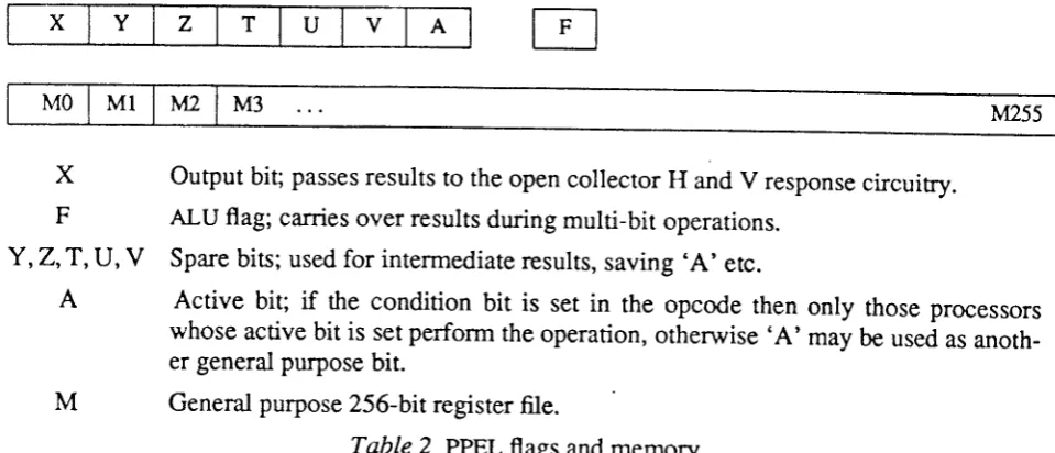
X Y
z
T U V AM0lMllM2lM3
t\ns5X
F
Y,Z,T,U,V
A
output
bit; passes results to the open collectorH
andv
response circuitry. ALU flag; carries over results duringmulti-bit
operations.Spare bits; used
for
intermediate results, saving'A'
etc.Active bit;
if
the condition
bit is
setin
the
opcode thenonly
those processors whose activebit
is set perform the operation, otherwise'A'
may be used as anoth-er genanoth-eral purposebit.
General purpose 256-bit register file.
Table
2
ppEL flags and memory2.
3
PPEL/ILP communicationThe PPELs are connected together
in
theform
of
a meshwith
8-way nearest neighbourconnec-tivity.
Data can be readin
from
these neighbour linesduring
normal ppEL instruction cycles as mentionedearlier. In
addition to this there are several mechanismsfor
communication between the PPELs and the ILP, utilised by special instructions at theILp
level.Associative feedback to the
controlling
tLP is providedvia
the PPELX
ourputflag.
An opencol-lector wired-oR
circuit
gives a some/none response over the wholecluster.
At
thesami time
a fast adder tree provides the ILPwith
a countof
the number of respondingppEls in
a cluster.To facilitate
reading datainto
andout
of
the
array the PPELs are also connectedon
agrid
of
addressinglines
with
a wired-OR responsecapability.
These lines, running alonga1
rhi
rows and columnsin
a clusterwith
an encoder at the two edges, enableindividuaipixels
to be locatedquickly
(fiT.2).
The ILPs also have direct access to the lines,giving
them theability
to establishwhether more than one PPEL is responding.
V address
Vmask
H address
M
[image:5.595.60.540.77.283.2] [image:5.595.68.530.516.675.2]The lines are
bidirectional,
with
the horizontal andvertical
directions being connolledby
the lrand
v
condition
bits in
the PPELinstruction
word. This
allows
theILp
to directly
address anindividual
PPELor
grcup of PPELs, using the clusterlike a
RAM.
Another application is to write on one and readfrom
the other, enabling a single column say, and then reading the 16 bits fromthat column
in
parailel.2.4
ILP|ILP
andlLpltransputer
issues'fhe
scenarioin
which
ILP programs are runis
thatof
procedures being calledfrom
thecontrol-ling
transputer.This
might be achievedby
meansof
aimall
operatingiystem
kernel running oneach ILP and
implementing
a procedurecall
protocol
via
thedud-pJned
RAM sharedwith
thetransputer.
When
anILP
procedure finishes,control retruns
to
this
kernel,which
makes any result availableto
the Eansputer and awaits the next procedurecall.
An
alternative approach isto
have the transputerdirectly
set up a stack framein
theILp
memofy, asif
acall
were being carried out by the ILP, and then load the ILP instruction counterwith
the start address.For reasons
of
simpliciry,
the sameprog:lm
(ie. set
of
callable procedures) is loaded intoall
theILPs.
There
is
no
requirement, however,that
different
transputers shouldcall
the
samepro-cedure together, which
permia
the ILps to run independently.When necessary' synchronisation benveen ILPs is performed
via a
number ofopen collector sync
channels.
The
basic merhanismis
that those ILPswishing to
synchronisefirsi
all
pull
the sync channellow, ie.
inactive.
They can then performindividuil
operations. When an ILp finishes,it
stops
forcing
the channellow
and idles,waiting
for
it
to become activeagain.
Eventually more and more ILPswill
finish
and become ready,until
the last one goes ready, when the sync linefloats high and
all
the ILps may continue together,in
sync.There are several sync channels available,
permitting
independent groupsof
ILps to synchronisethemselves. One transputer in the system acts as master, allocatinglhis^resource (sync channels) on request
to
those transputers wishingto
synchronisetheir
ILps.
Typically
oneoi
the puo-"-tersin
a transputer to ILP callwill
be the numberof
a sync channel to use.io
p'o,r.,
against thepossibiliry that one
of
the ILPsin a
group wishing to synchronise becom.rrr.dy
before the otherILPs have
initialised
the sync operationby
pulling
theline
low,
thecontrolling
transputer irselfforces the sync channel inactive
until
it
receives confirmation thatail
theILrs
using that channel haveinitialised.
Note that we have
only
describei thelow
level mechanismof ILp
synchronisation.Responsibil-ity
for
breakingdown
an application into tasksfor
the ILps to perform concurrently and-decidingwhen
synchronisation needsto
take place,and
betweenwhich
ILps,
lies with
the
o*rpu,ri
array'
The master transputer plays a key rolein
this, making use, amongst other things,of
a glo-bal some/none and response count over the entfue ILP a:ray (an extensionof
the circuiury
wiitrin
each cluster),
but
a discussionof
how the transputerlevel is
prograrnmed lies outside the scopeof
this document.An
alternative meansof
achieving purelylocal
synchronisationis by
using rheILp
toILp
com-municationprimitives
'send'
and'receive'.
These use a rendezvous mechanism, whereby nwo3.
CPL
language
definition
When
using CPL
theprognmmer's model closely
matchesthe hardware.
Scalar operations,including
ILP integer arithmetic,function calls
and loop control, use a simple conventionalsyn-tax
similar
to Pascal orC. ln
additionto this
standard core, though, thereire
corn-ands
tojer-form
avector
operationin
parallelover
all
the PPELsin
the cluster, aswell
as operandsto
iead datain
and outof
the PPEL array which can be usedin ILp
expressions.Because there are these two
different
kindsof
processorwithin
a cluster,it
is helpful
always tomake a clear distinction between ILP and PPEL instructions
in a
CPLprogram.
For example, the'tl'
instruction
is the familiar conditional at the ILP level,while
'vehere'is used to restrict a ppELoperation to certain pixels
within a cluster.
These operations, as well as calculations and assign-ments and soon,
ars analogous at thetwo
levels, butif
the syntaxof
the language wereto
hidethe distinction
between similar operationson different
processorsit
would
unaouUteaty lead toconfusion.
We
therefore
innoduce the basicILP
and PPEL operationsin
separate sections,followed
by
adescription
of
interfacing between thetwo.
In
thefollowing
definitions we use bold for reserved wordsor
symbols, and italic for other syntax elements. Example code is in a sanserif font.A
program
consistsof
statements,usually
oneper line,
though
a
semicoloncan be
used to separatemultiple
statements on the sameline.
Spaces betrveen tokens are needed whereambi-guities might
otherwisearise. Extra
spaces andblank
lines areignored.
Everything benveen a'#'
and the endof
a line is ignored as a comment.A.
Conventional
scalarprogramming
This
section
describes thoseILP
operationswhich
are
familiar from
normal
sequential,pro-cedural languages.
3.1
ruP
variables and expressionsILP
variables are
16bit
signedintegers. They
are referredto
by
symbols, consisringof
upper andlower
case alphabetics and the underscore character, which must be declared before use:intt
ilpvar,
...An ILP
expression may consist ofjust
a single term, either an ILP variable, an integercons*nt,
afunction
return value, or some other special term (such as'any',
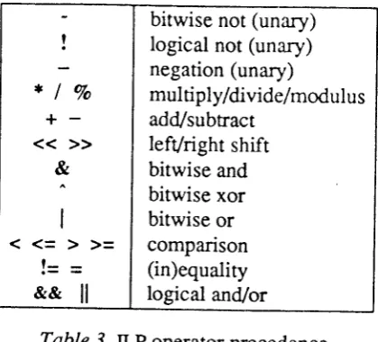
see 3.8). These basic terms canalso be combined using the arithmeric and
logical
operators givenin
table3
(basedon
thoseof
the C languageT). Parentheses may be used to alter t-h"pt...d"nce
of operatorsin an
expression.Constants are usuaily
in
decimal,but may
bein
binary
or
hexadecimalif
precededby ,0b'
or'0x'
respectively.Expressions may be evaiuated and rhe result assigned to an ILp variable:
tlpvar
:=
ilpexprFor example,
int: average,
x
average := (count(
)+x)P
Arrays
of
integers can also be defined. Conventional square bracket notation is used, eg.int:
a[to]
x
:= a[2]-
|
bitwise nor (unary)| | l^-:^^t -^^ /---\
!
|
logical not (una-ry)I
negation (unary)*lVo
lmulriplyidivide/modulus
+
-
|
add/subtract&
|
bitwise and^
I
bitwisexor
|
|
bitwise or<=>>=
lcomparison
!=
=
|
(in)equatity&&
ll
I
logical and/or Table-t
ILp
operator precedence3.2
Control
constructsVarious
conml
constmcts areavailable.
Remember thatin
general many rl-ps arerunning
thesame program
concurently,
soin
a conditional branchor
loop
some ILps can beexecutinf
one branchwhile
some arefollowing
theother.
See section 3.9foinores
on synchronising rheoi.ru-tion
of multiple
ILPs.The syntax
of a
conditional branch isif
expr
then
... stmts ... lelse
...
stmts ...1endif.
If
thereis only
one statementin
the body'endif'
be omitted,for
example ifx<0
thenx
:=-x
The simplest way to implement a loop is
with
the'for..next'
statement. The two expressions areevaluated once at the start to give the lower and upper bounds
of
theloop.
On each iteration theloop variable
is
incrementedby
one,or by
the
step sizeif
given (which
may be negative, inwhich case the loop counts down),
until
it
reaches the upper bound.for
var
= €xpt to expr [step expr)... stmts ...
next vcr.
There are
two
formsof 'while'
loop, the standardwhile
expr d,oendwhile
# carry out body of loop
if
expr is trueand
with
thecondition
at the end, so the loop is always carried out at least oncedo
while
expr.A
generalisedloop
in
the mannerof
Ada
existstoo,
where the
condition,or
conditions,can
occur at any
point
within
theloop.
The
'exit'
statement causes ajump to
the endof
the loop, and can also be used to break outof 'while'
or
.for'
loops.# carried out
if
erpr
is true# carried out
if etpr
is falseit
may be placedon
the sameline as the
,if',
and the [image:8.595.195.405.45.235.2]loop
exit lwhen exprl
enOloop.
#
exit
when condition is true3.3
Program
structure:functions
A
CPL program consistsof
a numberof
function or
proceduredefinitions.
As
in
C
thereis
nodistinction
between functionsreturning a value
and procedureswhich do
not.
Unlike
C
how-ever, there isno
'main'
procedure where execution always starts, sinceit
is up to thecontrolling
transputer to initiate execution
of
code on a cluster by calling any procedureit
choses.Functioni
may
be called by the Eansputeror from
within
another CPL function, but the syntax remains the same.func name (
fparameter list]
)...body of
funuion
.../return
expr) # optional (integer)retun
valueendfunc.
The parameter
list
specifies the typeof formal
parameters being passed to the function, eg.func sobel (int: n; bitplane: image, result).
Variables
definedin
the parameterlist or within
a function arelocal to
thatfunction.
All
vari-ables, both
ints
and bitplanes (seebelow), that
are declared outsideof
afunction
are static andglobal,
however, and their value is accessiblefrom within
any function.B.
PPELarray programming
3.4
Bitplanes
The basic data types operated on by the PPELs are single
bits.
Apartfrom
the 8 flag bitsX,
y,
Z,T,
(J,V,
A
and F, each PPEL has a numberof
bits of main memory, currently 256 bits,addressed
M0... M255.
Contiguous bitsof
this memory are frequently grouped together formulti-bit
opera-tions.
For
example,Ml0,l1,l2,l3
may be used as an accumulator, containing one4-bit
number.Data is stored least significanr
bit first
(ie.Ml0
= lsb,Ml3
= msb).Since
it
is inconvenientto
keep trackof
these locations byexplicit
address, the language allowsnamed PPEL variables. The statement bitplan e: flag, image[al
for
example, allocates a singlebit
(in
each PPEL across the plane) to atoken/ag,
and 8 contigu-ousbits to
a tokenimage. In
this example imagemight
be placed at M10..M17; thiswould
then be accessed usinginnge
to refer toall
8 bits,image[]l
to refer toMll,
imaget3..Sl to refer to the3 bits
Ml3..M15
etc.While it
is possible to use explicit memory addresses when special circumstances demandit,
andalso to access
all
the flag bits, their use is to be discouraged as no knowledge should be assumedabout
which
locations the compiler mayuse.
The flagsX,
Y
andZ
arc freely availablefor use
in
a CPLprogmm
(whereX
is
usedto
signal a responsefrom
the PPELto
theILp), but
the orhers are usedby
the compilerfor
PPEL expression evaluation, as carry and overflow flags, to save the stateof
A,
and so on.Bitplanes
are allocated automaticallyon
a PPEL datastack.
When a CPLfunction
returns, thememory
used as bitplaneswithin
that function
is
freedagain. Internally a
bitplaneis
really
apointer to
some PPEL memory and a countof bits.
Normally a'bitplane'
statement allocates theappropriate
numbr of
bitsin
PPEL memory,initialises
themto
zero, and associates the address and sizeof
the bitplanewith
the symbolname. An
alternative use is just to use the addressof
anexisting bitplane, by placing the bitplane at a given address using
,='.
lsigned/
bitplane: name[[sizs]l
[=ppelvar],
...For example,
if
we assume that free PPEL memory (the stack) currently starts at M100, the state-mentbitplane : im ag e[a] =tt t 6, buffe r[B], m sb=buffe r{ 71, lovv{dl=buffe r, fl ag
would
resultin
thefollowing
birplanes being definedimage
M16.,M23buffer
M100..M107msb
M107Iow
M|00..WA3flag
M108.As
bitplanes are aUocateddynamically their
size may begiven by
an ILP expression calculated at run time.Bitplanes
arenormally
unsigned, unlessa
bitplane declaration
is
precededwith
the
reservedword
'signed'
in
which case the most significantbit
is used as a signbit
andtwo's
complementarithmetic is used.
3.5
PPEL expressionsCalculations over the array are described by PPEL expressions. When an expression is evaluated
it
returns a bitplane value which may then be assigned to a PPEL variable or flag:ppelvar
<-
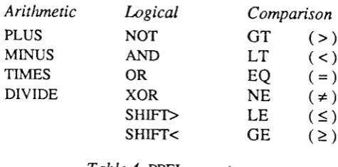
ppelexpr.PPEL expressions consist
of
bitplanes and numeric constants combined using variousarithmeti-cal
andlogical
operators. Since ILP and PPEL expressions operate on different data types adif-ferent set
of
operators is used, but thefunction
and precedence rulesfor
these operators isidenti-cal
to
the corresponding ILP operators (refer to table 3).Aritfunetic
PLUS MINUS TIMES
DIVIDE
I-ogical
NOT
AND
OR XOR SHIFT> SHIFT<
Comparison
GT
(>)
LT
(<)
EQ
(=
NE
(*
LE
(<
GE
(>
Table
4
PPEL operarorsBecause PPEL calculations
involve
variable numbersof
bits, the precision used when evaluating an expressionis
derivedfrom the
sizesof
the birplanes usedin
the expression. Theminimum
number
of
bits to guafimtee correct evaluation is used.If
the number of bits in the variable being assignedto
differs
from
thatof
the expression being evaluated, the resultis
truncatedor
null-padded / sign-extended accordingly (and the F flag is set
if
the result is too large tofit).
To
ensure that PPEL expressions can be evaluated to the appropriate precision the sizeof
abit-plane is always associated
with
the bitplaneitself.
During
a function call the size of a bitplane is passed alongwith
its address (bitplane parameters are always passed by reference), which allowsone
to
pass bitplanesof
arbitrary size to afunction,
andto write
functions which work correctly whatever the precisionof
their parametersare.
The 'sizeof(bttplane)'
operator can be used to [image:10.595.176.414.455.573.2]This default number
of
bits used when evaluating expressions can be reduced by selecting a sliceor
subsetof
a bitplane using the square bracketnotation.
Start and end bits(with bit
0 =-lsb) arespecified, where a missing end means take the range up to the end of the birplane.
A
PPEL'constant' is
constant acrossthe
cluster.
It
may be a decimal,binary
or
hexadecimal constant'or
it
may be given by the valueof
an ILP expressionif
the'$'
rype conversion operator is used (see3.8).
PPEL constants need not necessarily be fixed at compiie time, so longai
a sin-gle value to be used across the whole cluster is given at theILp
level.Examples
of ppeL
expressionsnum
<-
image MTNUS goffsetflag
<-
NoT (Z
AND (num[o..a] GT 4))num
<-$(countO +
l)
# ILP expression3.6
Accessingneighbouing
ppEls
To
access datafrom
oneof
the8
adjacent neighbours the notation d,irzreg can be usedin
ppELexpressions,
where
dir
is
one
of
N,NE,E,sE,s,sw,w,Nw.
It
may also
be
of
the
form
'Voilpexpr', in
whic.h case the ILP expression must evaluate to a numberin
the range0..
7 whichis used as the direction (where N is 0, NE
is
l,
etc.)num
<-0
num[0..q]
<-
)bl0l
10num[t..] <-
1xAimage
<-
N:imagetemp
<-
"/"i:num# Decimalconstant
# Binary constant
# Hexadecimalconstant
#
shift entire image southby
onepixel
# read from neighbour givenby
variable 'i,#
setallYs
in column 4#
get
PPEL at position (4,7) to respond ifA
is
set Onefrequently
wants to perform an operation overall
the neighboursof
a ppEL, so the special notationassoc_op
all:bitplane
can be used
in
expressionswith
oneof
the operators SUM (or pLUS), AND, OR and XOR, eg.flag
<-
ORall:X
is
equivalentto
the much more cumbersome (and less efficient, becausein
theformer
case thecompiler is able to produce optimised code)
flag
<-
N:X OR NE:X OR E:X OR ...To combine the four direct neighbours
only
(N, E, S andw)
use,ail4'.
3.7
Conditional
operationsThe PPELs are SIMD processors and the same instruction
is
broadcastto
all
theppEls within
acluster.
Simple conditional
operations,restricting
a PPEL insrructionto
thoseppEls
that have the conditionflag
'A'
set, can be performed by appending'?'
to the instruction, eg.num
<-num
PLUS|
?This
will
increment the bitplanenun
onjust
those PPELs whose conditionbit
is
set.
Note thatthis instruction
will
still
take the same numberof
cycles as an unconditional instruction evenif
no PPELs are enabled and executeit.
By
default conditions act on theA
register, but an instruction can also be conditional on the Hor
V
mask (describedin
2.3).
The'?'
modifier
may be followed by the letters A, H orV
to indicatethe condition or conditions, eg.
hmask:= Oxl0
Y<-
I
?Hvmask:=
0x80X <_
1 ?HVATo
rnake useof
conditionals easier the'where'
instructionresricts
executionof
a blockof
codeto
those PPELs that satisfy theconditional
expression(ie.
those whereexpr
evaluatesto
a non-zero value)where
eryr
... .rPnr.t ...
Ielsewhere ... stmts...l
endwhere.
For example
where (suM all:data EQ 0)
data
<-
0 endwhere.# thin isolated points (those with 0 neighbours)
'Where'
statements can be nested, progressively restricting the set of activeppEls.
There are two variations on the
'where'
statement that may be used to restrict operations to asin-gle PPEL (specified by its address)
or
to an area of PPELs (specified by rwomaik
values)respec-tively.
rvhereaddr address
address is
in
the range 0..
nz-r,where
n is the sizeof
a cluster,typically
16. rvheremask lmaskvmaskhmask and vmask are placed on the horizontal and vertical mesh lines (see 2.3).
A
'where'
statementwith
an 'elsewhere' clauseis
implementedby
first broadcasting theinitial
block
of
instructionsto
the PPEL :uray, thentoggling
the appropriate conditionbit
andbroad-casting the 'else'
portion.
Again,
thepoint
should be made that executiontime
for
a
.where'conditional
is
the
same evenif
no
PPELs are enabledto
perform
oneor
the other
block of
instructions.C.
Other
aspects of CpL3.8
Interface
between ILP andppELs
There are a number
of
specialterns
and predefined functions that can be usedwithin ILp
expres-sions to access the PPEL cluster.The horizontal
and vertical mesh lines are accessedvia
two
ILP registen, which are referred tofrom
CPLusing
the reservedwords
'hmask'
and
'vmask'.
Any
valuewritten
to
these ,vari-ables' is placed on the mesh when a'?H' or '?V'
conditional modifier is used.If
they are readin
an expression then data is readfrom
themesh. Similarly,
'any'
is a read only pseudo variable,yielding
a Boolean valuewhich is
true(ie.
1)if
any PPELsin
the cluster currenrlv have theirX
responder
bit
set, or false (0) otherwise.The function
'firstX0'
returns the addressof
the respond.ing PPELwith
lowest address,or
-l
if
there are no responders. This uses the output
of
thepriority
encodersinfig.2
and works bypick-ing
the first row,
enabling
that
row
and then
selectingthe first
column
with
a ."rpond.r.
'count(
)'
returns a countof
the number of respondersin
the cluster.The function 'read(cddress,&ppelvar)'can
be
usedto
read datafrom
a
particularppEL
(ineffect
this
worksby
using'whereaddr' to
select the PPEL, gettingit
to outputits
data onto the some/none bus one bit at a time, and accumulating the valuein
an ILp register).To pass
datafrom
theILP
to the PPELs normal PPEL instructions are usedbut
with
the parame-ters specifiedindirectly
by ILp expressions.The
'$'
type casting operator converts antLP
expressionto
appEL numeric
constant, and the'Vo'
opetalor converts an ILP expressionto
a bitplane address.No
assumptions should be madeas
to
how
a pointer
to
a
bitplane
is
storedat
the ILP
level (information
stored includes the address and sizeof
the bitplane, whetherit
is
a flagor
in
main PPEL memory, andis
signed or unsigned). Instead,'&'can
be appliedto
any bitplane toyield its
address and sizein
thisinter-nal
format.
Ttre
'Vo' operator shouldonly
be applied to expressionspreviously
obtained using'&'.
'Vo'
is
also used to specify a direction indirectly, astn'Vod:bitplane'.
As a
convenientabbrevia-tion, one may
omit
the'&'
whenreferring
to directions, so'for
d =N
to W step2,
canbe used to step through thefour
direct
neighbours,for
example.
Theloop
variable can be used as a sub-script directly (where N=0,NE=l,
E=2 and so on) to accumulate a result over neighbours.For symmetry
with
'read()'
thefunction 'write(address,.&ppelvar,ilpexpr)'is
provided, thoughit
is directly equivalent to whereaddr (address)ppelvar
<-
g(ilpexpr) endwhere.Also
usefulin
this
context
areseveral
'compiler
constants'which give
details
of
the
currentimplementation:
Isize
(the numberof
ILPs acrossin
the machine),Myaddr
(the addressof
this ILP, from 0 to Isizexlsize-
I
), and Psize (the size of a cluster, inppEls
across).3.9
ILP
synchronisation andcommunication
The basic mechanism
for
ILP synchronisation and communication is as describe din
2.4 .In
normal
usethe
transputersdetermine
which
ILPs should synchronise themselves and passdown the numbers
of
one or more sync channelsfor
the ILPs touse.
To perform synchronisationin
a cPL program this sync channel mustfirst
be initialised, usingsyncon n # channel n allocated by transputer.
The
actuai synchronisationof
ILPs using that sync channel then occurs oncethey
haveall
exe-cuted the instnrction
s)'nc
# wait until ail ILps are ready.ILP
to
ILP communication
is via
occam-like
channels, andis
indicated
by
the reserved word'chan'.
Thuschan c !
ilpexpr
chan c ?
ilpvar
where c is one
of
thefive
(predefined) channelsN,s,E,w
andup.
For example,chanE?x
chan UP !
(result+l)
dir:=
chanE
chan dir
!
1
# indirect channel specification (This useof '?'
should not be confusedwith
ppEL conditional operations.)# send word # receive word
4.
References
1.
R.M.
Howarth,
"A
heterogeneouspyramid
array
architecrurefor
image
understanding,,,Research Report 115, Dept.
of
Computer Science, University ofWarwick,
Diember
19g7.2.
G.R. Nudd,R.M.
Howarth, T.J.Atherton, N.D.
Francis, G.J.Vaudin,
andD.W. Walton,
,.A
heterogeneous architecture
for parallel
image processing,"
inProc.
IgSguK
Information
Tech-nology Conference, pp.495-499, Swansea,
July
1988.3.
C.C. Weems and S.P.Levitan,
"The
Image
UnderstandingArchitecture," in proc.
DAR1AImage Understanding Workshop, pp.483-496, February 19g7.
4.
S. Pass,"The
GRID parallel computersystem," in
ImageProcessing
System Architectures,ed. J.
Kittler &
M.J.Duff,
pp. z3-3s, Research studies press, 19g5.5.
M.J.B.
Duff
and T.J. Fountain (editors),Cellular
Ingic
Image Processing, Academic press,New
York,
1986.6.
D.E.
Reynolds and G.P.Otto,
"CLIP
'Image
ProcessingC'
UserManual", Report
No. g2/4,Image Processing Group,
University
Colleget
ondon, 19g1.7.
B.W.
Kernighan andD.M.
Ritchie, The C Progratnming Language, prenrice-Hall, 197g.Appendix
I
Example
1:
Sobel edge detection# Pertorm the following convolution for horizontatedges
#
-t-2-1
# 000
# 121
# and the same thing vertically, then combine the fwo as the sum of mods.
# lllustrates the use
of
'sizeof
to work with arbitrary precision data.func sobel (bitplane:image, resu It)
# Store intermediate results with sufficient precision
bitpl an e : parti al[sizeo f(i m ag e ) +2], te m pfs i ze of (i m ag e) +21
temp[t..]
<-
image
#bmp <-
image.2+E+Wtemp
<-
temp PLUSE:image
pLuS W:imagetemp
<-
S:temp MTNUSNtemp
where
F
# negate if negative toget
absolute vatuetemp
<-
0 MINUS temp endwherepartial
<-
temp
# partial is usedto
savelGxl
temp[t..]
<-
image
#
Same thing verticailytemp[O]
<-
0
# clearediniiatty
butnow
containsjunk
temp<-
temp pLUSN:image
pLtJS S:imagetemp
<-
E:temp
MINUS W:temp whereF
temp
<-
0
MINUS tempendwhere
# Return
lGxl
+ lGyl, scaled to fit sizeof
resuttre su lt
<-
(partial PLUs
temp) sH t FT> (s +sizeof (i mag e) - sizeof (re s u tt))endfunc sobel
Example
2:
Edgefollowing
#
This function follorys edges, returninga
tist ofthe
addresses ofedge
points#
withina
cluster. lt ignoresany
intersections.func simple_edge_follow (bitplane: lmage) bitplane: Mark, Edge, Result[a]
int: addr, th, dir
sobel(lmage,
Result)
# catculateg-bit
Sobetth :=
lfiyssljold(Result)
# calculate threshold Edge<-
ResultGf
$tn
#
Set Edgeif
Resutt>
th Mark<-
0toop
X
<-
Edge AND (suM ail:EdgeEa
r)
#
setx
if #neighbours= r, ie.
it,s an endpointexit when
lany
# exit toop if no endpointsin
this ctusteraddr:=
firsXo
whereaddr addr
Mark
<-
|
*
pick an endpointto
start fromendwhere do
addr := firstX(
)
chan
Up
!addr
# output one point to the Symbolic layerwhere Mark
clear
Edge
#
reset the point wehave
read endwhereX
<-
Mark
# output markto
its neighboursF
<-
oRall:X
#
tes;t if any of the neigi'tbour inputsare
set
X
<-
Edge AND FMark
<- X
while any
endloop
# continueuntilthe data
has been read out endfuncExample
3:
Mean and
maximum
# Calculate local means and maxima within a cluster simultaneously, one bit
at
# a time, by iterating starting with
the
most significant bit.int: mean,
max
#globalvariables
toreturn
resultsfunc meanmax (bitplane: image) bitplane: flag
int: total,
i
flag
<-
1
X this ppELnot
less than max (so far)total := 0 lfl1X
l=
0for i = sizeof(image)-1 to 0 step
-l
X
<-
image[il
total :=
Z'total
+ count()
#
lf
flag=Q l've already been discounted as max, so don,t outputX
X
<-
X
AND flagfTte,X
l=
2'max
+any
#
lf
some pixelin
thecluster
has thisbit
set (any) butmy
#
bit
isn't set(X:0)
then I can't be a maximalpixel
if any then flag
<-
X
#if
,any &X=0,then
reset flagnext
i
mean := total/(Psize'Psize)
endfunc
#
This code fragment illustratesthe
,al!' notation:bitplane:
Unbrs[e]Nnbrs
<-
0
#
IJse a 3-bit accumulator to count the neighboursfor dir = N to
NW
#
iterate over the g neighboursNnbrs
<-
Nnbrs ?LUSl"dir:Edoe
next
dir
# is equivalent to
Nnbrs
<-
suMall:Edge
# GUM is a synonymfor
pLUS)Example
4:
Guarded
edgethinning
# Elliman and Mahmood's thinning algorithm (adapted by N.Francis) # incorporates extensive guarding to prevent over-erosion
# From D.G.Elliman and A.Mahmood "Towards faster and more shapely thinning,,,
#
in Parallel Processing forcomputer
vision and Display, Leeds,,lan
i gaafunc thin (bitplane: edge_bit)
bitplane: count[a], init_coun{ql, number_se{al, init_flag
bitplane: neighbour[B], clear_flag, temp, guard[a], any_guard
int:d
# Get all neighbours bits and count them
ford=NtoNW
n e ig h b o u r[d]
<-
lod : e dge_bit
nert
d
number_set
<-
SUM all:edge_bit# Count number
of
consecutive bits set in neighbotur init_ffag<-
1
#
lnitiatise flagsclear_flag
<-
0ford=NtoNW
where neighbour{d}
count
<-
count ?LUSI
# ifbit
set inc countwhere init_flag
init_count
<-
init_countpLUs
I
# ifbit
set & not had a zeroyet
endwhereelsewhere
count
<-
0
# if bitnot set
clear countinit_flag
<-
0
# and init-fhg
endwhere
clear_flag
<-
clear_flag AR @ountEe
number_set)next
d
#
At
thispoint init-count
holds the number of consecutive bits setat
start # count holds the #consecutive at the end of the word# clear_flag is set if we found 'number_set' consecutive bits at
any
stage# Now check for wrap around
where ((init_count 7LUS count)
Ee
number_set) clear_flag<-
l
endwhere
#'clear-flag'is
set ifallthe
neighbouring bits are consecutive.#
We don't want to thin solid regions or endpoints though... where (number_set EQ 8) OR (number_set LT 3)clear_flag
<-
0 endwhere# Generate guard signals according to tabte 2 of Eiliman and Mahmood
temp
<*
(number_set EQ3)
AND clear_flagwhere
(temp AND
neighOour{Nwl)
# S neighboursguard[NW]
<-
|
endwherewhere
(temp AND
neighbour{Swl)guara[Sw]
<-
t
endwhere#4or5neighbours
temp<-
(number-set
GTg)
AND_(number_set LT6)
AND ctear_ftagwhere (temp _AND neighbourfNW] euo neighbour[SW])
guard[Sl
<-
l
endwhere
where
(teqp
AND neighbour{SW| AND neighbour[SE])guard[W]
<-
1endwhere
temp
<-
number_set EQ6
# 6 neighbourswhere
(temp
AND NoTneighbour{N})
;guara[Sl
<-
|
endwhere
where
(temp
AND NOT neighbour[NE])guara[SW]
<-
|
endwherewhere
(temp
AND NOTneignboufEl)
guard[w]
<-
|
endwhere
temp
<-
number_set EQ7
# 7 neighbourswhere (temp AND NOT neighbourfN|) guard[S]
<-
1endwhere
where (temp AND NOT neighbourfEfi
guard[W]
<-
|
endwhere
where
(tenp
AND NOT neighbourfNE])guard[S..W]
<-
7
#
set guards S, St4/and
Wendwhere
where (temp AND NOT neighbourfSEl)
guard[W..Nw]
<-
3
#
set guards W, NW andN
guard[N]
<-
1endwhere
# Check for any neighbour guards
any_guard
<-
0ford=NtoNW
any-guard
<-
any9uard
OR%d:guard[(d+4f/"8]
# d+4 calculates opposite directionnext
d
#
lf
clear_flag and no guards preventing me then ctear mypixel
where (clear_flag AND NOT
anyjuard)
edge_bit<-
0endwhere
endfunc thin
Appendix
II
An
earlier implementation:
User manual
for
the
'sim' interpreter
Introduction
Initially
the clusterlevel
of
thewPM
architecture was simulatedby
meansof
an interprerer foran early version
of
the CPL language, running as a single user process underUnix.
This versionof the language, now referred to as CPL-1, differs from the current
definition
in
several ways.There are
various
syntactic changes,chiefly
at the PPEL level,reflecting the fact
thatin
CpL-l
these operations were at a
lower level,
corresponding much moreclosely
to
the hardware (seethe section on
'Low
level PpEL operations' below).The PPEL memory model that CPL-1 assumed
differs slightly from
the current versionin
thatit
has
two
banksof
128bits
each(P
andQ),
rather thana
single registerfile
(M).
This
has theadvantage
that
in
a
single PPEL instructiontwo bits
from
the registerfile
can be accessed, butonly
if
they
have painstakingly been setup to
use corresponding locationswithin
thep
ande
files.
This
idea was eventually dropped as not being general purpose enough, aswell
as rather cumbersome to use.The
original
implementation included
several implementarion dependentVo
and
debuggingstatements
('load'
and
'save', 'display',
'print'
and'verbose',
all
describedbelow).
Someol
these may reappear
in
future implementationsof
CPL-Z, as and when appropriate.The
original
user manual,
giving
details
of
the
languageand
how
to
use
the
simulator,
is appendedbelow.
Mostof it
does not make very exciting reading unfortunately, andit
is mainlyof historical interest.
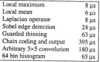
Tacked on the endof
this appendix, however, are sometiming
results andsample oufput,
which
may beslightly
more readily accessible.The'sim'
interpreter
An
emulatorof
the PPEL and ILP levelsof
thewPM
architecture has been implemented,in the
form
of
an interpreterfor
the Cluster Programming Language.A
definition
oi
the language, as implemented by sfin,is
given below.This implementation
of
CPL isonly
suitablefor
SIMD or multi-SIMD processing over the whole image array, asit
would
need to be usedin
conjunctionwith
some higherlevel
language topro-vide a complete programming system for image understanding tasks. Its main use is
for
interac-tively developing and experimenting
with
low level algorithms.Srrn
is written
in
C
underUnix,
and runson both
Vaxes andSuns.
It
currently
implements128x128
or
256x256 PPELs.It
may be used interactivelyor from
ascript
of
CpL commands. Imagesto
be processed are loaded and saved as Unix files, and may also be ourput on a graphicdisplay.
A
basictiming
metric
is
providedby
displaying the executiontime
of
a program in clock cycles.CPL-I
language summaryA program consists
of
statements, one perline.
Each line has theform
command
argl
arg2 ...where these
keyword
and argument tokens are separatedby white
space charactersor
commas.If
a token containsa
spaceor
commait
must be quoted(with
a singlequote).
Blank
lines andlines starting
with
a
'#'
ate ignored as comments. The commands are summarised below, withmore detailed notes
on
someof
the commands and theform
of
parametersgiven
in
subsequent sections.I/O
and simulatorcontrol
loadfilename
n regsave
filename
n regdisplay
n reg posnIlabel]
verbose
[+-]mask
arg,
...printf
str,arg,
... showdrg,...
bitplane
namefisizd|
[-reg],
...unsync
end
Basic PPEL operations
op
ij
d[addr]
[
?]
repeat
n opij
d addr[
?]Multi-bit
PPEL operarionsdefaults
to
1.clear
[n]
dest[
?]
set[n]
dest[
?]
complement
In]
dest[
?]copy
[n]
src dest[
?] copyc[n]
src dest[
?]add
n src dest[
?] sub n src dest[
?]
subfrom n
src dest[
?]scale
n
src dest const[
?]accumulate
n
src dest const[
?]compare
nregl
reg2[
?]rvhere
[l]src
whereaddr
addresswheremask
hmask vmask ... stmts ...lelsewhere
... stmts ...1endwhere
The
following
instructions may affect theX
or F flag bits.of
a
calculation
is
greater
thanZn-l
or
less than
0.# load
or
save an imagein
a Unix file# output PPEL array contents # set simulator output level
# display ILP variables or arguments # formatted
# display
intemal
simulator variables etc.# allocate a named array of ppEL memory
# force unsync'd operation
# terminate
prognm
# single
bit
operation#repeat op i
j
daddr++
n timesThe flag F is set when the result
For
non-arithmetic
operations n# dest
e-
0 # dest<- all
1's # dest(-
not dest # destF
src # deste-
not src# dest
<-
dest + src, F<-
overflow# dest
<-
dest-
src,F
<-
overflow# dest
(-
src-
dest,F
<-
overflow# dest
(-
constx
src,F
e-
overflow# dest
<-
dest + constx
src, F<-
overflow# test
&
set:X <-
(regl=reg2),
F<-
(regl>reg2)#
A <-
src,A
(-
not src# access a single PPEL by address 0..255
# ac.cess PPELs using
roVcolumn
masks#A<-notA
PPEL
conditional
operationAny
PPEL operationcan
be restrictedto
acrive PPELs (thosewith
bit
A
segif
a
,?'
isappended
to the instruction.
Alternatively,
oneof
the
forms
of
'where'can
be used to makeall
the PPEL statements in a block conditional onA.
During
awhere block anindivi-dual operation can be made unconditional by appending a
,!'.
'Where'
statementsmay
not be nested as such, but successive where's can be used topro-gressively
restrict
the setof
active PPELs, up to the occurrenceof
an'endwhere'.
(Foithe
secondand
subsequentwhere's'A(-A&src',
though
'!'
can
still
be
usedto
force'A
(-
src'.
Theold
value ofA
is not saved.)ILP operations
if
arg
then
# conditional (multi-)branching... stmts ... lelse
... stmts ...1
endif
for var
= argto
arg[step
arg]
# BASIC-style for..next loop... stmts
...
#
(unsyncedif
args aren't constants)next
[var]
#
var may be givenfor
extra checkingrvhile arg
do
# standardwhile
loopenOrvnite
do
# ditto, but loop is carried out at least once,rt
ii.
urgIoop
# generalised loopexit ftvhen
arg/
# can also break outof 'while'
or
'for'
loopsendloop
var ;= arg [binop
arg]
# assignment to ILp variablesync
# resynchronise the ILpsLow
level PPEL operationsThe PPEL
ALU
performs anyof
the 216logic
functions mapping threeinput bits
(i,7
and F) totwo oufput
bits
(d and F), so the function opcode therefore has 16 bits (2 oulput bitsfor each of
8different inputs).
For
example, the codefor the'add with carry'function is
0001011001101011,which
may becalculated by reading successive pairs out
of
the last two columnsin
thetruth
table below.Table
5
Truth tablefor'add
with
carny'There are
two
waysof
specifying this function opcodein CPL. It
may be givenexplicitly,
as anumber consisting
of
eight base-4 digits precededby
an'ar'
sign (eg. @01I2l2Z3
for
theexam-ple