A thesi:3 presented :f::or t:he dre:'gree of
Doctor: of Philosophy in E:lt"'ctricaJ. Enginel":ci.nc; in the Un:i.ve:rs:L·ty of Canterbury,
Chrin tch urch, T'k~w Zec:lla.nd .
by
R.M. LEWITT B.E. (Hans)
Contributions to Image Reconstruction
, . , Some Ud ng _, vJhos e 'l'ntth convina 1 d a:/; S-ight we find, .
'l'ha-1; g·ives us back ·the .Image of our• Mind:
ABSTRACT
The problem of image reconstruction from indirect
measurements is considered. Reconstruction methods for the
following types of measurement are presented in detail: (a) Radiant intensity at the image plane of the
transmission electron microscope.
(b) Radiant intensity of X-ray diffraction from
paracrystalline and fibrous macromolecular specimens.
(c) Projections which may be incomplete in linear extent,
as well as sampled and finite in number.
Image reconstruction from measurements (a) and (b) is affected by the phase problem.
It is shown how:
(a) Off-set holography might be achieved in the electron
microscope when examining a crystalline specimen or an aperiodic specimen deposited on to a crystalline
substrate. A diffraction plane mask selects one of the
diffracted beams from the crystal to act as the
holographic reference. Microscope aberrations may be
compensated after reconstruction from the hologram. An optic?J,l simulation of the·process is reported. (b) Under certain conditions it is possible to deduce the
continuous diffraction pattern of a molecule from measured crystal structure factor intensities.
Theoretical results are derived for the diffraction
from generalised helix-like structures. A recently
consistent with much of the available X-ray data.
(c) Preprocessing of projection data may be effected
efficiently \vhen the data are measured with a fan beam of radiation.
(d) Usefn.l imaqes may be' reconstructed from projections ,.,hich are incomplete in the sense that they are
"hollow" or "truncated".
'l'he. :rno0.:Lfied back-projection method of image reconstructiou .:Ls analysed in detail. "Hollow" and ·"truncated" projections are defined to be projections
which have their inner and outer parts missing, respectively. Theoretical cow:>iderations show that unambiguous
reconstruction is possible from hollmv but not from
truncated projections. Practical methods are presented
which preprocess the incomplete projections so that
reconstructions can be obtained from them using the modified
back-projection method. Examples showing reconstructions of
a test object ~rom computer-generated incomplete projections
ACI<N OWLE DGEMEN'E S
I am especially grateful to my supervisor,
Professor R.H.T. Bates, for his encouragement and inspiring guidance in all aspects of this work.
Dr T.M. Peters of the Department of Medical Physics, Christchm~c:lL f.-iospital, has generously given me the benefit of his practical experience of image reconstruction from 'projections, and his insight into this problem has also been
most valuable .. Illuminating discussions with Dr P.R. Smith
of the Biozentrum der Universit~t Basel are gratefully
acknowledged. The Department of Radiotherapy and Oncology,
Christchurch Hospital, generously allowed me extensive use of their digital computer, which was of considerable
assis·tance in my research.
I am grateful to my former fellow research students, Drs M.J. McDonnell, P.T. Gough and D.J.N. Wall, for helpful discussions and advice in the initial stages of my work.
The comments of my colleagues in the Department of Electrical Engineering, and G.R. Dunlop in particular, have been most useful.
I would like to thank visiting university staff for their coruuents and encouragement, particularly Dr S.R. Keown of the Department of Metallurgy, University of Sheffield, U.K. (crysto-holography) and Prof. W.M. Boerner of the
Department of Electrical Engineering, University of Manitoba,
grateful to Dr G.A. Rodley of the Department of Chemistry, University of Canterbury, for suggesting that electrical engineers might be able to contribute to the verification of his novel proposals for the structure of the DNA molecule.
The financial support of a postgraduate scholarship from the University Grants Committee and the assistance of the New Zealand Post Office are gratefully acknowledged.
TABLE OF CONTENTS
ABSrrRACT
ACKNOWLEDGEMENTS GLOSSARY
PREFACE
CHAPTER 1:
1 • 1 1 • 2 1.3
1.4
1. 5
1 • 6
1.7
1 . 8
1 • 9
PART 1
IMAGE FORMATION AND HOLOGRAPHY Introduction
Waves and Particles Image Formation
1 • 3. 1 The Radiation Pattern 1.3.2 Image Formation by Lenses Holographic Imaging
1. 4. 1 Principles of Holography 1.4.2 Formation of Holograms
Image Formation in the Electron Microscope 1 . 5. 1 Phase Contrast Imaging
1.5.2 Image Improvement
Holography and the Electron Microscope New Proposals for Electron Holography
1 • 7. 1 1. 7. 2
Introduction to Crysto-holography Biprism Crysto-holography
Dual Image Formation in the Electron Microscope Crysto-holography
1.9.1 Principle of Off-Set Holography
1. 9. 2 1. 9. 3 1 • 9. 4 1. 9. 5
1. 9. 6
Crysto-holography
Method of Successive Interferograms Image Processing 1
Light-Optical Simulation Discussion
l< ... igures
Page
i i i
Page CHAPTER 2: U1AGE PROCESSING
2.1 Introduction
64
64 67 67 2.2 Image Enhancement and Restoration
2.3
2.4
2.5
2.6
2. 2. 1
2.2.2
The Inverse Filter
Processing of Images Formed with Incoherent Radiation Processing of Images Formed
with Coherent Radiation
2.3.1 The Phase Problem and
68
72
Inverse Filtering 72
2.3.2 Phase Retrieval Using Image and
Diffraction Plane Intensities 75 2.3.3 Processing of TwO Images
Recorded with Different Defocus 79 2.3.4 Processing of Two Complementary
Single Sideband Images 82
Reconstruction of Images Formed with Incoherent Radiation
2. 4. 1 2.4.2
Astronomical Interferometry X-ray Diffraction
A Technique for Processing X-ray Diffraction Data, with Application to the S·tructure of DNA
2.5.1 2.5.2 2.5.3 2.5.4 2.5.5 2.5.6 2.5.7
Introduction: The Structure of DNA Rationale
Theoretical Properties of Diffraction Patterns Interpolation behl-:'18:":1 Structure Factoru
Observed Diffractlon by B-DNA Theoretical Diffraction by a Double-Helical Molecule Comparison of Theory
and Observation
Processing of DNA Molecular Models: Theoretical Diffraction from
Helix-Like Structures 2. 6. 1
2.6.2
2. 6. 3 2.6.4
Introduction
The Fibre Pattern
Continuous Representations of DNA Models
Diffraction from
Filamentary Structures
2.6.5 2.6.6
Diffraction from
Continuous Structures Conclusions
Tables and Figures
PART 2 CHAPTER 3: INTRODUCTION TO IMAGE
RECONSTRUCTION FROM PROJECTIONS 3.1 Review
3.2 Notation and Basic Results
3.3
3.2.1 3.2.2
The Projection Theorem
Projection Expansions Using Angular Fourier Series
Projection Measurement Using a Fan Beam of Radiation
3. 3. 1 3.3.2 3.3.3
Projection Representations Conventional __ Diverging-Ray Projections
Effect of Angular Offset of Detector
3.3.4 3.3.5 Figures
Diverging-Ray Data Processing Results and Discussion
CHAPTER 4: IMAGE RECONSTRUCTION BY MODIFIED BACK-PROJECTION 4. 1 Introdu'ction .
4. 2 Modified Back-Proj ec·tion 4.3 Interpolation Considerations 4.4 Finite Length Filters
4.5
4.6
4 • 4 • 1
4.4.2
Filter Truncation and Computation Finite Filter Implementation
Back-Projection of Sampled Data 4.5.1 Exact Interpolation 4. 5. 2
L~ • 5 • 3
Approximate Interpolation in ~
Approximate Interpolation in
¢
ConclusionsTables and Figures
Page CHAPTER 5: IMAGE RECONSTRUCTION FHOM INCOMPLETE
PROJECTIONS: 'rHEORE'l'ICAL CONSIDERA'riONS 209
5.1 Introduction 209
5.2 Preliminaries 209
· 5.3 Hollow Projections 211
5.4 Truncated Projections 213
5.5 Errors in Reconstruction
from Incomplete Projections 218
Figures CHAPTER 6:
6. 1 6.2 6.3 6.4 6.5 6.6 6.7
PRACTICAL IMAGE RECONSTRUCTION FROM INCOMPLETE PROJECTIONS Introduction.
Rationale
Simple Completion of Projections 6 .-3. 1 Trunca·ted Projections 6.3.2 Hollow Projections
Projection Consistency Conditions Consistent Completion of Projections 6. 5. 1 Hollow Projections
6.5.2 Truncated Projections Projection Theory and
Alternative Methods of Reconstruction 6. 6. 1
6.6.2 6.6.3
Projection Basis Functions Reconstruction using
Zernike Polynomials Reconstruction using
In·tegral Equation Ir-1vers:i.on Conclusions
Tables Figures Plates
CHAPTER 7: CONCLUSIONS AND SUGGESTIONS FOR FURTHER RESEARCH
7.1 Crysto-holography and X-ray Diffraction from DNA
7.2 Image Reconstruction from Projections BIBLIOGRAPHY (Image Processing) ..
GLOSSARY
Unless indicated otherwise, the symbols and
abbreviations used'in this thesis have the meanings given below. Wherever possible, two functions which are a
Fourier transform pair are denoted by upper and lower case forms of the same letter.
arc DNA eqn exp FFT Fig. i
I (x)
Jl
J (x)
m
m
rom, nm
Angstrom uni·t of length: 1
A
=
10-10 mprefix denoting inverse trigonometrical function. deoxyribonucleic acid.
equation.
exp (x)
=
ex where e is the base of natural logarithms.fast Fourier transform (algorithm) . figure.
i 2
= -
1modified Bessel function of th8
first kind, order Jl and a.r9ument x • ordinary Bessel function of the
firs·t kind of order m and argumPnt x .
as stiliscript to a periodic function of an angular variable: the mth order coeff~cient in the
angular Fourier series expansion of the function. respectively 10-3 and 10-9 metres (m)
P~u,v)
(x) Jacobi polynomial of order n, argument x andsinc(x)
T (x)
n
x,y,z a, 13
e
t;,,
n
1T p E
*
*
®lxl
sin (1Tx)
'IT X
Chebyshev polynomial of the first k~nd,
order n and argument x .
Chebyshev polynomial of the second kind, order n and argument x .
Cartesian coordinates in image space Cartesian coordinates in Fourier space Dirac delta function
Neumann factor. £
=
ln n
=
0=
2 nf
0angular coordinate in image space Cartesian coordinates in image space rotated by ¢ from x, y .
3.14159 •••
radial coordinate in Fourier space summation
angular coordinate in Fourier space, and angLe at which projection is measm:ct,.
(superscript) complex conj U'J?.te. If a and 13
*
are real and w =a+ iB then.~ =~-iS.
(in line) convolution
f(x)
*
g(x)= Joo
f(u) g(x-u) du-oo
correlation
f*(x) ® g(x)
= Joo
-oo
*
f (u) g (x
+
u) du0
< (_~)
> ( >)
00
0
(superscript) angular degree, 1
=
n/180 rad. (superscript) estima·te of a functionis less than (or equal to) is greater than (or equal to) is approximately equal to
(superscript) truncated (e.g. projection, spatial filter or associated function. N.B.
p
is cutoffspat~al frequency).
(superscript) hollow (e.g. projection or associated function) .
PREFACE
Reconstruction of images from measured data is important in a wide variety of scientific applica·tions. For example, a reconstructed image may depict a molecular structure or i t may be a map of the brightness temperature distribution of a giant star. Because an image is a
representation of an object or physical system, the
formation, processing and interpretation of images is an activity common to many scientific disciplines which are otherwise unrelated.
The most familiar images are those formed directly by optical instruments, using visible light reflected or
transmitted by an object. In many applications in which an image is required, we can make only Jndirect me~surements by probing the object with invisible radiation or by
interpreting such radiation emitted :by :~t .. Often, the measurement data are not in a form suitable for interpret-ation, but are related to the required image in a known way. The aim of image reconstruction is to p:coces::: the data to form ari image and so facilitate the interpretation of the measurements.
In a significant number of applications, the measured data correspond to the Fourier transform of the required
image or to projections of it. In both cases, recons·truction of the image is straightforward when the data set is
practical methods for improved acquisition and reliable processing of incomplete data is a continuing challenge to workers in applied science and engineering. This thesis contributes to the development of both the acquisition
and the processing aspects of image reconstruction, with particular emphasis on important applications in electron microscopy, molecular structure determination and medical cross-sectional imaging (tomography).
'l'he Fourier transform of an image is complex-valued, requiring both modulus and phase for its complete
specification. Often, however, only data relating to.the modulus of a complex-valued image or image transform can be recorded, hence a "phase problem" arises. There are tttlo approaches to circumvent the phase problem. The first
approach is to form an image in such a way that the complete modulus/phase information is encoded in a recording of
modulus only. This approach to data recording and image reconstruction is known as holography. · ~fuen holography is not possible, the alternative approach attempts to process the incomplete data, relying heavily on independent knowledge to supplement the data.
In Chapter 1, the principles of conventional and holographic image formation are described briefly and related to the formation of images in the electron microscope. A survey of past attempts to implement holography in the electron microscope is given. A new proposal known as "crysto-holography" (Bates and Lewitt
already aroused the interest of other researchers, and two modifications of the original proposal have been published
(Greenaway and Huiser 1976, Pozzi 1977). The modified proposals are discussed, together with other Felated methods to collect·data appropriate for subsequent image reconstruction.
This work arose out of discussions with
Dr S.R. Keown, a. visiting lecturer in the Department of Mechanical Engineering, University of Canterbury. His particular interest is the analysis of metal structures using the electron microscope. Encouraged by Dr Keown and Prof. Bates, I began optical experiments aimed at improving Dr Keown's microscope images. Shortly after, the idea of crysto-holography occurred to Prof. Bates. We then
developed detailed proposals which I simulated in the optical laboratory.
A new structure for an important biological molecule called DNA has been proposed by Dr G.A. R.odley of the
Department of Chemistry, University
oZ
Canterbury (Radleyet aZ. 19 76) • The phase problem impedes i_he .i:1terpretation
of all X-ray diffraction patterns, but this incompleteness is compounded in the case of DNA diffraction aata because of difficulties in preparing regular crystalline specimens.
The first four sections of Chapter 2 present a brief survey of image processing, with particular reference to procedures which overcome the phase problem. The remainder of Chap·ter 2 presents new methods for the processing of
conventionally accepted structure of DNA with the alternative structure proposed by Dr G.A. Radley.
Dr Radley's interest in the structure of DNA was initially aroused by discussions with C.H. Rowe, a senior technician in the Department of Electrical Engineering,
University of Canterbury. Dr Radley conceived a new
possible· form for the structure, and he built detailed molecular models, assisted by his s·tudent R.'S. Scobie.
Prof. Bates and I together developed a theoretical analysis of diffraction from tl1e proposed structure and I developed
computer programs to obtain numerical results. The basic
theory of the method for processing the X-ray diffraction
data is principally due to Prof. Bates. Our final
presentation of ·the method incorporates techniques which were found to be necessary as a result of my computational work.
The conventional X-ray imaging process results in a
shadow picture of the internal structure of an object. The
image which is recorded by the film is a summation of all the structural details of the object, an~ is said to be a
1
'proj ection" of it for the corresponding angle of view.
When only a thin cross-sectional. slice of cL ·i.:hree-dirt)ensional object is irradiated, a one-dimensional projection (or
profile) is measured. A number of such projections may be
The theory of image reconstruction is well-known for the ideal case when the form of the projections is given completely. This happens only when projections are known as continuous functions spanning the whole cross sec·tion and are known for the continuum of all possible angles of view.
In practice, projection data is necessarily
incomplete because only a finite number of projections can be measured. Part 2- of this thesis analyses a practical method for reconstruction from a finite number of sampled projections, an~ develops new theoretical results and
practical methods for reconstruction from projec·tions which have their inner or outer parts missing.
Chap·ter 3 in·troduces the subject matter of the following chapters and refers to related work on image
reconstruction from projections. Notation and basic theory are presented and a convenient graphical technique for
representing sampled projection data is described. This representation is used to develop a method for the
preprocessing of projection data measured using a fan-shaped beam of radiation.
The techniques presented in Chapter 3 are being incorporated in a low-cost X-ray tomographic system to assist radiotherapy tr'eatment planning at Chris·tchurch Hospital. This project is directed by Dr T.M. Peters and
Mr J. J. rrai t of ·the Medical Physics Department. In the
and its associated electronics was continued by J.M. Clark as an M.E. (Master of Engineering) project. Mr Clark is presently completing this work as an employee of the Medical Physics Department. In section 3 of Chapter 3, my ideas on organising the dat~ from a fan-beam detector are combined with Peters' concept of the offset detector, and a technique
(from the literature) for representing the data.
Chapter Ll discusses an important practical method for reconstruction from a finite nur~er of sampled
projections. This method is known as modified
back-projection. The effects of various approximations inherent in the method are described in detail. Use of the projection representation introduced in Chapter 3 gives new insight in·to
--the practical performance of --the modified back-proj~ection
method and shows how i t may be improved.
The wor~ presented in Chapter 4 was motivated by the
development of an efficient computer program to' perform back-projection. The program was written by Dr Pe·ters, and I became interested in the factors \'7hiclt affect the quality of images obtained using this method of reconstruction. The analysis and conclusions are my own, J:-,ut discussions with Dr Peters improved my understanding of the effects of
interpolation and the work on spatial filters incorporates suggestions by Prof. Bates and G.R. Dunlop.
Incompleteness of projection data is particularly severe when some parts of the projections are not measured.
and i t is shown that unambiguous reconstruction is possible from hollow, but not from truncated projections. A
theoretical analysis is given for the error which is introduced into a reconstructed image when hollow or truncated projectiqns are treated as though they are complete. The prac·tical use of these results is pointed out.
The formulation and detailed analysis of the problem of reconstruction from hollow and truncated projections has been developed jointly by Prof. Bates and myself. Dr P.R. Smith drew our atten·tion to ·theoretical solutions of the hollow projection problem. Dr Peters contributed ·to our tmderstanding of the ambigui·ty inherent in reconstruction from truncated projections, and presented the preliminary results at a Topical Meeting sponsored by the Optical Society of America.
Practical methods for reconst~cuction froin hollow and truncated projections are presented in Chapter 6. The
incomplete projections are preproces~8d su that useful
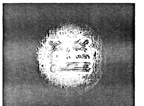
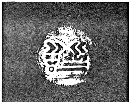
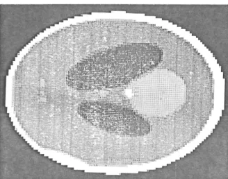
reconstructions can be obtained from th8m using the modified back-projection method. Examples shmnng reconstructions of a test object from computer-generated, incomplete projections are used to demonstrate the effectiveness of two distinct preprocessing techniques.
projections and for the detailed theoretical results which explain i·ts effectiveness. These results are closely allied to the work in Chapter 4. In the second preprocessing
method, I unify and extend some of the results published by Smith, Peters and Bates (1973) and develop a practical method for reconstruction from hollow projections. These ideas also lend support to the conclusions of Chapter 5 relating to reconstruction from truncated projections.
Chapter 7 concludes the thesis and presents
suggestions for further research and development rela·ted to this work.
During the course of this research, ·the following papers have been published or submitted for publication:
P.R. Smith, T.M. Peters, R.M. Lewitt and R.H.T. Bates
"Aspects of Image Reconstruction by Fourier Me·thods". In: Technical Digest, Image Processing for 2-D and 3-D Reconstruction from Projections. Topical
Mee·ting, Stanford, California, Aug. L~-1, 1975.
(Optical Society of America, Washington D.C. 1975). Paper ThA4, 1-4.
R.H.T. Bates, R.M. Lewitt, T.M. Peters and P.R. Smith "Image Reconstruction from Incomplete Projections".
Ibid., paper WA2, 1-l~.
R.H.T. Bates and R.M.· Lewi·tt "Crysto-holography".
Optik 411 (1), 1-16, Dec. 1975.
G. A. Rod ley, R.
s.
Scobie, R. H. T. Bates and R. M. r,ewitt "A Possible Conformation for Double StrandedPoly-nucleotides".
G.A. Redley, R.S. Scobie, R.H.T. Bates and R.M. Lewitt "A Possible Conformation for Double Stranded
Poly-nucleo·tides".
Proceedings of the National Academy of Sciences of the U.S.A. 73(9), 2959-2963, Sept. 1976. R.H.T. Bates, R.M. Lewitt, C.H. Rowe, D.P. Day and
G.A. Radley "On the Structure of DNA". Journal of the Royal Society of New Zealand 7(3) Sept. 1977.
T.M. Peters and .R.M. Lewitt
"Computed Tomography with Fan Beam Geome·try" Journal of Computer Assisted Tomography
'1(4) Oct. 1977.
R.M. Lewitt and R.H.T. Bates
"Image Reconstruction from Projections: I: General Theoretical Considerations". Optik (submitted).
R.M. Lewitt, H.H.T. Bates and T.M. l)eters "Image Reconstruc·tion from Projections: II: Modified Back-projection !Jlethods". Optik (submitted).
R.M. Lewitt and R.H.T. Bates
"Image Reconstruction from Pro~ectlons:
CHAPTER 1
IHAGE FORMATION AND HOLOGRAPHY
1.1 INTRODUCTION
Our principal methods of obtaining iQformation about the external world make use of radiation emanating from a physical system. The radiation may be either generated within the system or transmitted or reflected by i t . An "image" is a representation of a physical object or
sys·tem which is formed or derived from such radiation. The mos·t common sensing devices are op·tical
instruments (e.g. eyes, microscopes, telescopes) ·that form images directly using visible light~ Images are often formed using electromagnetic radiations other than light. The radiation may alternatively be a form of mechanical wave motion (e.g. sound, ultrasound, se1sm1c w~ves) or i~ may
consist of moving atomic particles (e.9. beams of electrons, protons or neutrons) •
This chap·ter briefly describes the formation of images of objects using electromagnetic radiation and
high-energy electron beams. The wave-like nature of moving atomic particles is discussed in sec·tion 1 • 2. The
propagation and interference of waves are considered in section 1.3, leading to a description of image formation by the optical lens.
explains how one wave may reconstruct another when i t illuminates a recording of their interference pattern. Section 1.5 shows that the formation of high-resolution images in the electron microscope involves interference of electron waves and is thus a form of holography.
Holography was originally envisioned as a means of extending the useful resolution of the electron microscope; the
techniques which have been employed are summarised in section 1.6. Section 1.7 is devoted to a new proposal called "crysto-:holography" (Ba·tes and Lewitt 1975). The detailed development given in the original paper is presented in section 1. 9, including the results of a light-optical simulation of the proposed method.
Greenaway and Huiser ( 197 6) use ·fhe ·crysto-holography
proposal as a basis to develop an approach to holography in the electron microscope which makes use of two differe-nt recorded images. Their ideas and other related·methods are discussed in section 1.8.
1 . 2 WAVES AND PARTI.CLES
In 1864, Maxwell predicted eleri~romagnetic wave
propagation more than twenty years before Hertz's researches (in 1887) gave experimental verification. In a similar way Louis de Broglie (1924) postulated, without experimental evidence, that matter has wave-like properties. References to these and earlier theoretical and experimental
investigations are given by Born and Wolf (1970) and by Meyer ( 193Lq •
predicted 11
matter waves11
was given by the same relationship that applies for light waves, i.e.
A
=
h/p ( 1. 1)which connects the wavelength A of a light wave with the momentum . p of the associated photons. 'l'aking p to be the momen·tum of the particle of matter, the wavelength of the matter waves may be predicted using eqn (1.1). Experimental verification came in 1927 when C.J. Davisson and L.H. Germer
(U.S.A.) and G.P. Thomson (Scotland) found that electrons
were reflected from crystals in the same way as X-rays, thus demonstrating the wave-like character of the electron beam
(Meyer 1934) .
The wave character of electromagne·tic radiations and particle beams is represented by th~" conventional wave
function ~(£) which is a complex function of spatial coordinates. X-ray photons, electro~s and neutrons have very different properties when considered as particles. If, however, we consider only their propd~·ration thrnugh space and their scattering by matter or fields with no appreciable loss of energy, all these radiations may be considered as waves (Cowley 1975). A detailed comparison between electromagnetic and matter waves is giveri by
Schumacher (1976). Their corresponding wave functions are solutions of the same type of differential equation, the wave equation. The wave-like interaction of particles and matter is adequately described by semi~classical wave
mechanics, rather than the full quantum mechanics needed for interactions of quanta involving changes of energy
1 • 3 IMAGE l:''ORt'-'lA TION
1.3.1 The Radiation Pattern
The propagation of waves through space may be
interpreted in terms of Huygens' principle. This theorem asserts that (i) each element of a wavefront may be regarded as the centre of a secondary disturbance which gives rise to spherical wavelets, (ii) the posi·tion of the wavefront at any later time is the envelope of all such wavelets (Born and Wolf 1970). The wavelengths of. the electromagnetic
radiations or particle beams used for imaging are often very
0 0 .
small, e.g. about 5000 A for visible light, 1 A for X-rays
o o -10
and 0.037 A for electrons of energy 100 KeV (1 A= 10 m). For these cases, a good first approximation to the
propagation of the radiant energy is obtained by assuming that the waveleng·th is small enough ·to be neglected. The
I
branch of optics known as "geometricu.l optics" is based on this assumption. The energy of the :r.·J.diation is regarded as being transported along certain curves or "rays".
originally to Fresnel) that the secondary wavelets mutually interfere.
The mathematicaL basis of the Huygens-Fresnel
principle is expressed by Kirchoff's diffraction formula, which is derived in many texts (e.g. Born and Wolf 1970, O'Neill 1963) and need not be repeated here. Figure 1.1
shows the geometry for the Fresnel-Kirchoff integral, following Collier, Surckhardt and Lin (1971). A plane wave of amplitude a
1 travels in the direction of the
posi ti.ve z axis and is inciden·t on an object which is in the plane normal to the z axis at z
=
0 • The objec·t has ampli·tude transmittance t (x1, y 1) , defined as the ra·tio of
the wave amplitude transmitted by the object to that incident upon it. Assuming that (x~- x
1) <<d and
(y2 - y1) <<d , the Fresnel--Kirchoff in·tegral may b~
simplified (Collier, Burckhardt and Lin 1971) and the wave complex amplitude a2(x2,y2,d) in the plane
z
= d i s00
a 2 ( x 2 , y 2 , d )
= (
i a 1I
Ad )J
J
t ( x 1 , y 1 ) e xp [- i 1T { ( x 2 - x l) 2+
-oowhere a constant. factor is omitted. The exponential factor in eqn ( 1 • 2) may be ·expanded in the form
In the far~field (or "Fraunhofer") region, d is large compared with the dimensions of the object and
Hence the second exponential factor may be approxima·ted by
unity in the Fraunhofer region. The region nearer the
object where this quadratic phase factor cannot be neglected is known as the near-field or "Fresnel" region.
Substituting
=
and=
y2I
t.d ( 1 • 4)the Fraunhofer approximation leads to
co
I I
t ( x 1 , y 1 ) e xp [ i 2 TI ( ax 1+
S
y 1 ) ] d x 1 d y 1 ( 1. 5) -coThe in·tegral in eqn ( 1. 5) is known as the Fourier transform of t(x 1 ,y1) and is denoted by T(a,B). Hence
00
T(a,S)
=
fi
t(x 1 ,y 1) exp[i2TI(ax1+
Sy 1)] dx 1 dy1 ( 1 • 6} -coThe Pourier transform is of fundamen·r-al importance in imaging and in many aspects of mathematics, science and engineering. Among integral transfo:...~ms -':he Fourier.
transform is remarkable because of the simplicity of its inversion formula, which is
co
t ( x 1 , y .1 )
=
I I
T (a , S) exp [- i 2 TI ( x 1 a+
y .1 S)~
d a d S ( 1 • 7)-oo
It is convenient to denote a function and its Fourier transform by the lower and upper case forms of the same
letter. The notation used in this thesis follows this
convention wherever possible. Fourier transforms may
1.3.2 Image Formation ~y Le~ses
An optical system with a single thin spherical
lens (focal length f) is shown in Fig. 1 • 2 • A plane wave propagates in the direction of the positive z axis. It passes through a transparent object (complex amplitude
transmittance t(x1,y1)) and is incident on the lens centred in the plane z
=
0. Collier, Burckhardt and Lin (1971) show that when d2 tends towards zero (i.e. the object isinunediately adjacent to a ·thin lens) the complex amplitude a
3(x3,y3) of the wave at z
=
f has the same form as the right-hand side of eqn (1.5). The corresponding expression for a3(x3
,y
3) is given by eqn (1.5) and eqn (1.4) with x3 and y3 replacing x2 and y2 and with d = f . In eqn (1.5) the exponential term multiplying the-integral is known as a
"spherical phase factor" since i t represents the phase distribution of a spherical wave di~erging from a point on the z axis.
When the object and lens are separated (i.e.. d2 is non-zero) only the spherical phase factor is affected. Apart from this factor, plane wave ill.arr.L1ation of a transparent object t(x.1 ,y1) situated
::.n
fron·t of a lens produces in the back focal plane of the lens (i.e. at z=
f) a complex amplitude distribution which has the form of ·the Fourier transform of t(x1,y1). This relation holds independent of the distance d
2 separating the lens and the ·transparent object. When the objec·t is placed in ·the front. focal plane of the lens (i.e. d
=
f ) the spherical phase2 factor becomes unity and a
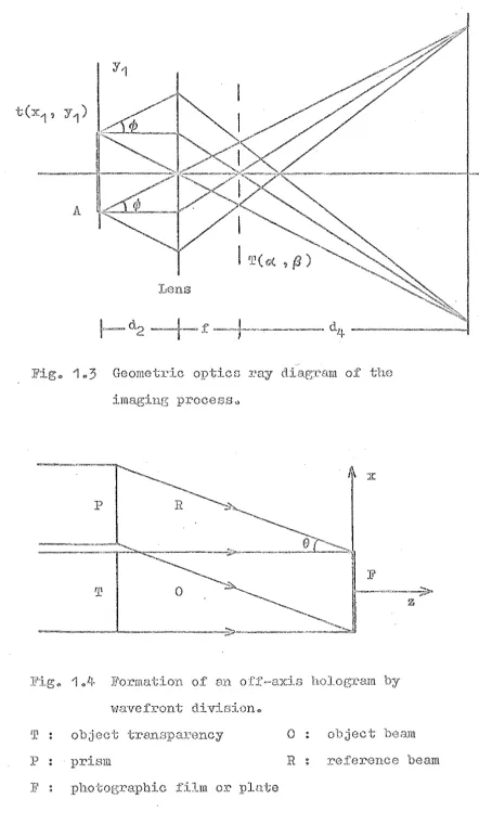
The Fourier transforming and imaging properties of a lens are conveniently illustrated by the geometric-optics diagram of Fig. 1.3 (Cowley 1975). As above, a plane wave is incident on the object and is imaged by a lens of focal length f . Waves scattered by a point A of the object are brought to a focus at A • in the image plane. From the geometry of the diagram the image is inverted and magnified by a factor d4/d2 • · Note that all waves scattered through an angle
¢
are brought to a focus at a single point in the back focal plane. This property is equivalent tointerference at a point at infinity when no lens is present, as shown in Fig. 1.1 when condition (1.3) applies. Hence the amplitude distribution in ·the back focal plane is that of the Fraunhofer diffraction pattern and is thus proportional to T(a,S). For ·this reason the back focal plane of a lens is often referred to as the "diffraction plane", especially in electron microscopy. Both terms are used interchangeably in this thesi~.
Although the geome·tric ray diagram of Fig. 1. 3 may appear to explain the Fourier transforming property of a lens i t merely illustrates the wave-optics descr~ption. The rays scattered by the object at angle
¢
have no existence in ·the domain of geometrical optics. Using wave-opticalproposed by Ernst Abbe in 1873 (see Born and Wolf 1970, p.420 for references, also Volkmann 1966). The imaging process consists of two successive Fourier transforms. First the diffracted radiation from the object in·terferes in the back focal plane to give the Fraunhofer diffraction pattern. Then the radiation from the back focal plane
forms an interfe_rence pattern in the image plane. When ·the image plane is effectively at infinity the amplitude .
distribution in t.he image is given by the Fourier ·transform of that in the back focal plane.
1.4 HOLOGRAPHIC IMAGING
1.4.1 Principles of Holography
Radia·tion emana·ting from an object contains
information about the object in ·the form of arnpli t.ude and phase variat.ions across the wavefron ts. If the waves are coherent the relative phases of the ~art= of a wavefront are cons·tant with time. A recording of surh a wavefront is
often required. However, conven·tional ;recor<'l.Lng media (e.g. photographic film) respond to the ave~age energy oj
the wave over a time interval corresponding to many wave periods. Hence the relative phases of the parts of the ·wavefront are not recorded. Only the spatial distribution
of the intensity (i.e. the square of the amplitude) of the wavefron·t can be reconstructed from such a recording.
Gabor (1948, 1949, 1951) realised the advantage of forming an interference pattern using the original wavefront and a reproducible reference wave. Only the intensity of the interference pattern can be recorded, but the original wavefront is reconstructed when the recorded "hologram" is illuminated with the reference wave. Other components are produced in addition to the desired reconstructed wavefront. However, the object and reference may be arranged to ensure that the desired image is separated in space from these unwan·ted components.
The radia·tion from the sources available to Gabor had only
a
limited degree of coherence. With such a source the only useful reference is the undiffracted component of the wave transmitted by an almost-transparent object.Interference of the undiffracted waves with the diffracted componen·ts produces a pa·ttern which when recorded forms an "in-line" hologram. However, the reconstruction from this type of hologram consists of the desired wavefront corrupted by other additive waves (Goodman (1968), tor example, gives a more detailed discussion). Although Gabor (1949, p.486) knew of other arrangements for the reoording of holograms their advantages could not be fully realis~d until the
interest in holography.
The simplest form of off-axis reference is shown in Fig.
1.4.
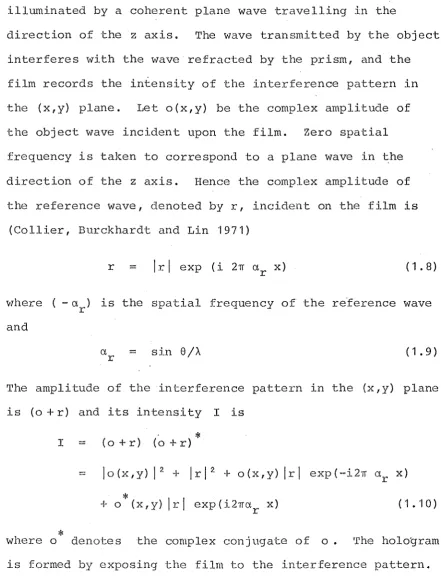
The object transparency and the prism areilluminated by a coherent plane wave travelling in the
direc·tion of the z axis. The wave transmitted by the object interferes with the wave refracted by ·the prism, and the film records the infensity of the interference pattern in the (x,y) plane. Let o(x,y) be the complex amplitude of the object wave incident upon the film. Zero spatial frequency is taken to correspond to a plane wave in the direction of the z axis. Hence the complex amplitude of the reference wave, denoted by r, incident on the film is
(Collier, Burckhardt and Lin
1971)
r
=
lrl exp (i 2~ ar x) ( 1 • 8)v7here ( -a ) is the spa·tial frequency of ·the re.ference wave
r
and
sin
e
/A.
( 1 • 9)The amplitude of the interference pattern in the (x,y) plane is (o
+
r) and its intensity I isI ( o
+
r) (o.
+
r)*
-- lo(x,y) 12
+
lrl 2+
o(x,y) lrl exp(-i27f ar x)*
+
o (x,y) lrl exp(i2~0''r x) (1. '10)*
[image:33.595.70.512.154.731.2]The exposure time and the subsequent processing may be selected (Butters 1971) to ensure that t is linearly
related to I, to a first approximation. Let
t
=
t - k I0 (1.11)
where t is the transmittance of unexposed film after
0
development, and k is a constant. Consider the effec·t of illuminating the hologram (transmi·ttance t) with ·the original
reference wave. The complex amplitude of the wave emanating
from the hologram is rt, and from eqns (1.8), (1.10) and
( 1. 1·1) it is composed of five terms:
rt
=
t lrl exp(i2rra x) o r+
lo(x,y) l2 lrl exp(i2'1Ta x) r+
lrl 3 exp(i2'1Ta x)+
lrl 2o(x,y) r+ lrl 2 o*(x,y) exp(i4•rarx) (1.12)
where the constant k is taken to be: -1 . Note that the fourth term is proportional to the original obj~ct wave. Following Leith and Upatnieks (1962), Collier, Burckhardt and Lin ( 19 71) .show that ·the reconsi:ructi0n of the original object wave is not contaminated by the other waves
represented in eqn (1.12) provided tba~
> 3 a max
where CJ, is the highes-t spatial frequency having
max
significant amplitude in ·the Fourier transform of ·the
(1.13)
object transparency. There is a large body of literature
on holography in which the basic result in eqn (1.12) is generalised to include the effects of partially coherent illumination, of film thickness, resolution,and
DeVelis and Reynolds (·1967), Goodman (1968), Stroke (1969), Collier, Burckhardt and Lin (1971), Menzel et al. (1973) and Cathey (1974).
1.4.2 Formation of Holograms
A "Fresnel" hologram is formed using the object and reference beam geometry shown in Fig. 1
.1+ •
This type of hologram results when the film is placed in ·the Fresnel diffraction region (near field) of the object (DeVelis and Reynolds 1967). Fresnel holograms require no lenses for their formation or reconstruction and they may be formed with radiation reflected from an opaque object (Leith and Upatnieks 1964).An "image plane" hologram is fo.rmed using the
arrangement shown in Fig. 1. 5 . ThE. lens forms an in-focus real image of the object which interferes with the reference wave to form the hologram (Bryngdahl and Lohmann 1968a,
Brandt 1969).
A lens may be employed to obta.in ~\vO waves which
represent the Fourier transforms of the object and reference source distributions. A record of the lnterference of these waves is known as a "Fourier transform" hologram (DeVelis and Reynolds 1967). When the reference is a poin·t source of radiation, as shown in Fig. 1.6, its Fourier transform is represented by a plane wave propagating at an angle to the film, cf. Fig. 1. 4 . In section 1. 9. 1 i t is
The reconstruction is obtained using a lens to form an image of the Fourier transform of the hologram.
Fourier transform holograms may be formed using an extended reference source instead of the point source shown
in Fig. 1.6 Spatial modulation of the reference wave from an extended source leads to the formation of a hologram
which can be used as a spatial filter for image processing (see Chapter 2) or for optical character recognition and similar applications (Vander Lugt ·]96 L}; Vander Lugt, . Ro·tz
and Klooster 1965). "Lens-less" Fourier transform holograms are formed when the geometry of Fig. 1.6 is used, but
without the lens. The source distribution of an acoustic or radio antenna may be det~rmined from a lens-less Fourier transform hologram formed in the far field of its radiatiori pattern (Bates 1971; Napier and Bates 1971, 1973).
Radiation from a known source distribu·tion is used as the reference wave. Other applications of acousti~ and radio frequency holography are described by Mueller (1971) and Le i t h ('1 9 7 1 ) •
Optical holography is now applied to a wide variety of problems in science, engineering and technology - see,
for example, Barrekette et al. (1971). Many applications are described in the books cited at the end of section 1.4.1
and in the reviews of Goodman (1971) and Gabor (1972).
When coherent light propagates through a randomly fluctuating medium, or reflects off a rough surface, i t forms an image which has a random distribution of intensity. Such images are known by ·the descriptive term "speckle"
systems when light is reflected off dust particles in the air and on lenses and mirrors, contributing a noise-like background to the desired image.
In contrast with their often undesirable aspects, speckle patterns ftnd a wide variety of applications
(Dainty 1975) - f o r an interesting example see Briers (1975). In optical astronomy, an unresolvable star may be used as a reference in the formation of a "speckle hologram" (Bates, Gough and Napier 1973). Images of multiple star systems may be reconstructed (Gough and Bates 19?4) after averaging a large number of such speckle patterns (Labeyrie 1970).
Holograms may be generated and reconstructed by a digital computer using simulated rather than physical wavefronts (Huang 1971). Computer reconstruction of
holograms is often the simplest approach in acoustical and microwave holography- see, however·1 Wu and Farha·t (1975). Gough and Ba·tes ( 1972) show how comp·.:tter genera·ted holograms may be used for image reconstruction from projections (see Part 2 of this thesis) .
1 . 5 IMAGE FORMA'l'ION IN THE ELECTRON Ivil:CROSCOPE
1.5.1 Phase Contrast Imaging
Figure 1.7 shows the components of the transmission electron microscope (Hawkes 1972). Electrons of high energy
Because of ·the wave-like nature of the electron beam,
image f6rmation in the electron microscope may be described using the Fourier theory approach to imaging introduced in section 1 • 3 •
The lenses used in electron microscopy employ specially shaped magnetic fields to focus the electron beam. Although considerable effor-t has been expended on their development (Ruska 1966) the aberrations of these lenses remain much more significant than the aberrations of light-optical lenses. Despite th~ use of modern
computer-aided design techniques (Hawkes 1973) the
resolution. of the electron microscope is limited by the spherical aberration (Septier '1966) of its objective lens. Frank (1974) discusses the theoretical limits of resolution imposed by lens aberrations.
The ·thin specimens examined in biological and high resolution electron microscopy absorb a negligible number of the electrons incident upon them (Erickson and Klug 1971). The thin specimen modulates only the phdSe of the
transmitted elec·tron wave. If the inc·;dent wave is of unit amplitude, the object wave a (x y ) transmitted by the
o o' o
specimen is
=
exp [ i t (x ,y ) ]0 0 (1.14)
where t(x ,y ) is a real variable representing the phase
0 0
shift of the transmitted wave. If t(x ,y ) is appreciably
0 0
less ·than unity, t.hen the "weak phase approximation 11
(Erickson 1973, Misell 1976) is -valid, i.e.
r:! 1
+
i t (x , y )where the higher ·terms in the expansion are insignificant. The unscattered wave and the scat·tered wn.ve ·transmitted by the specimen are represented by the respective terms on the
right~hand side of eqn (1.15). A specimen for which
eqn ( 1. 'I 5) is valid is known as a 11
weak phase object". For an ideal objective lens, the complex wave amplitude A(a,B) in its back focal plane is given by the Fourier transform of a
0 (x0 ,y0) . Let (p,¢) be polar
coordinates in the back focal plane corresponding to the Cartesian coordinates (a,B). The spherical aberration and defocusing of a non-ideal lens are equivalent to a
frequency-dependent phase shift X(P) which modifies the waves in the back focal plane (Erickson 197 3) • 'l'he amount of the phase shift, ih radians, is (Scherzer 1949)
X(P)
=
T {-
2~cs
4·
p4+
t,.f2 }
p2 (1.16)where C is the coefficient of spherical aberration and
s
f:,.f is the deviation from focus. The modified wave in the back focal plane is
A(p,¢) exp[iX(P)]
=
[o(p) +i T(p,¢)] exp[i X(P)]using eqn (1.15), where T(p,¢)
=
T(a,a) is the Fourier transform of t(x ,y )·.0 0
T(- a, -·B)
Since t(x ,y ) is real
o ·o
*
=
'r
(a,S)(1.17)
(1.18)
The complex amplitude a
1 (x1,y1) of the wave in the image plane is found from the inverse Fourier transform of eqn (1.17). Hence
with
(1.20)
where the integration is over the domain OA of the objective lens aperture (referred to the
a,B
plane) and constant factors relating to the image magnification are omitted.The recorded image (micrograph) depends on the intensity of the electron wave in the image plane. The exposure and subsequent photographic processing may be controlled so that the optical density (-log10
(transmittance)) of the developed film is proportional to the electron density (Valentine 1965, 1966). Note that the responses of film to electrons and to light are quite
different - for details see the references cited above.
The intensity of the electron wave in the image plane is, from eqn ( 1 . 19) ,
*
a
1(x1,y1) a1(x1,y1)
( 1 • 2 •j )
A comparison of equations ( 1 . 1 0) and ( 1. 21/ ;::;hows tha·t for weakly scattering specimens the electron microscope image is a form of "in-line" hologram. E'urther correspondences
between electron microscopy and holography are explored by Hans zen (1 9 71) , Lohmann ('19 7LI) and Mi sell (unpublished) •
For a weakly scattering specimen the term jo(x
1,y1)j
2
in·tensity in eqn ("1.21), and using eqns (1.18) and (1.20), the image contrast is found to be
a 1 ( x 1 , y 1 ) a
~
( x1 , y 1 ) - 1
=
I
J
OA [ - 2 T ( a ,S )
1.
sin{x((a2 +S2~ 2)}]exp[-i2;r(x
1
a+y1
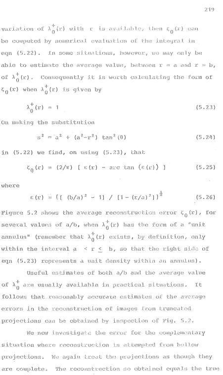
S)] dadS (1.22)Erickson (1973) obtains a more detailed result which includes the effect of the atomic scattering factor.
The Fourier inverse of eqn (1.22) shows that the Fourier transform of the in·tensi·ty con·tras·t in the recorded micrograph is proportional to T(p,~)sin{x(p)}, for all
spatial frequencies p transmitted by the objective
aperture. Hence an idealised electron microscope having no imperfections other than spherical aberra·tion and defocusing represents a linear, spac~-invariant imaging
system for weak phase objects. Now, T(p,~) is the transform I
of t(x , y ) , hence the factor sin{x(p)} may be interpreted
0 0
as ·the "transfer function 11
of the microscope (Lenz 197 'I) when a weak phase object is examined ns:i.ng eqn ( 1 .. 16)
~,vith a known value of Cs, the transfer function may be plotted for various values of defocus Af (Ha~szen 1970, Erickson and Klug 1971). Krivanek (197~) shows how ~f and Cs may be obtained from a test micrograph. Note that a micrograph would be featureless (zero contrast) for a weak phase object in ·the absence of spherical aberration and defocusing since X(P) is then zero. When x(p) is non-zero a "phase contrast" image is obtained. For biological
specimens, best results are obtained using ~f
=
-90 nm resulting in the transfer function shown in Fig. 1.8A band of spatial frequencies is imaged without significant distortion but some higher spatial frequencies are imaged with reversed contrast. The contrast reversals may be
eliminated by decreasing the size of the objective aperture, with a consequent loss of resolution.
1.5.2 Image Improvement
The ·transfer. function of the electron microscope could be improved by the introduction of selective phase shifts to the waves in the back focal plane of the objective lens. Annular "zone plates" to achieve this have been
widely investigated - see Hawkes (1973, p.6), Hanszen
(1973) and Stroke et aZ. (1971-~) and their references. Zone plates are capable of irnproving the performance of the microscope but their use inevitably introduces a new and pot.en·tially overwhelming source of aberration into the
electron optical sys·tem. A full discussion of the practical techniques is given by Willasch ( 1975) t.ogether ;,'lith
experimental results. Muller (1976) gives a detailed description of the manufacture of zone plates.
micrograph.
The micrograph of a weak phase object is particularly amenable to image processing. Unfortunately the weak phase approximation is inapplicable for many specimens of interest in electron microscopy, particularly metallurgical and
heavily stained biological specimens (Misell 1976). Further complications arise when the specimen modulates the
amplitude as well as the phase of the electron beam, which is likely for thick specimens (Cowley 1975). Similarly, realistic descriptions of image formation in the electron
microscop~ (e.g. Hanszen 1971) must take into account the
mechanism of "amplitude contrast" (Erickson 1973) and many characteristics of the microscope imaging system which are not discussed here. Hence in practice the transform of the micrograph is unlikely to be simply related to T(p,~) and
subsequent image processing is not straightforward. Given a detailed description of the microscope's
imaging characteristics, effective image processing requires a knowledge of the complex amplitude of the wave at the
microscope image plane. This wavefro11t may be reconstruc·ted from a hologram formed in the image plane of the microsciope. The following sections of this chapter discuss image
1 • 6 HOLOGRAPHY AND 'I'HE ELECTRON MICROSCOPE
The electron wave transmitted by a specimen contains information about its structure encoded in the form of
amplitude and phase variations across the wavefront. But unless the "weak phase" approximation holds, the phase of the wave in the image plane cannot be extracted from a single conventional micrograph.
Gabor (1948) conceived the principle of holography as a means of recording a micrograph so that the complex amplitude of the wave could be reconstructed, using light-optical processing to correct for the aberrations of the electron lens. Gabor performed a light-optical simulation of his method. Elec·tron microscope experiments were
initiated (Baine and Dyson 1950) and Rogers (1952)
significantly extended the light-optical implementations of holography. However the elec·tron microscope. experiments met with very little success (Baine and Mulvey 1952). At
·the time of these experiments ·the rPsolul:..i.on of ·the· electron microscope was limited more by instrument instabilities
(vibration, specimen stage drift and r:ontamin.:;:.t:ion, and
power supply fluctuations) than by the spherical aberrat.ion of the electron lens. The rela·tive weakness of the electron source compounded these problems, since very long exposure times were required.
Fraunhofer in-line holograms (see Collier e·t aZ. 197 'I 1
DeVelis and Reynolds 1967). Many of the practical
limitations of the electron microscopes used for the early holographic experiments have been overcome in modern
ins·truments. In-line Fraunhofer holograms have been formed in the electron microscope and successfully reconstructed using coherent light by Tonomura et al. (1968). Other results obtained by this research group are discussed by Hanszen (1973) 1 who also presents light-optical simulations
and further reconstructions from electron holograms.
However it seems unlikely that Fraunhofer in-line holography can be used to extend the resolution of the electron
microscope (Hanszen 1973) - see also thework of Munch (1975)
and Asakura et aZ. ('1977).
Off-axis holography in the electron microscope became possible when Mollc~ns·tedt and Duker (1956) developed the electrostatic biprism beam-splitter, which is the electron-optical equivalent of the Fresnel biprism used for light. The electrostatic biprism consists of a very thin
conducting fibre which is placed in the path of the electron beam. Typically a 1-2 11m gold-plat.ed quartz fibre is used
(Munch 1975) and a positive potential is applied to i t .. The electron wavefronts are divided and distorted in such a way that an interference pattern is produced below the fibre as if the electrons were coming from two coherent sources either side of the original electron beam. Mollenstedt and Duker (1956) present electron interference patterns produced by such a biprism. The relevant theory is given by Gabor
. Menter ( '1956) used electron interference in the microscope to assist the study of crystal lattices. Faget and Pert (1957) and Buhl (1959) built special "interference" electron microscopes incorporating the biprism beam splitter, which was positioned following the objective lens. With no specimen in the microscope, the two virtual sources produced by ·the beam split·ter form an interference pat·tern in ·the image plane. A specimen in such a microscope is effectively in one arm of an interferometer (Saxon 1972a). A hologram is formed in the image plane, where the "object wave''
consists of the wave scattered by the specimen and the undiffracted background wave be·tween ·the specimen and the biprism (Munch 1975). MBllenstedt and Wahl (1968) form a hologram of this type in the electron microscope and from i t reconstruct an image of the spec~men ~sing laser light. They illumina·te the specimen using a line focused electron beam v7hich is coherent with respect 1-.o only one spatial dimension. Hence the hologram is e~~sentially
one-dimensional, and linear fringes are cJsR~Jy visible in the published photograph of their holograr::. More conventional holograms are formed by Tomita, Matsuda and Komoda (1970, 1972) using a circularly symmetric coherent electron source and electrostatic biprism.
experimental details. The holograms are reconstructed
optically using a laser. He also demonstrates (Saxon 1972b) optical compensation of elec·tron lens aberrations. However
f)
the best resolu·tion ohtained is only about 500 A, i.e. two orders of magnitude inferior to the performance of the
conventional microscope. This work is ext.ended by Munch (1975) who achieves resolutions in the optically
If)
reconstructed i~age of 50 A for off-axis Fresnel electron I)
holograms and 10 A for in-line Fraunhofer holograms. He finds that the performance of both types of hologram is limited by a lack of sufficient contrast. In the Fresnel hologram, the object wave consists of the wave scattered by the specimen added ·to the undiffracted beam, hence the image of the specimen is reconstructed with only a low contrast. The in-line Fraunhofer hologram of a small par-ticle has insufficient contrast to enable a useful image to be reconstructed from i t (Munch 1975). Such a hologram is indistinguishable from a well-focused micrograph ..
Defocusing of the microscope magnific3tion system improves the image contrast (by th~ phase-cont~cs~ mechanism discussed in section 1.5.1) but the contrast of the holographic
interference fringes is reduced further. The fringes have insufficient contrast to be recorded by the film, hence no useful reconstruction of the small particles can be obtained from the hologram.
plane wave of light as an auxiliary reference. Weing~rtner, Mirande and Menzel (1969) argue that image plane holography using a bipr lsm is the most suitable met.hod for forming holograms in the electron microscope. They present a detailed analysis (Weingartner, Mirande and Menzel 1970) of the effects of partial coherence of the electron beam. However, their general conclusions are no·t shared by
Hanszen (1973) who states that in-line holography should be used, particularly for weakly scattering objects. He
argues that wavefront division to derive an off-axis
reference beam always requires asymmetrical electron optical elements. Such an element (e.g. a biprism) disturbs the rotational symmetry of the imaging system and the electron lens aberrations are severe for the waves which do not propagate close to the optical axis of the system.
1 • 7 NEW PRO:POSALS FOR gLECTRON HOLOGRi\PHY
1. 7.1 Introduction to Cry~sto-·r~lOlograp~
In light optical holography, off-axis reference waves are used where possible in preference to the in-line
configuration. When ·the reference beam is sufficiently off-se·t (condition ( 1 ~ 13)) the recons·truction of the object wavefront is not contaminated by the other waves
reconstruc·ted from t.he hologram.
The formation of a Fourier transform hologram
(section 1.4.2, Fig. 1.6) in the electron microscope retains the advantages of off-set holography but avoids the
objective lens is the only modification to the electron optics which is required for the formation of this type of hologram. There is, however, i:.he requirement of a point source in the back focal plane. This source must produce a reference wave of reasonable strength so that the
interference fringes are of sufficient contrast to be
recorded by the film in the image plane of the microscope. Bates and Lewitt (1975) suggest that one of.the higher order Bragg reflections in the diffraction pattern of a crystal would be sui table. The name "crysto~·holography" seems
appropriate to describe the formation of a Fourier transform hologram using a reference wave derived by diffraction from a crystal. Sec·tion 1. 9 gives a detailed descrip'cion of
crysto-holography, essentially unchanged from tha·t presented by Bates and Lewitt (1975).
Menter (1956) describes intetference experiments with crystalline specimens in the electron microscope. When only two of the crystal diffraction orders are transmi t:ted by an aperture in the back focal plane, an ~nterference pattern is formed in the image plane. Interfere~cH pattsrns of this L.ype are widely used as a test of the electron microscope
(Sieber and Tonar 1975, Munch 1975).
Section 1.9 uses the principle of off-set holography to extend the interference technique pioneered by Menter
applications, for instance) that i t remains undamaged after prolonged exposure to the electron beam. Crysto-holography enables reconstruction of the phase, as well as the
intensity, of the diffraction pattern of faults or dislocations in a crystal, which are of fundamental
importance in material science - see, for example, Valdre (1971).
The methqd of crysto-holography may be used to
reconstruct the complex amplitude of the diffraction pat-t:ern of an aperiodic ( L e. 11
amorphous 11
) specimen deposited on to
a crystalline substrate. In this case only a single exposure to the electron beam is required. 'I'he substrate should be as perfect a crystal as possible, but the demands that this
requirement places on specimen preparation techniques may not be trivial. In a related context i t is interesting to note that Croce and N~vot (1975) study the X-ray diffraction from a composite specimen consisting of an amor~hous
substrate on which a thin layer of crystal is deposited. If i t proves technically feasible to ?repare specimens of this type for the electron microscope, t~en crysto-holography may be a convenient method of obtaining the phases of