ELECTROMAGNETIC SCATTERING 0
A thesis presented for the degree of Doctor of Philosophy
in Electrical Engineering, in the University of Canterbury,
Christchurch, New Zealand,
by
I am greatly indebted to my supervisor Mro RoHoTo Bates whose insight, guidance, and encouragement have contributed so much to this thesiso
An expression for the field scattered by a perfectly conducting wedge with a deformed apex is formulated as a finite matrix equation to illustrate the application of the current density replacement technique. This technique enables the scattering from any size of body to be determined to a given accuracy after the inversion of one finite matrix, provided that the shape of the body can be derived by inward-ly deforming a finite part of a body from which the scattering is known explicitly~ The size of only the deformed part of the body is limited by available computational facilitieso
The field scattered from truncated and rounded wedges is calculatedo These results not only enable the effect of
edge deformation to be studied¥ but are also used to evaluate the accuracy of the geometrical theory of diffraction and physical optics estimates of the diffracted fieldo
Expressions for the field scattered by a perfectly con~
ducting wedge in the presence of transversely polarized line sources are found. These results are used with an iterative current density replacement technique to formulate expressions for the field scattered by a truncated wedgeq and thus derive
a secondary edge diffraction coefficient for use with the geometrical theory of diffractionq This coefficient is
applicable to perfectly conducting bodies with small or
large separation between edges" The increased accuracy obtain-able with this coefficient, and a modification to the physical optics representation of the current density on a body
H E B D J q A
u
K(x) 110 s o w c kJ (z)
\!
H(2) (z)
\!
magnetic field intensity electric field intensity magnetic flux density
electric flux density electric current density electric charge density magnetic vector potential Ef H, or A
surface current density at x ~ permeabili ty
permeability of free space permittivity
permittivity of free space
angular frequency; variable of integration
-~ velocity of electromagnetic propagation c
=
(11s)wavelength
wavenumber k
=
w/c=
2n/ABessel function of the first kind of order \! and argument z
Hankel function of the second kind of order \! and argument z
c
(z) ,C (z) Any cylindrical Bessel function of order \! and \! \!argument z
X
r
n
-+
F
\j X \j 0
(p,</l,z)
(s,8,Z) (r,8,z)
(s,o,z)
time derivative of X, X
=rr
unit vector
outward unit normal vector to a surface or contour the vector of magnitude F
the vector curl operator
the vector divergence operator the vector gradient operator
cylindrical polar co-ordinate systems
-+
E
=
zE, A +=
zA electrically polarized-+
H
=
zH magnetically polarizedGeometrical optics
Geometrical Theory of Diffraction Physical optics
Polarization Current Replacement SoCoR. Surface Current Replacement
Iterative Surface Current Replacement Modified Physical Optics
PREFACE CHAPTER 1
lol(a) Explicit Solutions
(b) Scattering by a Perfectly Conducting Wedge lo2(a) Integral Equation Representation
(b) Modal Expansions
lo3(a) Ray-tracing Techniques
(b) Edge Diffraction Using the GoToDo lo4(a) Physical Optics
CHAPTER 2
201(a) Polarization Current Replacement (b) Surface Current Replacement
202(a) The Deformed Wedgeo Electric Polarization (b) The Deformed Wedgeo Magnetic Polarization (c) Comments on the Results of Section 202 CHAPTER 3
301(a) Truncated Wedgeo Electric Polarization
1 6 6 7 13 16 25 29 33 37 38 41 44 52 62 66 66 (b) Surface Current Continuityo Electric Polariz- 74
ation
(c) Truncated Wedgeo Magnetic Polarization (d) Surface Current Continuityo Magnetic
Polarization
79
302 (a) Rounded Wedgeo Electric Polarization
(b) Rounded viJedge 0 Magnetic Polarization
30 3 (a) Numerical Considerations
(b) Programming ( c) Results CHAPTER 4
401 (a) Introduction
402 ( a) GoToDo Diffracted Fieldo Truncated Wedge 0 Electric Polarization
(b) GoToDo Diffracted Fieldo Truncated Wedgeo
Magnetic Polarization
( c) GoToDo Diffracted Fieldo Rounded Wedge
403 (a) Physical optics Fieldo Electric Polarization (b) P.Oo Fieldo Truncated Wedgeo Electric
Polarization
(c) PoOo Field Rounded Wedgeo Electric Polarization 88 92 96 100 103 113 113 115 118 122 125 128 130 404(a) Physical Optics Fieldo Magnetic Polarization 132
(b) PoOo Fieldo Truncated Wedgeo Magnetic
Polarization
(c) PoO o Fieldo Rounded Wedgeo Magnetic Polarization
405(a) Numerical Considerations
(b) Results
134
5o l(al Introduction
502(a} Transversely Polarized Electric Line Source
164
164 (b) Transversely Polarized Magnetic Line Source 173
CHAPTER 6
6 a 1 (a) The L, Ro Technique
60 2(a) Truncated Wedgeo Electric Polarization (b) Truncated Wedgeo Magnetic Polarization CHAPTER 7
7ol(a) Comparison of GaToDo and loRa Technique 702(a) Truncated Wedgee Electric Polarization
(b) Truncated Wedgeo Magnetic Polarization 703(a) The laRa Diffraction Coefficient Applied
to a Truncated Wedge
(b) The loRe Diffraction Coefficient Applied to a Conducting Strip
(c) Numerical Considerations (d) Results
704(a) Modified Physical Optics (b) Some Definitions
(c) MoPoOo Applied to a Truncated Wedge
(d) Discussion and Results
This thesis is concerned with the computation of electromagnetic scattering, particularly from perfectly
conducting bodieso
It is evident from recent volumes of the IEEE Trans-actions on Antennas and Propagation that considerable
attention is being devoted to the application of ray-optical techniques to electromagnetic scattering problems. Diffract-ion by horns and obstacles in waveguides has received
particular attention 0
In order to be able to evaluate the accuracy of ray-optical and other approximate methods of determining
electromagnetic scattering, i t is desirable to have available solutions to other than simple scattering problems. This thesis presents techniques for determining such solutions 0 These techniques are essentially new and are of interest in their own righto
The field scattered from a perfectly conducting wedge with a deformed apex is calculated by using a current
density replacement technique. The results not only enable the effect of edge deformation to be studied, but are also used to evaluate the accuracy of the geometrical theory
of diffraction and physical optics estimates of the diffracted fieldo
Expressions are found for the field scattered by a
polarized line source 0 These results are used with an
iterative current density replacement technique to formulate expressions for the field scattered by a perfectly conducting truncated wedge, and thus derive secondary edge diffraction coefficients for use with the geometrical tbeory of diffract-iono These coefficients are equally applicable to perfectly conducting bodies with small or large separation between edges. The accuracy of these coefficients, and a suggested improvement to the physical optics representation of the current density on a body with edges, are evaluated.
Chapter I is introductory. New results are presented in Chapters 2 - 7.
Chapter I contains a brief survey of several well
known methods of determining electromagnetic scattering which are relevant to this thesiso Mention is made of papers which show the usefulness and limitations of these methods.
or even infinite bodies to be calculated o
The current replacement technique is used to formulate expressions which describe the field scattered by a
perfectly conducting wedge with a deformed apex, and in Chapter 3 this formulation is specialized to the truncated and rounded wedgeso Results are presented which illustrate the convergence of the solutions as the matrix order is
increased o It is found that the convergence is accelerated i f explicit use is made of the analytic properties of
the surface current densityo
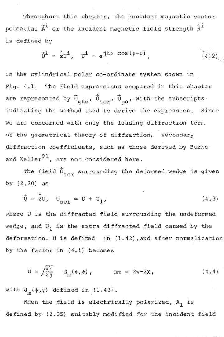
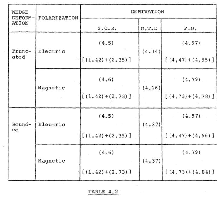
The results of Chapter 3 are used in Chapter 4 to study the accuracy of the physical optics and geometrical theory of diffraction estimates of the field scattered by a
perfectly conducting wedge with a deformed apex 0 Of particul-ar interest is the accuracy of the geometrical theory of
diffraction applied to the truncated wedge when the distance between the two edges is less than one wavelength 0 It is
found that when the incident field is magnetically polarized parallel to the wedge axis, the inclusion of the higher
order diffracted fields may lead to inaccuracieso However in other casesp such as the prediction of the end-on
electrically polarized backscattered field, the geometrical theory of diffraction yields accurate estimates even when the separation of the edges is as small as 0005 wavelengthso
Chapter 50
The results of Chapter 5 are used in Chapter 6, where the field surrounding a perfectly conducting
truncated wedge is formulated by successive application of the current replacement technique to two separate perfectly conducting wedgese The expressioffifrom the first two such applications are obtained.
It is shown in Chapter 7 that these expressions not only give rise to terms describing the primary field of the geometrical theory of diffractiong but also describe a secondary diffracted fieldc The resulting secondary diffraction coefficient is identical to that of the
geometrical theory of diffraction when the edge separation is large, but is also valid when the distance between the edges is smallo Unlike the geometrical theory of
diffraction secondary diffraction coefficientv this diffraction coefficient is not zero when the field is electrically polarized parallel to the edges of the bodyo Results are presented which show the increased accuracy obtained by using this coefficient to approximate the field scattered from the truncated wedge and perfectly conducting stripe The improvement in the representation is
An improvement to the physical optics representation of the surface current density on a perfectly conducting body with edges is suggested in Chapter 7. It is shown
that this suggestion is equivalent to representing the diffracted field by the primary diffracted field of the geometrical theory of diffraction and two correction terms
for each edge of the bodyo Results are presented which show the increased acCuracy obtained by using the modified physical optics current densityo
Chapter 7 concludes with suggestions for further areas of research o
Some results in
Chapte~2
and 3 have been published;,2 as have the derivations in Chapter 50 3The computer programs required for this thesis were written in the Fortran IV language using the double
precision option, and were executed on an IBM 360/44
computer which has 64K bytes of core memory 0 All programs and subroutines were written by the author of this thesis, with the exception of the IBM subroutine MINV which,
CHAPTER 1
Four methods of determining the electromagnetic field surrounding a scattering body are discussed in this chaptero The first of these methods requires the derivation of an explicit solution to the scattering problem, and the
second involves the use of modal expansions in conjunction with an integral equation representation of the scattered
fieldo The use of ray tracing techniques including the geometrical theory of diffraction is the third method discussed, and the fourth is the physical optics
approximation 0
lol(a) EXPLICIT SOLUTIONS
A rigorous description of an electromagnetic
scattering phenomenon requires the solution of Maxwellas field equations
v
XE
=
-B
fv
XIi
=
J
+13,
(101)
v
0D
=
q,v
0B
=
0,formulated as a boundary value problem 0
Use of the classical separation of variables technique with the Helmholtz equation
v.2 U
+
k2U=
0is possible in only eleven separable co-ordinate
systems4 when the surface of the scatterer conforms to
a complete co-ordinate surface. Rigorous solutions can be obtained when the scattered field is described by equations of the Wiener-Hopf type5, but the total number of known explicit solutions of Maxwell's field equations formulated as boundary value problems remains extremely limi tedo
One such known solution describes the field scattered by an infinite perfectly conducting wedge. Because much of
this thesis is related to the problem of scattering by a wedge, several forms of the solution to this problem will be examined in some detailo
10 1 (b) SCATTERING BY A PERFECTLY CONDUCTING WEDGE
Consider the infinite perfectly conducting wedge of interior angle
S
and surface contour C defined in terms of the (Pf~'Z) cylindrical polar co-ordinate system in Figo 101 by ~= 0 and ~=
m~q where(10 3) The wedge is of infinite extent in both the positive and negative Z directionso When the incident field exhibits no variation in the Z direction i t is necessary to consider
the variation of field quantities i~only the P and ~
directions o The problem then becomes two-dimensional, and even though the fields are described in terms of electro-magnetic quantities, the expressions are equally applicable
The wedge is surrounded by a homogeneous, isotropic, time-invariant medium of permeability ~, and permittivity 'Eo The total field U surrounding the wedge must satisfy
the Helmholtz equation (101) at all source-free points, and either the Neumann boundary condition
3U
=
03n ' on
C,
(1. 4)when the field is magnetically polarized
(H
=
z'H) , " or the Dirichelet boundary conditionU
=
0, on C, (1.5)-7- (0.
when the field is electrically polarized (E
=
zE) 0 n is the direction normal to the boundary contour C, and k2=
W2~E
in (102) 0 The suppressed monochromatic time dependence is exp(jwt) 0 The Neumann boundary condition corresponds to the sound-hard boundary, and the Dirichelet boundary condition to the sound-soft boundary in acoustics.In 1896, Sommerfeld obtained expressions describing
7
the diffraction from a perfectly conducting half plane • Macdonald used the method of separation of variables to obtain both series and integral representations of the
8 9 field scattered by a perfectly conducting wedge ' •
-7-'
When the incident field Ul is the plane wave
-7-U
=
z·U, Ui=
e jkpcos(~-W) , (1. 6)given by
U(p ,</»
=
W (p , </> -lj!) ± W(p,</>+lj!), (10 7)where
W(p
,U
=
Vl(p,O + V2 (p,l;), (108)'~
Vl(p,l;)= ejkpcoS(~+2pTrm)
Is;
+ 2pTrm1<
Tr ,=
0,Is;
+ 2p'ITml > Tr,
(109)V2(PIs;) 1
fe
1~
ejkpcosa
da, (1010)
=
2Trm(-j [a+S;J) e m · 1
and p is any integer or zeroo The upper ( lower) sign in
(107) applies when the field is magnetically (electrically)
polarizedo
By performing a contour integration, Pauli obtained
V2 (p,S;) in the formlO
da
Ikp (l+cosS;)
Pauli showed that the higher order terms in (loll) are
,
identically zero when S
=
0 (the case of the half plane) , and can be neglected if kp (1 + cos~) is large. In this latter case, the asymptotic form of the expression in(1.11) is given by
kp(l+cosi;) »1, (1. 12)
where the first neglected term is of the order of p
The expressions for V2(Pf~) given in (1.11) and (1012) with
S=
0 are identical to those obtained by Sommerfeld.Oberhettingher found a different asymptotic
expansion of (1.11) involving only trigonometric functions in the higher order termsllo
Consider a line source situated at (p ,~) in Figo 601
o
such that the incident field vi is given by
Then a solution is required to
cS(p-p ) cS(~-~)
o
(1.14) Po
U(p,t)
=
-j\! 400
I
En J (kp) H(2)(kp ) {cos[n\!(t-1jJ)]n=O n\! n\! 0
± cos [n \! ( t+ 1jJ) ] } , (10 15) where \!
=
11m,
and En is the Neumann factor defined asEO
=
1; En=
2, nf
O. The expression in (1.15) may also 13be written as
(10 16) where
-1
rl(p,S)
=
8TI
coshv - cos(!) (1017)
and the upper sign in (1016), as in (1015), is to be taken with the boundary condition (1.4) for a magnetic line source; and the lower sign is to be taken with the boundary condition (105) for an electric line source 0 By deforming the contour of integration in (1017) into the t ' h t lines ' , , , 7 f , 7f ,7f 00 + J' ~
s ralg JOlnlng 00 -Jffi' -Jffi' Jffi' m '
and accounting for the included poles which occur only on the imaginary axis, Jones showed that
=
-4j H (2) {k[ p2+p2_2pp cos(~+21fpm) ]~} ,1~+21fpm
I
<1f,0 0 0
(1.19 )
=
0,I
~ + 21fpmI
> 1f,00
-J' S.ln , (' ]V+m""": . 1f) H.. 0 0 0 (2){k[ 2 . . P +p +p 2 2 P cos h( mv )J~} d v,
=
8TI
(1.20)
- - 00
and p can take any integer value or zeroo
At a large distance from the line source at (po,w), the incident cylindrical wave given in (1.13) appears as a plane wave, as evidenced by the asymptotic expansion of the Hankel function of the second kind14,
H (2)( v z
)~
I
! 2 j e - j (z- V21f) ~,
(1.21) After using the binomial theorem to expand the arguments of the Hankel functions in (1.13), (1.19), and (1.20) forPo » P, and multiplying the expressions in (1.13) i (1015),
(1019), and (1.20) by the normalization factor
'JTI"kP:
j k p4j/--:;f
e 0 , (1.22)i t follows that when the field incident upon the wedge
is the plane wave given in (1.6), the total field described in (1015) becomes
00
U(p,<P)
=
vI
En jnvJnv(kp)'{cos[nv(<p-w)] ± cos[nv(<p+w)]},n=O
and from (1.19) and (1.20),
I
~+27TpmI
< 7T,=
0,.I
~+27TpmI
> 7T,00
, (' +7T) -jkp cosh (mv)
1 Sln ]V
in:
.e .. dv.w2(P,~)
=
2TI
cos (jv+!.)
-
·cos(I)m m
(1. 25)
00
When kp is large, W2(Pf~) can be evaluated by the method of stationary phase15, which results in
7T -]'kp sin (-) e
m
W
2 (PnS) .
=
7T ~ ,Ij 27Tkp . m[ cos (m) -cos (ill) ]
kp » 1,
I
~I
(1. 26) Comparison of the expressions in (L 7) - (1.10), (1.12) v
with those given by (1.16) , (L18) , (1.24) - (1.26), shows that corresponding expressions are identical except for that in (1.25). This expression is mathematically more tractable than either (1.10) or (1.11).
1.2(a) INTEGRAL EQUATION REPRESENTATION
Although rigorous explicit expressions describing the scattered field have been determined for only a few bodies, i t is possible, by using an integral equation representation, to describe implicitly the field
equation is composed of two parts: a source distribution which describes the shape and composition of the scatterer, and the Greens function appropriate to those sources.
The body considered here is homogeneous and isotropic, has permeability ~s' permittivity ES' conductivity 0, and occupies a volume
v.
It is surrounded by a homogeneous isotropic medium of permeability ~ and permittivity E in-+
which exists a current source J. Maxwell's equations in (10 l) enable the field at any point to be described by
.
.
( ~ E - -2 E 1 ) -+ + ~ 0E -+ + ~J -+ + II II. E ( - + ) + II ~ X Hi -+
S S
C
where c is the velocity of electromagnetic propagation in
(10 28)
the surrounding medium. By defining the scattered field
US
asU
-+s -+ -+i
=
U - U , (10 29)where vi is the field incident from the source distribution
-+
- jw( ••
i
+
v. x
i~
G(kR) dv, (10 30)11 - 11 j1 E - E E
~S - ~r' s - r ' k is the wavenumber appropriate to the
surrounding m'edium, R. is the distance from tYre elemental volume dv to the point P, and G(kR)
=
e -'kR J /4~R 1S the , three-dimensional Greens function 0When the surface S of the scatterer is perfectly given by
+
conducting, the scattered field is
i'is(P)
=
(*lffs
k(s) G(kR)ds,where the surface current density K(s) on S is defined by
+ +
K(s)
=
n X H, (10 33)and n is the outward unit normal vector to S at So The vector operator {*} is { -. j j1 c ( k 2 2 + 1/ 1/ 0 ) / w } when U +
represents the electric f1eld 1ntens1ty E, and is ' , , + {I/ X} when + U represents the magnetic field intensity + Ho
(1. 34)
+ . + +
1
- E X Va -Jw(~aH + E X VE~ g(kR) ds, (1 • 35)
jJS(P)
~
{A}L
K(C) g(kR)dc, (1.36)where {A} is {-jw~} when
U
represents the electric field+ +
intensity E, and is {v X} when U represents the magnetic field intensity
H.
g(kR) is the two-dimensional Greens function obtained by integrating the three-dimensional Greens function along an infinite path in the z-direction:g (kR)
=
+
z2)~l
dz=
:-jH (2) (kR) • (1. 37)J
4 0The first terms in the kernel of the integrals in (1.30), (1.31), (1.34), and (1035) are often referred to as the "polarization current density".16 The remaining terms in these kernels can also be regarded as polarization current densities.
lo2(b) MODAL EXPANSIONS
density in the integrand of the integral equation is determined, the field at any point can be calculated. Techniques which represent the current density as a modal expansion and use numerical methods to evaluate
the modal coefficients are known as Moment Methodso17 The simplest method of modally expanding the current density is the method of subsections. This involves sub-dividing the volume or surface of the scattering body into N parts, and approximating the current density in the nth part by the unknown constant Kn. Alternatively, the
electric or magnetic field intensity may be approximated by an unknown constant in the nth part. The integral over the volume or surface is approximated by a summation over the N subsections 0 N simultaneous equations are derived
by equating the two representations of the field or
current density in each of the N subsections. These simul-taneous equations can be derived for a perfectly conducting body by ensuring that the boundary conditions are satisfied at a point in each subsection. Care must be taken in
dealing with the singularity which occurs in the Greens function when the effect of the sources on themselves is considered.
The position at which the boundary condition is enforced in each subsection of a perfectly conducting
of subsectionso18 Hashimoto and Fujisawa conclude
that the best positi6n is the midpoint of each subsectiono The application of the method of subsections to a perfectlY,conducting body having a surface with edges
. . 1 . d t ' 19
or corners requlres specla conSl era lono' When the field is ele6trically pol~rized parallel to an edge,
the surface current density is integrably infinite at the edge032 Kay and Nihen33 studied the, effect of decreasing the subsectional size near an, edge, and also the effect of considering the edge to have a small but finite radius of curvatureo They found· that the forward scattered field is insensitive to the subsectional arrangement near the edge, except when the radius of curvature .of the curve
approximating the edge becomes too large.
Andreason19 uses the method of subsections in conjunct-ion with (1036) to formulate the scattering from
two-dimensional metallic cylinders as a matrix equationo He ensures that the boundary condition in (1.4) or (1 05) is, satisfied at the midpoint of each of the N subsections. The problem of the singularity of the Greens function p which
Results are presented for various single and multiple cylindrical bodieso
Earlier g Mei and van Bladel had used the method of
subsections to obtain the surface current density on perfectly conducting, rectangular cylinders, and hence
the scattered field: 0 Many of their results have since b een experlmenta ' 1 1 ' y ver1 1e f' d 21 0 However, the resonance
phenomenon which appears in one of their results is
. 22
1ncorrecto Such resonances may arise during the course of a numerical solution if resonant field modes can exist in the interior of the scattering bodY023,24,25
However, these resonances can not exist if use is made of the extended boundary condition25,26 in the formulation of the scattering algorithmo
The extended boundary condition requires not only the satisfaction of the boundary conditions in (104) or (105) on the surface of a perfectly conducting closed body; but also that the total field be zero in a region interior
4 25 29 to the bodyo Analytic continuation arguments ,. f
ensure that if such a condition is met, the field is zero everywhere inside the bodyo Thus i t is impossible for
resonant field modes to exist in the interior of the scatterer and con tribute to the surface current density 0 Al though
the extended boundary conditions to be certain of obtaining accurate values for the surface current density on the bodyo A "Null field method" is a method which employs. the·
extended boundarycondi tion in the formulation of a scattering problem.
"Point-matching methods" rely on satisfying the
boundary conditions at points on the surface of a scattering body in order to determine the field modal coefficientso27
28
Fuller and Audeh use the point-matching method to determine the cutoff frequencies of a nonsymmetric waveguide. They observe that the point-matching method becomes less accurate as the boundary contour of the waveguide becomes more
complicatedo 29
Bates has recently critically appraised the point-matching method and calculated the cutoff frequencies of various modes in several waveguides. He shows that
identical expressions are obtained for the cutoff frequencies of a waveguide whether the boundary conditions or the
extended boundary conditions are invoked.
Richmond16 uses the method of subsections to calculate the field scattered by. an infinite dielectric cylinder when the incident field is electrically polarizedo A matrix equation is derived by substituting V].l
=
(J=
0 into theexpression in (10 34) and representing the total electric
f ' ld . le lntenslty ln t e n " h th su sectlon b ' b y th e cons ant t
+
t ' (+ +Ei) h ' d ' h th b t' equa lng . E n - at t e ml pOlnt of t e n su sec lon to the expression on the right-hand side of (1034) 0 This latter expression is approximated by a summation over the N subsections o The singularity in the Greens
function is overcome by integrating over a circular region of the same cross-sectional area as the nth subsectiono This integration is easier to perform than that over a rectangular subsection, and Richmond maintains that i t introduces little error~ Results are presented for dielectric shellsv and homogeneous and inhomogeneous dielectric sheetso
When the field incident upon a homogeneous dielectric scatterer is magneticallY polarized, and Va
=
a=
0, ~r=
Ii the integrand in (1035) retains a term inE
X VEo Thebest method of dealing with this polarization current density term, which exists only on the surface of the dielectric, is not immediately apparent
Bates30 uses the method of subsections to determine
the scattering from a wedge covered with finite distributions of dielectricq when the field is magnetically polarizedo
+
He neglects the E X VE polarization current density term
in (1035) and thereby implicitly assumes that for the narrow
dielectric wedges studied, this term has the same
dielectric cylinder by expressing the magne.tically
polarized field in terms of the electric field intensityo The scattered field is evaluated by using the method
of subsections and the expression in (1034). Results
are presented for cylindrical shells and dielectric slabs o Because the method of subsections approximates the field or current density by a constant value in each
subsection, the modal expansion of the method is discontin-uous across each·suhsection boundary 0 However, by summing N continuous modal functions each weighted by an
unknown coefficient, the field or current density can be represented in a continuous manner over the region of interesto
34 . , h d 1 .
Bates uses a Fourler serles as t e mo a expanslon of the surface current density on the perimeter of a
perfectly conducting cylindero The null field method is used to extract the Fourier. coefficients of the incident and scattered fieldso It is shown that fewer surface current density modes· are required to, calculate the
36
Mullin et al express the scattered field exterior to an infinite perfectly conducting cylinder of arbitrary cross-section as a sum of outward travelling waves o By enforcing the boundary condition in (104) or (105) at points on the boundary~ the unknown coefficients of the scattered field modes are obtained o The results fail "for cylinders which are large perturbations from the circular"o36 By continuing the outward travelling representation of the scattered field back to the.surface of the cylindrical
II ' h ' k d h I ' h h h ' 37 scattererf Mu ln as lnvo e t e Ray elg ypot eS1S
38-41 which I during the course of a recent controversy has
been shown by Millar38 to be incorrect in generalf and in
particular incorrect for elliptical scatterers of appreciable eccentricityo This explains the failure of some of Mullin!s resul ts 0
The scattering for nose~on incidence from perfectly conducting cones with blunted tips is evaluated by
Weiner and Borison42 by representing the total field in a general eigenfunction expansiono After satisfying the boundary conditions and ensuring that the incident part of
the total field is equal to the incident field? the eigen-function coefficients are obtainedo
43
three-dimensional dielectric bodieso The fields inside and outside the body are written as modal expansions with unknown mode coefficientso By using the boundary
conditions44 to relate the expansions across the dielectric boundary a matrix is derivedff which after inversion
enables the modal coefficients to be obtainedo
The determination of scattering by using a modal representation of the field or current density requires the inversion of a matrix in order to find the modal coefficients 0 The order of the matrix is dependent upon th e n.um er b 0 f mo es use d d ' In t e representatlono h · . 17,45
When using the method of subsections~ the extent of each subsection must be less than half the wavelength.
of the highest spatial harmonic of interest in the field or current densitYo19 Andreason19 suggests between four
and ten subsections per wavelength of the incident field is adequate in the case of metallic scatterers, and
' h d16
R1C mon suggests 5/~r subsections per. wavelength for dielectric scattererso It follows from these considerations that the size of scatterer which can be dealt with by
moment methods is limited by the capacity of available
t t ' 1 f 'I' t·' 45
compu a lona aCl 1 leSo The limit on the
limit to be increased significantly. 1.3(a) RAY-TRACING TECHNIQU~
Both the integral equation repres~ntation of the scattered field discussed in section 1.2(a), and the rigorous explicit solutions mentioned in section l.l(a), describe exactly the total field surrounding a scattering body. The ray tracing techniques discussed in this section give an estimate of the field surrounding the scatterero The accuracy of this estimate depends upon the nature and shape of the scatterer as well as the sophistication of the ray-tracing technique employed.
Ray-tracing techniques are based on the assumpt.ion
that the field propagating from one point to another travels along ray paths joining the two points. Fennat Us principle states that the rays between two points "are those curves along which the optical path length is stationary with
t t ' f' ' t ' 1 ' t ' l'n path".46 Th respec 0 ln lnl eSlma varla lons e
intensity of the field predicted by ray theory is obtained by applying the principle of conservation of energy to a tube of rays.
The simplest ray-tracing theory is Geometrical optics
(G"o.). The field U predicted by geometrical optics
go
in the vicinity of a scattering body is defined as
where Ui is the incident field? Ur is the field reflected from the body, and U is the field refracted by the bodyo
r
At a congruence of rays, called a caustic, the geometrical optics field is undefinedo Geometrical optics is the
leading term in the high-frequency asymptotic expansion f th f ' ld d' t t . b d 46 d th f o e le surroun lng a sca erlng 0 y f an ere ore
is useful for predicting the field scattered from a body
whose surface has radii of curvature which are large compared with the wavelength of the fieldo
The expressions in (107) - (1012) show that the high-frequency asymptotic expansion of the field in the vicinity of a perfectly conducting wedge illuminated by the plane wave given in (10 6) i is
(10 39)
where Vl(Pf~) is given in (1 09) 0 Examination of the existence condition
I
s+2'ITpml < 'IT associated with VI (p ,i;) shows that when ~=
¢-lj!, only p=O,I
¢-lj!1 < 'IT satisfies this condition 0 Whens
=
¢+lj!p only p=O, 1¢+lj!1 < 'IT and p= -1, /¢+lj!-2'ITml < 'ITsatisfy the existence conditiono Substitution of these three values ofp into (1 09) results in three expressions which describe the incident field, the field reflected from the surface ¢= 0, and the field reflected from the surface
It can be seen from the preceeding discussion that geometrical optics predicts no field in the shadowed
regions of an opaque bodyo The extension of geometrical optics which overcomes this limitation is called the
47
Geometrical Theory of Diffraction (GoT.D.)o The field U
gtd predicted by the geometrical theory of diffraction in the vicinity of a scatterer is given by
U
=
U +u
d (1.40). gtd go '
where
u
d represents a diffracted field. This diffracted field is produced whenever a ray strikes an edge, cornerfor· vertex of a. boundary surface, or grazes such a surface. The geometrical theory of diffraction assumes that the diffracted field in a given direction is dependent upon only the incident field and the local geometry of the diffracting surface. By using the explicit solution of a simple canonical problem which contains the appropriate type of surface discontinuity (such as the wedge for edge diffraction471 and the circular cylinder and sphere for
diffraction by a convex surface48) f the relationship
between incident and diffracted fields is deduced. The
I
to be
(10 41) where the upper (lower) sign applies when the field is magnetically (electrically) polarizedo
The field diffracted from a surface discontinuity in a two-dimensional problem can be written in the form47
,
(10 42)where d (¢f~) is the diffraction coefficient appropriate m
to the discontinuityo The edge diffraction coefficient for a perfectly conducting body is found from (1012)
( 10 41) and (10 42) to be
sin (~) d
m (¢ i~)
=
m~2'ITk
[_ 1 - , . , . . - - , - - ± cos (!!.) -cos (¢-~) .
m m cos (2!.) m
~cos
(.t!:1) mJ .
Like the geometrical optics field, the diffracted field of the geometrical theory of diffraction travels along ray. directions 0 For edge diffraction, the ray paths are
defined by the modified FermatDs principle: "an edge
Keller47 modified the edge diffraction coefficient
given in (1 043) to a coefficient appropriate to a curved edge 0 Tip diffraction coefficients have also been
defined0 49 When an incident field grazes a smooth convex boundary surface, a surface ray is generated0 48 This surface ray travels along a geodesic arc of the surface and produces diffracted rays which leave the surface tangentially from each point on the arc o
The geometrical theory of diffraction has been used to estimate the fields scattered by many different
bodies~7-57
The use of the geometrical theory ofdiffract~
ion is attractive because of the ease with which an estimate of the field surrounding a scatterer can be obtainedo Although the ray approach to diffraction prob-lems is an asymptotic high-frequency technique, i t often gives accurate results when the characteristic dimension
. 47 50 52 54
of the scatterer 1S of wavelength ordero ' f 1
L3(b) EDGE DIFFRACTION USING THE GoT.D.
The use of the geometrical theory of diffraction in problems involving edge diffraction is restricted by the constraints associated with (1041) 0 Pauli
lO
thereby ensuring that the total field given in (1 07) is continuous everywhere 0 The neglect of the higher order terms of (loll) in the asymptotic expansion in (1012) causes the discontinuity at I~±~I
=
TI in the diffractedfield of the geometrical theory of diffraction given by
(10 41) 0
Ahluwalia et a158 overcome the problem of the discontin-uities in the case of a plane screen by deriving a uniform asymptotic expansion for the diffracted fieldo Higher order terms of the expansion are obtained recursivelyo
Yee et a154 use the geometrical theory of diffraction to obtain the reflection from the open end of. a waveguide 0 The incident field mode is decomposed into two plane waves~ and the diffraction from the terminating edges of the wave-. guide is calculwave-.ated separately for each plane wave 0
Multiply diffracted fields,. generated when the diffracted field from one edge strikes the other edge, are not
predicted by the geometrical theory of diffraction for the
,
waveguide because the direction of mUltiple diffraction coincides with.the reflection boundary of the terminating edges~ This difficulty is overcome by Yee.et al by using a Fresnel integral formula for the diffraction coefficient and thereby providing a continuous transition of the
H aml . d 59 suggests uSlng correctlon factors wlth the . . . diffraction coefficient in (1 043) not only to avoid the
discontinuities across the shadow and reflection boundaries v but also to compensate to some extent for the asymptotic nature of the diffraction coefficiento The correction factors are functions of kp,¢, and~, and are obtained by comparison of the field predicted by the geometrical
theory of diffraction with the exact solution o
Mohsen and Hamid60 derive a diffraction coefficient for the scattering by a half plane by considering both the first and second terms in the asymptotic expansion of the exact solution given by Keller et al06l This improved diffraction coefficient results in a more accurate
estimate of the field diffracted by a narrow slit, strip 60 62
and circular aperture 0 '
other attempts to overcome the asymptotic nature of the diffracted field given in (1041) involve the use of the Pauli diffraction function given by the first term in the expression in (loll) 0
63
Ryan and Rudduck use the Pauli diffraction function to estimate the mUltiply diffracted field radiated from the edges of a parallel-plate waveguide. Improved results
64
other workerso 47 !5l
Yu and Rudduck65 use the Pauli diffraction function in representing the sum of the multiply
diffracted fields from an edge of a perfectly conduct-ing strip by a cylindrical wave 0 The strengths of the
diffracted fields are found by a selfconsistent method 66
similar to that used by Karp and Russek o
However f most lmprovements " 60 63 65 66 ' Q , to the geometrical theory of diffraction do not predict a multiply diffracted field from a perfectly conducting body illuminated by a field electrically polarized
parallel to the edges of the bodyo Expressions for such a multiply diffracted field are derived in Chapter 7 of this thesiso
The concept of representing the field diffracted by an edge as a cylindrical wave emanating from the edge is related to the use of fictitious edge currents to describe the diffraction 0 This technique is used by Millar67-69 to find the field diffracted by
circular and elliptic apertures, and more recently 70
approximation to describe the presence of an edgeo A concise survey of the theory of diffraction of short waves by edges up to 1964 is given by Keller
72
and Hansen o Other survey and review papers are '1 bl 6,73-75
aval a eo
104(a) PHYSICAL OPTICS
Physical optics (PoO.) approximates the field scattered from a perfectly conducting body by the radiation from a surface current density
K
given by+i
2n X H f on a directly illuminated surfaceQ := 0, on a shadowed surface.
Comparison of the expression in (1.44) with the exact
(1. 44)
description of the surface current density given in (1033) shows that physical optics approximates the tangential magnetic field intensity at the surface of the scatterer by twice the tangential component of the incident magnetic
field intensityo The physical optics surface current density, which is due to the geometrical optics fieldg
is therefore dependent only upon the incident field and the orientation of the surface at a point on a perfectly
conducting body.
Because the physical optics surface current density exists only upon the directly illuminated surface of a
the physical optics field. Thus, physical optics does . t 1 ' f th ' ,L th 73,77 U l'k no a ways satls y e reclprocl~y eorem. n 1 e the geometrical theory of diffraction, physical optics fails to account for the polarization of the field in the backscattered direction.53
One advantage of the physical optics approximation is that i t often enables the integrals in (1032) and
(1.36) to be evaluated analytically, resulting in simple algorithms suitable for numerical evaluation. Thus a
, k h k th· l I t ' l'S aval'lable.70u76 qU1C c ec on 0 er ca cu a lons
Because physical optics approxi~atesthe surface current density, and errors in the estimate of the current density on a body do not contribute equivalent errors to the
scattered fl'eldQ17,35 , th e p YSlca h ' 1 op lCS es lma e t ' t' t 0 ft en accurately describes the scattered field. Physic~l optics is most useful in estimating the field scattered in the
direction of specular reflection.70 It is in this direction that the field predicted by the geometrical theory of
diffraction is discontinuous.·
HoweverQ although an iterative technique which starts
with the physical optics estimate of the scattered field
will converge to the exact solution for large smooth obstacles? i t does no.t converge to the exact solution for the
half-plane and the strip.76 This is because the physical optics surface current density does not have the correct behaviour at an edge.32,33 In the case of normal
optics field does approach the exact backscattering because the radiation from the surface current density in the vicinity of the edge is maskedo 76
Fock78 F 79 defl' nes a t ranSl lon reglon on ' t ' , th e
surface of a convex metallic scatterer between
the illuminated surface and the surface on which the physical optics surface current density is zero o The surface current density in the transition region is approximated by a universal function which is the same for all bodies having the same local radius of curvature and illuminated by the same incident fieldo Thusg the Fock theory extends the physical optics current density into the shadow region of a smooth convex bodyo
In Chapter 7 of this thesis Q a modification is suggested
Figure 1.1 z axis perpendicular to the paper.
(p
,<J! )
This chapter contains the formulation of a current
density replacement technique which can be used to determine the electromagnetic field surrounding a scattering body. When applied to non-metallic bodies the method is called
the Polarization Current Replacement (P.C~R.) technique and when applied to metallic bodies i t is called the Surface Current Replacement (S.C.R.) technique. The
S.C.R. technique is used to determine the field scattered from a perfectly conducting deformed wedge in a form
suitable for numerical evaluation.
It has been shown in Chapter I that the number of scattering problems for which an explicit solution can be obtained is very small. The size of scattering body which
can be dealt with by numerical techniques (in conjunction with the integral equation representation of the scattered
field) i is limited by the available computational facilitieso
It is comparatively simple to use ray-tracing techniques to construct an expression describing the scattered field which requires little computational effort to evaluate. HoweverQ since these ray-tracing techniques use the leading
terms of far field asymptotic expansions of the fieldp
To be able to evaluate the usefulness of any suggested improvement to existing ray-tracing techniques, i t is
desirable to have available accurate solutions to simple scattering problems involving dimensions of wavelength ordero The technique introduced in this chapter enables such solutions to be obtained for the field scattered from a perfectly conducting deformed wedgeo The
deformation of the wedge apex has dimensions of wavelength 80 81
ordero Waterman f v in considering the field around
a perfectly conducting strip, uses similar reasoning to 82 that in the following two sections, as does Plonseyo
Some of the results of this chapter and the next 2
have been published elsewhere o
,20l(a) POLARIZATION CURRENT REPLACEMENT
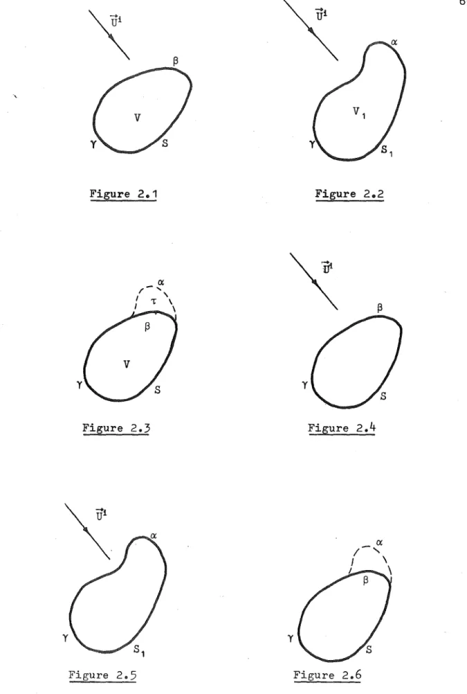
Consider a homogeneous isotropic body of permeability ~, permittivity E, and conductivity 0, occupying a volume V with surface S (Fig o 201), where
S=
sUYo
When the body is illuminated by an incident monochromatic
+i +
field U i (1029) - (1031) give the total field U
2 at any point as
+ + i
U
2
=
U +[[[v
P2
(V) G(kR)dvwhen
U
represents the electric field intensityE,
andwhen
U
represents the magnetic field intensityli.
Since the volume integration of (2.2) must include S, all terms-r
of P2 (v) involving the vector gradient operator are included in the integrand.
The field
U
2 can be determined using the PeCoRo technique by first treating two other problems.Problem (i)
Consider a body of permeability ~, permittivity £, and conductivity C5 occupying a volume VI with surface Sl
(Figo 202) f where
VI
=
VU
T,-ri
When the body is illuminated by the incident field U Q
-r
the total field U
l is given by (1 029) - (1031) as
-r
Pl(v) G(kR)dv,
-r
where Pl(v) is the polarization current density in Vlo
Problem (ii)
situated throughout the volume T (Figo 203) 0 The total field
U
at any point isU
=
-+ P(v) G(kR)dv, (20 7)P(v) being the polarization current density in Vo Notice that the source distribution [-Pl(v) ] contains no terms
involving the vector gradient operator across the surface 60 Adding the expressions in (206) and (207), and
using (20 5) gives
U
l +V
=
vi
+
fft
(20 8)where
-+ -+ -+
P3(v) =P(v) +Pl(v).
Comparison of (20S) with (202) shows that
(2010)
Thus the problem represented by the combination of
Figso 202 and 2 03 is identical to the problem represented by Figo 20 10 The polarization current replacement technique
is the method of determining the field
D2
by adding together the fieldsVI
andDo
2.1(b) SURFACE CURRENT REPLACEMENT
Consider a perfectly conducting closed body with surface S present in an incident monochromatic field
u
i(Fig. 2.4) 0 The total field
U
2 at any point is given by (1.29) and (1.32) as
UdfL
E(s) G(kR)ds
:+-where h(s}, the surface current density on S, is defined from (1.33) as
h(s)
=
and-+
n X H,
(2013)
-+
In order to evaluate U
2 using the S.C.R. technique, i t is first necessary to treat two other problemso
Problem (i)
Consider a perfectly conducting closed body with surface Sl' such that
(2 014 )
-+i
illuminated by the incident field U (Fig. 2.5)0 The
-+
total field Ul is given by (1033) as
7-1 ( s) G (kR) ds , (20 15)
Problem (ii)
Consider the surface S illuminated by the field
radiated by a surface current density [~1(s)] on a, which is external to S, as shown in Figo 20 60 The total field
D
is given bywhere £(s) is the surface current density on So
Adding (2015) and (2016), and using (2014), gives
VI
+U
=
vi
+
It
:+k ( s) G (kR) ds ,
where the surface current density k(s) is
k ( s )
=
f (
s )+
i (
s), on Y I'=
f(s) , onSince both S and Sl are perfectly conducting surfaces,
-+ -+
0, inside U
=
U2
=
Sf-+
Ul
=
0, inside Slo (20 19 )Thus, the problem represented by Figo 204 is identical
I
and from a comparison of (20 11) and (20 17)
:+ :+
h(s) == k(s) 0
Since the SoC.R. technique requires the solution of two problems in order to find the solution to a third, i t is, in general, a more protracted method of obtaining the field '{\ than solving the third problem directly. However, i f the solution
VI
to Problem (i) is knownexplicitly, only Problem (ii) remains to be solved. Because Problem (ii) has sources only in close proximity to the
scattering body, the total field external to an appropriate region can be completely described by a sum of outward
travelling waves. The use of such an expansion to represent the field enables the scattering from large or even infinite bodies to be determined with only the size'of the deformed
surface being limited by available computational facilities. To illustrate the use of the S.C.R. technique, i t
will be applied to the problem of determining the scattering from a perfectly conducting two-dimensional wedge with
deformed apex, for both magnetic and electric polarizations of the incident field. Problem (i) corresponds to the
problem of scattering from a, perfectly conducting undeformed wedge, and Problem (ii) corresponds to the problem of
is formulated for a three-dimensional bodyo Since
the deformed wedge to be considered in the next sections is two-dimensional, the vector operator {~} of- section 201 (b) becomes the vector operator {A} , and the three-dimensional Greens function G(kR) becomes the
two-dimensional Greens functiong(kR) 0 These operators and Greens functions are defined in section 102(a) 0 Although the scattering from the deformed wedge is determined only for plane wave inciqence, i t should be remembered that any incident field can be represented
83 by a superposition of plane waves o
202(a'} THE DEFORMED WEDGE (Electric polarization) Problem (i)
Consider the infinite perfectly conducting wedge in Figo 207 occupying the region
I
<t>I
~ X and illuminatedby an electrically polarized plane waveo Use is made of the vector potential notation
-r -r
l-lH
=
V X A, -r A=
zA, (2 022)where z is the unit vector in the z direction 0 The
. -r
symbol U used in section 2ol(b) is replaced in this
section by
A,
and the vector operator {A} reduces to the scalar operator ]10 The incident field, normalized sostrength, is given by
The field Al surrounding the wedge is given by (10 23) as
co
I
n=l
v
The symbol r is used to denote the distance from the apex of the wedge to a point on the wedge surfaceo The surface current density on the wedge can then be
defined, by using the expressions in (2~22) and (1033), as
+
I (r)
where the upper (lower) symbol refers to the wedge surface ~=X (~= 2~ -X) 0
Problem (ii)
generality, i t is possible to define the deformation
C3 as being the cross-sectional contour between (a,-X) and (a, X) 0
The surface current density on the surface~=X will be distinguished by the subscript 1, that on ~= 21f
-
X by the subscript 2, and that on C3 by the subscript 30 The field incident upon the deformed wedge· is radiated from the ctirrent distribution
[-1
(r) ] ,o
~ r .;$on ~
=
X and ~=
21f-Xo Writing"
=
zI (r) ,and using (2 024) with (2026), i t is readily deduced that
- 4v
=
+ kr 00L
n=l
The total field A(pg~) surrounding the deformed wedge is found from (2 016) to be
~
-4'-
t
F(c) H;2) (kR)dc+ jll
4
r
[1;1 (r)+
12( r )1
H~2)
(kR) dr,o
where R is the distance from the elemental con.tour dc
+ A
or drto (p,~), and F(c)
=
zF(c) is the z-directedsurface current density on Co
The use of Graf'S addition theorem for Bessel
functions14 enables the expression in (2029) to be expanded as
00
trn(kb)
[
A(b p¢)
=
=¥-
I
{Fl (r) cos[m(¢-x) ] m=-oo
+F2(r)cos[m(¢+x)J}H~2)
(kr) dr+
H~2)(kb)[[
{F1(r)cos[rn(o-xl]t
F2(r)cos[rn(o+x)]}Jrn(kr) dr
-[(II
(r) cos [m (o-X)] + 12 (r) cos [mH+x) ]}Jrn fkr) drThe representation of the total field given in (2030) is valid for all ¢, and may be written as a trigonometrical Fourier series on the circle p
=
bo Thus=
B+ + 2o
00
L
p=l
b ~
a,
where the B- are functions of bo The B- are extracted
p p
from (2031) by performing the integration 27T
A(b,¢)
~~~(p¢)
d¢. oUsing the property of any cylindrical Bessel function
e
(z) that14m
e (z )
=
(-1 ) me ( z )m -m
(2032)
(2,,33)
where m is any integer or zero, i t fo]ows from (2030) and (2 032) that
B~
=-iX [
~~~
(PX)[J
p (kb) [ [ Fl (r)
±
F 2 (r)lH~
2) (kr) dr+ H (2) (kb)
p
+ H(2) (kb)
P
f
b
a ,
cos
F
3(C)J P (kr) . S l n (p8) '
The sources of the field A(p,¢) are contained
(2034)
for p > a. A representation of the field which satisfies the radiation condition at infinity84 and the boundary condition (1.5) on the wedge surface is
<Xl
I
an_H~~)(kp) sin[nv(~-x)],
n=l
p > a, X ~ ~ ~ 27f:-X,
where the compleKcoefficients a n are yet to be determined. The surface current density on the wedge surfaces
r > a can be described in terms of the a by using (2035)
n
with (2.22) and (1.33). Then
00
1
F (r)
=
+-m kr \' L (±l)nnv an H(2) (kr) n v ' r > a, m
=
1 2°n=l
Because the total field inside the deformed wedge is
+
everywhere zero, the Fourier coefficients B- of the
p
field on the circle p
=
b are given bycos
A(b,~ s~n(p~) d~,
as an alternative to (2.32). Using (2.35) with (2037)
+
to obtain the B~ in terms of the an results in
00
II cos
TIK
sin (PX)I
n=ltv at
H~~)
(kb) 2 2 (tv) -pt
=
2n-lAfter noting from (2028) and (2.36) that
00
I I (r)
±
12 (r)--
-8vI
tv jtv Jt(kr)sin(tv~),
t 2n-lkr
=
2nn=1 v . .
(2039)
00
-2 (2 ) 2n-l
Fl (r)
±
F2 (r)-
I
tv tKr
atHtv (kr) f =2n n=1
(20 40)
equating the two descriptions of the B-+ in (2 034 ) p
and (2038) gives
00
I U
nIl at D tFP + ct,p
where
o
D
t,p
. t v
=
~
qt(PX)+
H(2) (kb)P
C!
=2
H C2) (kb)t,p 4 P
I
=
Yt ,p ' t=
2n-l 2n[
J
oo H(2) (kr) H(2) (kr)dr
J p (kb) b _·_t ... v--,-. .,... --r"';'P---.
-J
b
a
H~~)
(kr}J1?(kr) dr 2jH~~)
(k.b)J
+
· 2 2 'r 1T [ (tv) -p ]
J·,(kr) qt· (.p8).dc, p
00
(2042)
(2043)
a
Ii' tv . tv . ( ,',) J tv (kr) J; (kr)dr
L .. J sJ.n tv ' t ' . p . ,
n=1 r
o.
and
q2n-l (~)
=
cos (~) 0. h l ' h' 85 USlng t e re atlons lp
~
~ d .CJ-i+l(kz) Cv (kz) -Cfl (kz) Cv+l (k z) }
Cv(kZ)~ = - kZ{--~.---·--2~--~2~~~--- J-i - v
CJ-i(kz) Cv(kz)
+
fl
+
vwhere Cfl(kz), Cv(kz) are any two cylindrical Bessel
functions, and simplifying (2.42) with the use of Appendix 1 allows the expression in (2041) to be reduced to
00
I
at Dt + Ct = Yt 'n=l ,p ,p ,p
where
D
t,p
t
=
2n-l 2n,
- ka H
t( v 2
+) 1 (ka) J (ka) - H (2) (ka) J +1 (ka)j
p ~v p f
(tv)2 _ p2
C
t,p k
and
y
t,P
00
=
4v qt (PX)L
n=l. tv . ( ,I, )
tv J sln tv,/,
Jtv+l(ka) Jp(ka) - Jtv(ka) Jp+l(ka) (tv) 2 _ p2
J t (ka) J (ka)
1
_ v --,,----Ptv+ p
The qt(~) ~re defined in (2.45) I
P
is any positiveinteger or zero, and tv
t
po202(b) THE DEFORMED HEDGE (Magnetic Polarization)
Problem (i)
Consider the infinite perfectly conducting wedge in Figo 207 occupying the region I¢I ~ X and illuminated by a magnetically polarized plane wave. The symbol ,+ U
-+
used in section 20l(b) is replaced in this section by Hi
the magnetic field intensity, and the vector operator {A}
becomes (VX). The incident field is given by
-+
H
=
zH, (20 51)The field HI surrounding the wedge is given by (1.23) as
00
L
n=O
J (kp) cos[nv(¢-x)]cos[nVljJ],