Design & Development of Cooling Systems for Roll
Forming Machine
Aejaz Sayed1, Asst. Prof. Rajesh S. Kalase2, Kunal Patil 31, Onkar Hooda 4, Atul Shirke 5Shubham Tambe 6
1
(Maintenance Head, Klassic Wheels Ltd)
2, 3, 4, 5, 6
Mechanical Engineering Department, G. H. Raisoni College of Engineering and Management, Ahmednagar, Savitribai Phule Pune University
Abstract: Cooling of the job (work piece) is essential as if cooling is not done to the Roll forming machine there is increase in the temperature of the roller being used due to the friction between roller and the rim & also the rim which is being sent for the forming is being thermally expanded in its previous operation so its temperature is more which is transferred to the roller. So there is deformation and undercut of the roller. As coolant splashes on the floor so there was no provision for the cooling system. So the casing is designed for the roll forming machine to avoid splashing of coolant, friction between roller and rim. Automation concept is used by introducing PLC. Hydraulic system with pumps & motors, so that heat generation during forming operation will be minimized which will result in improvement of roller life & overall productivity will increase. Also the cleaning operation of the rim would be eliminated. The rim which is hot would be cooled down so increasing the safety of the worker working on that machine.
Keywords: Roll Forming, PLC, Pneumatic cylinder, coolant, casing
I. INTRODUCTION
Roll Forming is type of rolling which involves continuous bending of long strip of sheet metal into desired cross- section. Strip is then passed through set of rollers until desired profile is obtained. Roll Forming Machines are available that produce shape of different size and material thickness using the same roll. Variation in size is achieved by making the distance between the rolls, variable by manual adjustment or computerized control allowing for rapid changeover. The specialized mill are present in the light gauge framing industry where metal studs and tracks of standardized profile & thickness. The roll forming machine is being manufactured by ‘Jaya Hind Sciaky Ltd’, Pune. Cold forming is the operation used for manufacturing of rim. In roll forming two or more rollers are used without addition of any heat.
Roll forming machines are available that produce shapes of different sizes and material thicknesses using the same rolls. Variations in size are achieved by making the distances between the rolls variable by manual adjustment or computerized controls, allowing for rapid changeover. These specialized mills are prevalent in the light gauge framing industry where metal studs and tracks of standardized profiles
The Roll Forming Machine is being manufactured by the “JAYA HIND SCIAKY LTD, a company from Pune, which is a joint venture of Kinetic Engineering & Sciaky Ltd, France. Before Forming is being done the various operations done on the metal sheet is as follows.
1) Sheet is being bent in a circular shape
2) Then the circular metal sheet is being welded by using two welding operations viz butt welding & Spot welding 3) Then knipping of the unwanted welded portion is being done
4) Then the circular metal sheet is being thermally expanded & given a specific curvature shape to it
5) Then the forming operations are being done on the circular metal sheet, it is being done in 3 stages viz 1st forming, 2nd forming & 3rd forming.
6) Then they formed round metal sheet (Rim) has a tapered hole made from where tube valve can be inserted. 7) Then the round metal sheet is being visually inspected
8) Then again CO2 welding is being done, where the metal plate manufactured in the press shop is assembled here with the round metal sheet.
II. LITERATURE SURVEY
Youngyun Woo, et.al [1]: They stated that the metal sheet of various cross section profiles like profile for automotive railway, sheet construction, building industries, etc are being studied. Two sheets are being joined together by adhesive material. Here the two layers are used of SPCC and AL5052 material. The bend angle of roll form blank decreased. When the combination is changed from SPCC+ AL5052 to AL5052+SPCC. The longitudinal bow height increases in order of concave, trapezoidal and convex shape. William Ion, et.al [2]: In this paper the author says that cold roll forming is an incremental sheet forming process, which offers a wide range of advantages. The material used for sheet metal is UHSS (Ultra High Speed Steel). Here two profiles are being studied. i) v-section ii) flat strip with the rim. Here as number of passes increases, the length of sheet also increases.
Aromal kannan, et.al [3]: In it different natural oils like castor oil, palm oil, rice ban oil, sesame oil, sunflower oil, etc are being studied for their coolant action on cutting. They have stated the property of vegetable oil that they have higher boiling point and greater molecular weight and this result in less loss due to vaporization and misting. Also the temperature is not much as compared to conventional cutting fluids. Also the roughness is reduced by using natural oils. Natural oils for using as coolant are being checked for output parameters like cutting force, tool wear and tool life.
Zinat Ara Nisha, et.al [4]: In it they have explained that minimum quantity of lubrication, they have carried out analysis regarding machining cost and they have stated that 15% of total machining cost is spent on cutting fluid. In this they have used temperature sensors for their experiment. When temperature is less than 40oC for the turning operation on lathe then according to the setup the solenoid valve which makes the coolant flow on the workpeice is in closed state and when it becomes equal to 40oC then the solenoid valve opens for 2 seconds and when temperature exceeds 40oC , then solenoid valve is continuously open and cutting fluid flows continuously. Also due to intelligent cooling, surface roughness is more, also tool life reduces a bit as compared to flood cooling but wastage of coolent is comparatively very less as compared to flood cooling. If intelligent cooling system is brought in operation then machining cost reduces as coolant cost reduces.
Junsong Jin, et.al [5]: In this paper finite element analysis is done on the rotary forming process of rim. In this paper they have compared experimental study and observations with the FEA calculations. They have made FEA calculations on rolling of upper roller surface, lower roller surface as well as arc bottom surface. The rotary forming process for thickening of rim is divided into three parts: i) Elastic Bending ii) Roller Groove Filling iii) Flash Forming.
WANG Hai-tao, et.al [6]: Explains that Speed and working condition of the Piston has effect on friction force. By the setup as the speed increases friction force also increases to some extent and then reduces gradually. Stroke length doesn’t have any effect on friction force. It is independent of stroke length. As pressure of compressor air increases, friction force also increases for same stroke length of piston cylinder arrangement. Friction Force varies with working condition of piston. When piston is stationary friction force is high.
III. METHODOLOGY
The manufacturing of the casing includes the different operations performed on the raw material. The sheet metal is cut into required size by the process of shearing and shearing machine is used for this purpose. This is used because it is the most economical method for sheet metal cutting and the accuracy requirement is not that high .After the cutting of sheet metal for different parts of the casing the joining of the various parts is to be done.
The upper casing is also divided into two parts, the upper front and the upper back. Hinges are provided at the top of the two casings. The front top rotates about the hinge in 180 degree so that the machine inside the casing will be accessible for the maintenance. Then all the sub-assemblies are combined and casing is complete.
IV. COMPONENTS OF COOLING ARRANGEMENT
A. Casing
FIG: CASING
1) Casing is basically an enclosure. It separates the machine from the surroundings.
2) It avoids the danger to the operator and chances of accidents. It avoids the dust and the dirt to get into the machining process. 3) This also serves for a place to mount other things like control panels and different gauges and other things.
4) This casing has divided into 3 parts. The lower half which stores the coolant. The upper back half which has space for accommodation for hydraulic pipes.
5) The front upper half which has the front door cut-out for easy inserting and removal of the rim. The upper and lower half’s are joined by bolts. The upper half has studs for easy alignment of the two halves.
B. Pneumatic Cylinder Arrangement
Fig: Pneumatic Cylinder Arrangement
1) Pneumatic cylinders are used for a faster opening and closing of the door. Two cylinders with cushioning are used for avoids the sudden impact on extension and retraction.
2) The cylinders have approximately 650 mm stroke lengths.
3) The upper portion of the piston rod has an extension provided which can be adjusted as per the opening area of the door required.
4) The extension has a rectangular plate provided for the mounting of the glass door. The plate along with the glass moves with the piston.
C. Stand
Fig: Stand
1) It’s used to avoid the contact between the coolant and the lower surface of the machine.
2) Serves the purpose of dampening and absorbing the vibrations of the machine and also transmits the weight of the machine evenly to the ground
D. Coolant Tank
FIG: COOLANT TANK
1) The coolant reservoir is a tank that contains the excess coolant. It receives the coolant from the main tank via a pump.
2) This tank is provided with the filtering mechanism which filters the coolant and separates the unwanted particles, dust and dirt.
E. Pumps
1) Coolant pumps are used for the pumping the cooling lubricants from the coolant reservoir.
2) It pressurizes the coolant so that the dirt and the debris can be easily removed from the rim and the roller.
3) They are multistage, centrifugal pumps that are designed to be placed in the liquid that is to be pumped, and as such they are fully submersible. They are safe for use with both water and water-soluble coolants.
4) Two pumps are used. A low pressure for pumping the coolant from the primary tank to secondary tank.
5) High pressure pumps for pumping the coolant at high pressure to the rolling area so that the unwanted particles can be removed easily. Nozzles are used for directing the stream of coolant onto the rolling area.
F. PLC (Programmable Logic Controller)
FIG: PLC
1) A programmable logic controller (PLC) or programmable controller is an industrial digital computer which has been ruggedized and adapted for the control of manufacturing processes, such as assembly lines, or robotic devices, or any activity that requires high reliability control and ease of programming and process fault diagnosis.
2) They were first developed in the automobile manufacturing industry to provide flexible, ruggedized and easily programmable controllers to replace hard-wired relays, timers and sequencers. Since then they have been widely adopted as high-reliability automation controllers suitable for harsh environments.
3) A PLC is an example of a "hard" real-time system since output results must be produced in response to input conditions within a limited time, otherwise unintended operation will result.
V. PROPOSED DESIGN
FIG: PROPOSED DESIGN
VI. DESIGN CALCULATIONS
A. Volume of Coolant in Casing Vc = Length*Breadth*Height (m3) = 1.2*1*0.162
B. Volume of Coolant in Collecting Tank VT = Length*Breadth*Height (m3) = 0.5*0.6*1
= 300 litres
C. Pneumatic Cylinder
Standards Available …. (SMC Pneumatics) (Cylinder) bore size (D) = 32 mm Piston rod= 12 mm
Piston area=804 mm
Assume operating pressure 0.5-0.65 N/mm2 Force (extension) = p*(π/4)*d2
=0.5*(π/4)*12 =60 N
Force (retraction) = (π/4)*(D2)-(d2) = (π/4)* (162)-(122) = 345 N
D. Coolant Flow Rate Q = Area * Height/Time = (π/4)*1.92*(200/8) = 70.88 cm3/s = 4.25 litres/ min = 1.1227 gallons/minute
E. Pump Horse Power HP = (Q*H)/39.60 = (1.1227* 6.5616) = 0.18
Where Q= Discharge in gallons/minute H= Head in foot
VII. OBSERVATIONS
TABLE I PRODUCTION BEFORE EXPERIMENT
Shift 1 Shift 2 Shift 3 Total Rejection
Day 1 1300 1200 930 3430 177
Day2 1280 1240 940 3460 155
Day3 1320 1240 960 3480 158
Day4 1310 1240 980 3540 172
Day5 1290 1250 990 3530 165
Day6 1270 1200 940 3410 159
Day7 1290 1190 950 3430 180
Day8 1320 1250 930 3500 169
Day9 1300 1180 930 3410 168
Day10 1300 1190 940 3430 175
Day11 1280 1220 930 3430 176
Day12 1260 1230 920 3410 164
Day13 1290 1250 960 3500 150
Day14 1310 1200 930 3440 152
Day15 1320 1210 940 3470 172
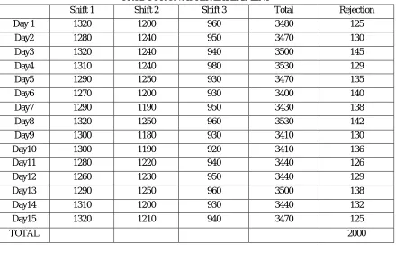
TABLE II
PRODUCTION AFTER EXPERIMENT
Shift 1 Shift 2 Shift 3 Total Rejection
Day 1 1320 1200 960 3480 125
Day2 1280 1240 950 3470 130
Day3 1320 1240 940 3500 145
Day4 1310 1240 980 3530 129
Day5 1290 1250 930 3470 135
Day6 1270 1200 930 3400 140
Day7 1290 1190 950 3430 138
Day8 1320 1250 960 3530 142
Day9 1300 1180 930 3410 130
Day10 1300 1190 920 3410 136
Day11 1280 1220 940 3440 126
Day12 1260 1230 950 3440 129
Day13 1290 1250 960 3500 138
Day14 1310 1200 930 3440 132
Day15 1320 1210 940 3470 125
TOTAL 2000
VIII. RESULTS AND DISCUSSION
A. Casing being done so splashing of the coolant is being avoided B. Roller life increased due to application of coolant
C. Machine is brought under automation. D. Safety of the operator improved E. Rejection of the Rims Reduced
IX. CONCLUSION
At last of this paper we conclude that the project on Design and Development of Cooling system for Roll Forming Machine was carried out successfully. This project helped the company to increase their productivity in enormous forms like safety of the operator, implementation of 5s Culture, Poka Yoke, kaizen, rejection control and optimum utilization of available resources. Also Cleanliness of the floor space increased to a greater extent
X. ACKNOWLEDGEMENTS
Inspiration and guidance are invaluable in every aspects of life especially in the field of academics, which we have received from our Prof. Kalase R. S. (Project Guide) and Mr. Sayed (Company Guide, Klassic Wheels Ltd.) who has shown us right throw in various stages of project. We should like to thank to Prof. Kalhapure A. S. (Project Co-ordinator), Prof. Kalase R. S. (Head of department) and Dr. Jaykumar Jayaraman (Principal) for providing us with all required facilities and necessary support.
REFRENCES
[1] Youngyun woo, Pilgyu kang, Ilyeong oh, Younghoon moon, ‘Flexible roll forming of double layered blank’, Science direct, pp.776-781, 2018 [2] Kwan sing tsang, William ion, ‘industrial validation of strain in cold roll forming of UHSS’, Science direct, pp.789-795, 2018
[3] Aromal kannan, Tony gin, ‘Study of new vegetable oil based eco-friendly cutting fluid for machining operation, IJSR, pp.289-294, 2015 [4] AHM Faizle Elahi Zinat Ara Nisha, Imam -ol-Ferdous, ‘Intelligent cooling system for machining, ICMERE, 2015
[5] Xinyun Wang, Lanli lei deng, Junsong Jin, Yunzhan Hu, ‘Effect of forming parameters on sheet metal stability during rotary forming processes for rim thickness, Science direct, pp.264-273