A Novel Joint Scheme of PAPR Reduction and BER
Performance Enhancement in Interleaved DCT-SCFDMA
System
Rokeya Jahan Mukti
Department of Physical & Mathematical Sciences Chattogram Veterinary and Animal Sciences University
Chattogram, Bangladesh
ABSTRACT
This paper is concerned with the performance improvement of peak-to-average power ratio (PAPR) reduction in interleaved mode of discrete cosine transform based single carrier frequency division multiple access (DCT-SCFDMA) using a combined technique of pulse shaping with a nonlinear companding process. This proposed scheme is based on the modified hyperbolic tangent transform which can compress the large signals and enlarge the small signals while keeping the average power invariant. Simulation results show that the proposed methodology markedly reduces the PAPR value and enhances the bit error rate (BER) performance.
Keywords
Peak-to-average power ratio, pulse shaping, hyperbolic tangent, companding, DCT-SCFDMA.
1.
INTRODUCTION
In single-carrier frequency division multiple access (SC-FDMA) scheme, modulated signals have a much smaller PAPR compared to other multicarrier modulations. In a single carrier system, pulse shaping is required to band-limit the transmit signal [1] that enlarges the PAPR of SC-FDMA. As a result, a trade-off between PAPR reduction and spectrum efficiency is needed in conventional single carrier systems. Therefore, over the last several years research has been ongoing trying to design a pulse shaping filter which limits the PAPR without degrading the system performance based on the knowledge that, compared to other PAPR reduction techniques, pulse shaping is an effective and simple method. In case of SC-FDMA, several novel methods have also been introduced to handle the PAPR problem.
A novel pulse shaping filter with a new parameter β independent from the roll-off factor α is presented in [2]. This proposed filter increases the complexity of the system while maintaining the same excess bandwidth and the zero inter-symbol interference condition. A few bit errors are introduced to modify the few complex modulated symbols of each data SC-FDMA symbol in a sub-frame is proposed to reduce the PAPR but the BER performance is slightly degraded [3]. Jinwei et al. proposed a method, where a set of weighting windows with zero excess bandwidth is designed and finally candidate signal block with the lowest PAPR is selected to be transmitted [4]. In this methodology, side information is not required for data detection at the receiver and potential to be applicable in SC-FDMA systems with high order modulations. Above all this, the complexity of this system is increased. In [5], a hybrid scheme is presented where it combines the absolute exponential companding method with standard pulse shaping filter. In that method, PAPR of the DCT-SCFDMA system is significantly reduced for both
interleaved and localized mode of subcarrier allocation. Moreover, BER performance is also improved noticeably.
In this paper, a modified HT companding scheme is combined with conventional pulse shaping filter which shows more efficaciousness in PAPR reduction than the standard pulse shaping filter when used alone in interleaved DCT-SCFDMA system. Simulation results exhibits the effectiveness and robustness of the proposed scheme in terms of PAPR reduction and bit error rate performance.
The outline of the paper is organized as follows. At first, DCT-SC-FDMA system model is analyzed in section II. In section III and IV, the mathematical analysis of PAPR and the brief background regarding pulse shaping is discussed. Proposed joint scheme is described in section V. To evaluate the performance of the proposed scheme, simulation parameters and results are shown in section VI. The last section concludes this article.
2.
PAPR OF SC-FDMA SIGNALS
SC-FDMA, a special case of “linearly pre-coded” orthogonal frequency division multiple access (OFDMA), is the combination of SC-FDE and FDMA system where the envelope fluctuations are less pronounced than that of the OFDMA system. Due to the precoding, SC-FDMA has relatively lower PAPR than OFDMA [6]-[7], which minimizes the cost and increases the power efficiency of a transmitter’s power amplifier. For the downlink communication, a larger PAPR may not be problem but in case of uplink it means a lot. That’s why SC-FDMA is employed in the LTE uplink. For this, complicated frequency domain equalizers are required only at base stations and not at mobile terminals [8]. At mobile terminals employing SC-FDMA, the power amplifiers can be simpler and more power-efficacious than they would be with OFDMA transmission [9], though the equalizer of an SC-FDMA system is far more perplexed than an OFDMA system.
The analytical expression for PAPR is defined as follows for the transmit signal
x
(
t
)
.
T M
T M t
dt t x T M
t x
PAPR ~
0 2
2 ~ 0
~ 1
max
(1)
2
1 0 2 2 1 ,...., 1 , 0 0~
1
~
max
M m m m Mx
M
x
PAPR
(2) [image:2.595.69.266.229.418.2]The total PAPR at the transmitter is determined by the combination of the modulation and the pulse shaping filter. The filter’s PAPR depends on the excess bandwidth mask and the number of symbols covered by the filter [10]. For any pulse shaping filter applied to the system, the PAPR will increase if the number of symbols is augmented and the excess bandwidth is reduced. Windowing might be useful to reduce the filter length needed for a given stop band attenuation.
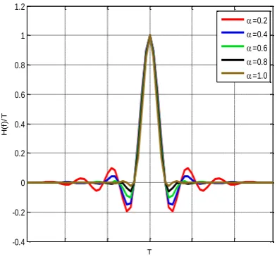
Fig 1 :Impulse response of the RC filter
The impulse response of the channel must satisfy the Nyquist-I criterion to be able to transmit data within a band-limited channel without inter-symbol interference [11]. A pulse h(t) that meets the Nyquist criterion and is said to have zero ISI is described as follows [12]-
,...
2
,
1
,
0
0
,
1
k
k
kT
h
(3)Where, k is the symbol time index and T is the symbol period. The frequency characteristic of Eq. (3) is expressed as follows
1
1
mT
m
f
H
T
(4)where H(f)is the Fourier transform of h(t).
The universal pulse that satisfies Eqs. (3) and (4) is the conventional raised-cosine (RC) filter, which has the following spectral magnitude [16]-
T f T f T T f T T T f T f HRC 2 1 , 0 2 1 2 1 , 2 1 cos 1 2 2 1 0 , (5)The conventional raised-cosine (RC) filter is assumed to have a linear phase. The roll-off factor α, which ranges between 0 and 1, is the variable that determines the filter bandwidth
1
2T .B
The corresponding impulse response shown in Fig.2 is obtained by taking the inverse Fourier transform of Eq. (5), and it is given as follows-
2 2
4
1
cos
sin
c
h
(6)where
is the normalized time, equal to
t T.The square root raised-cosine (SRRC) filter is an implementation of a low-pass Nyquist filter, i.e., one that has the property of vestigial symmetry. Spectral magnitude of RRC filter is,
f
H
f
H
RRC
RC (7)The impulse response of this filter is given by [13]-
2 2
16
1
1
cos
.
4
1
sin
h
(8)3.
PROPOSED SYSTEM MODEL
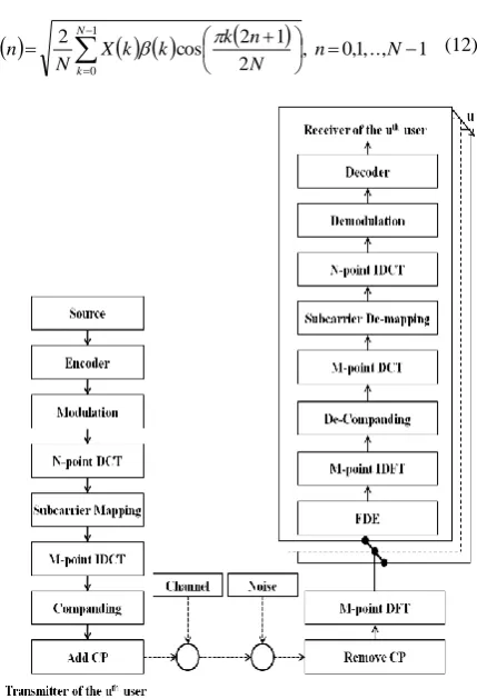
Real arithmetic only used in Discrete Cosine Transform which reduces the signal processing complexity at great extent [14]. It shows large energy compaction property [15], which leads to a reduction in the effect of ISI while the DFT processing still uses complex arithmetic and suffers from imbalance problem. A schematic diagram of the proposed DCT-SCFDMA system is depicted in Fig. 1.
Spectral efficiency and length of the CP are same in both the DCT-SCFDMA and the DFT-SC-FDMA system. In DCT, a single set of co-sinusoidal functions , where
and is used. The minimum required to satisfy the orthogonality
condition
nf
t
dt
k
k
n
n
T
t
kf
T
T
o
0
,
,
1
2
cos
2
2
cos
2
(9)
is 1T.
At time instants T(2n1) 2N, sampling the continuous-time signal gives a discrete-continuous-time sequence after the discrete cosine transform [14] as follows:
,
0
,
1
,
..,
1
2
1
2
cos
2
1 0
N
k
N
n
k
n
x
k
N
k
X
N n
(10) Where,
nx denotes the nth sample of the input signal and
1 ,.... 2 , 1 , 1 0 , 2 1 N k k k (11)
After the inverse DCT (IDCT), the discrete-time signal can be written as [15]:
, 0,1,.., 1 21 2 cos 2 1
0
N n
N n k k k X N n x
N
k
[image:3.595.60.275.65.380.2] (12)
Fig 2 :Block Diagram of the proposed DCT-SCFDMA
transciever
The discrete time signal are then transformed into a signal using the companding process based on the modified hyperbolic tangent (HT) function to reduce the magnitude of signal peaks. This companding technique adjusts the both small and large amplitude of signals while keeping the average power at same level. This section has been carried out by the following modified HT function over the x
n signal-(13)
Where, k is the companding parameters that controls the companding level. After the companding process, pulse shaping has been done over the uniformly distributed discrete time signals. The impact of this process has been studied by using the standard raised cosine filter and square root raised cosine filter separately and termed as R1 and R2 respectively.
At receiver section, the inverse function of HT is used to expand the received signals is expressed as follows
) ( tanh
) (
1
1
x sign k
x a x f
y
(14)
4.
SIMULATION PARAMETERS AND
RESULTS
In this section, the investigations of the BER and PAPR of the DCT IFDMA signals using Minimum Mean Square Error (MMSE) equalizer have been done to verify the effectiveness of this method. Table-1 illustrates the parameters implemented in the simulation for the DCT SC-FDMA system using interleaved subcarrier allocation.
Table 1. Parameters used in Simulation
Parameter Value
Transmission Bandwidth 5MHz
Modulation QPSK, 16QAM, 64QAM
Number of Subcarriers 512
Input Data Block Size 128
Spreading Factor, Q 4
Subcarrier Allocation Interleaved
Equalization MMSE
Subcarriers Spacing 9.765625KHz
4.1
BER Performance
At a certain BER=10-4, it observed that, the performance gain is better for the proposed DCT-SCFDMA system over the DCT-SCFDMA system modeled in [16] when the QPSK modulation scheme has been adopted for interleaved subcarrier allocation. The desired symbol suffers less interference coming from neighboring symbols in proposed DCT-SCFDMA system. Thus, the inter symbol interference is reduced in the system, which in turns reduces the BER.
In SCFDMA, interleaved mode is more preferable than the localized mode in terms of power efficiency and PAPR. Fig. 3 illustrates the BER performance of the DCT-SC-FDMA using a vehicular-A outdoor channel [17] with different subcarriers mapping schemes. It can be observed that the proposed interleaved DCT-SCFDMA system provides a significant BER performance improvement over the conventional DCT-IFDMA for QPSK while the performance has been degraded for localized mode of subcarrier allocation adopting our proposed system. At a BER=10−4 with QPSK, the performance gain is about 3dB for the proposed DCT-IFDMA system when compared to that with conventional DCT-IFDMA system.
4.2
PAPR Reduction
Extensive simulations in MATLAB have been carried out using QPSK, 16-QAM and 64QAM modulation schemes for DCT-IFDMA system which are applied in the 3GPP LTE uplink. The evaluation of PAPR reduction performance of the proposed system has been carried out for a bandwidth allocation of 5MHz, 512 system’s subcarriers (N) and 128 user’s subcarriers(M); therefore, the spreading factor is Q=N/M=4. To show the PAPR analysis of our proposed method R1 (RC filter with modified HT) and R2 (SRRC filter
with modified HT), data are randomly generated. After calculating the PAPR of each block, the data is presented as an empirical Complementary Cumulative Distribution Function (CCDF), which measures the probability for which the signal’s
PAPR exceeds a certain threshold
[18].
0
0 P PAPR PAPR
[image:3.595.318.538.86.247.2]4
Fig 3 :Comparison of BER performance between
[image:4.595.333.527.78.263.2]different subcarrier mapping of DCT-SCFDMA system using QPSK.
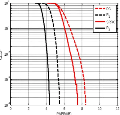
Fig 4 :CCDF of PAPR for DCT-IFDMA system using
[image:4.595.314.542.448.574.2]QPSK and α=0.35.
Fig 5 :CCDF of PAPR for DCT-IFDMA system using
16QAM and α=0.35.
Fig 6 : CCDF of PAPR for DCT-IFDMA system using
64QAM and α=0.35.
In wireless communications pulse shaping filters are widely used for avoiding ISI. Wireless communication systems implement roll-off factors
in the range of 0.22<
<0.5 [19]. For most of the simulations, we used roll-off factors of 0.35, which are typical roll-off factors used in literature. The effect of the proposed method on the PAPR performance in the DCT-IFDMA system has been studied and the results are shown in Fig. 4, 5 and 6. From these figures, it is obvious that the DCT-IFDMA system has a lower PAPR using our method than that of the DCT-IFDMA system adopting pulse shaping filter alone.Table 2. PAPR Comparison Between the Proposed
Methods (R1 and R2) and the System using Pulse Shaping
Filter employing Different Modulation Scheme
PAPR Reduction
Method
PAPR of DCT-IFDMA (dB)
QPSK 16QAM 64QAM
RC 5.4 7.7 8.5
R1 5.3 5.4 5.5
SRRC 4.1 6.7 7.6
R2 4.1 4.3 4.4
In Fig.4, it shows that the sytem performs almost same PAPR value for QPSK modultaion format using proposed methodology when it compared to the system using pulse shaping filter only. Though there is no major improvement in PAPR dilution, BER performance is improved noticeably for QPSK.
However, in terms of higher order modulation scheme- 16QAM and 64QAM, our method achieves significant improvement in PAPR reduction. Fig.5 extends the simulation for DCT-IFDMA system using 16QAM modulation where proposed methods R1 and R2 has lower PAPR compared to
that of the RC filter by about 2.3dB and SRRC filter by about 2.4dB. For 64QAM modulation format, R1 and R2
outperforms the conventional pulse shaping filters. In case of R1 method, the system achieves 3dB gain while for R2, it
0 5 10 15 20 25 30 35
10-4 10-3 10-2 10-1 100
SNR (dB)
BER
DCT-IFDMA Proposed DCT-IFDMA DCT-LFDMA Proposed DCT-LFDMA
0 2 4 6 8 10 12
10-4 10-3 10-2 10-1 100
PAPR(dB)
CCDF
RC R1 SRRC R2
0 2 4 6 8 10 12
10-4 10-3 10-2 10-1 100
PAPR(dB)
CCDF
RC R1
SRRC R2
0 2 4 6 8 10 12
10-4 10-3 10-2 10-1 100
PAPR(dB)
CCDF
[image:4.595.70.266.535.706.2]achieves 3.2dB gain over RC and SRRC filter respectively as shown in Fig.6
The effectiveness of the proposed system over standard pulse shaping filter is tabularized in Table 2. It is obvious from Table 2 that, R1 and R2 has lower PAPR for 16QAM and
64QAM modulation than the RC and SRRC filter respectively in DCT-IFDMA system.
5.
CONCLUSIONS
In this paper, a new joint scheme is presented for interleaved mode of DCT based SCFDMA system. Simulation results have shown that, the proposed system has lower PAPR for 16QAM and 64QAM modulation format than the standard pulse shaping based DCT-IFDMA system. Additionally, the BER performance of the system using QPSK is also improved to a great extent. It can also be used together with the recent probabilistic pulse shaping methods to further reduce the PAPR with very low additional system complexity. Due to better PAPR reduction performance and improved bit error rate in the proposed scheme, it can be a profoundly use in practical SCFDMA system, especially in those with higher order modulation.
6.
REFERENCES
[1] Huang, G.; Nix, A.; and Armour, S., “Impact of radio resource allocation and pulse shaping on PAPR of SC-FDMA signals,” IEEE 18th International Symposium on PIMRC, pp. 1–5, September 2007.
[2] Azurdia-Meza, Cesar A.; Lee, Kyujin and Lee, Kyesan; “PAPR Reduction in Single Carrier FDMA Uplink by Pulse Shaping Using a β-α Filter,” Wireless Personal Communications, vol. 71, no. 1, pp. 23-44, July 2013. [3] J. Ji, G. Ren and H. Zhang, “PAPR reduction in coded
SC-FDMA systems via introducing few bit errors,” IEEE Communication Letters, vol. 18, no. 7, pp. 1258-1261, July 2014.
[4] Ji, J.;Ren, G. and Zhang, H., “PAPR Reduction of SC-FDMA Signals via Probabilistic Pulse Shaping,” IEEE Trans. on Vehicular Technology, vol. PP, no. 99, pp. 1, October 2014.
[5] Md. Rabiul Hossain, Kazi Tanvir Ahmmed, “Efficient PAPR Reduction in DCT-SCFDMA System Based on Absolute Exponential Companding Technique with Pulse Shaping,”Wireless Personal Communications, vol. 97, no. 3, pp. 3449-3463, December 2017.
[6] Cruz-Roldan, F.; Dominguez-Jimenez, M.E.; Vidal, G.S.; Amo-Lopez, P.; Blanco-Velasco, M.; Bravo-Santos, A., “On the use of discrete cosine transforms for multicarrier communications,” IEEE Trans. on Signal Processing, vol. 60, no. 11, pp. 6085-6090, July 2012. [7] M. Rinne; M. Kuusela; E. Tuomaala; P. Kinnunen; I.
Kovacs; K.Pajukoski and J. Ojala, “A performance
summary of the Evolved 3G (E-UTRA) for voice over Internet and best effort traffic,” IEEE Trans. Veh. Technol., vol. 58, no. 7, pp. 3661-3673, Sep. 2009. [8] Myung, H. G., Lim, J., & Goodman, D. J.,
“Peak-to-average power ratio of single carrier FDMA signals with pulse shaping,” IEEE 17th International Symposium on PIMRC, pp. 1–5, Sept. 2006.
[9] J. Ji and G. Ren, “A new modified SLM scheme for wireless OFDM systems without side information,” IEEE Signal Process. Lett., vol. 20, no. 11, pp. 1090-1093, Nov. 2013.
[10] Chatelain, B. and Gagnon, F., “Peak-to-average power ratio and intersymbol intersymbol interference reduction by Nyquist pulse optimization,” IEEE 60th Vehicular Technology Conference, vol. 2, pp. 954–958, Sept. 2004. [11] Scanlan, J. O. (2007). Pulses satisfying the Nyquist
criterion. Electronics Letters, 28(1), 50–52.
[12] Mohapatra, S. and Das, S., “Peak-to-average power reduction (PAPR) by pulse shaping using a modified raised cosine filters,” Annual IEEE India Conference, pp. 1–4. Dec. 2009.
[13] T. S. Rappaport, Wireless Communications Principles and Practice, 2nd ed., Pearson Education, Indianapolis, IN, 2002.
[14] P. Tan and N. C. Beaulieu, “A comparison of DCT-based OFDM and DFT-based OFDM in frequency offset and fading channels,” IEEE Trans. Commun., vol. 54, no. 11, pp. 2113–2125, November 2006.
[15] A. V. Oppenheim; R. W. Schafer and J. R. Buck, Discrete-Time Signal Processing, 2nd ed., Prentice Hall, Upper Saddle River, NJ, 1999.
[16] Al-Kamal, F. S., Hassan, E. S., El-Naby, M. A., Shawki, F., El-Khamy, S. E., Dessouky, M. I., Sallam, B. M., Alshebeili, S. A., & El-samie, F. E. A., “An efficient transceiver scheme for sc-fdma systems based on discrete wavelet transform and discrete cosine transform,” Wireless Personal Communications, vol. 83, pp. 3133–3155, 2015.
[17] 3rd Generation Partnership Project and 3GPP TS 25.101, “Technical Specification Group Radio Access Network; User. Equipment (UE) Radio Transmission and Reception (FDD). (Release 7), Section B.2.2,” September 2007.
[18] Nee, R. V., and Prasad, R., “OFDM for wireless multimedia communications. Boston,” Massachusetts: Artech House, 2000.