Effect of Pass Strain on Grain Refinement in 7475 Al Alloy during
Hot Multidirectional Forging
Oleg Sitdikov
1;2, Taku Sakai
1, Alexandre Goloborodko
1, Hiromi Miura
1and Rustam Kaibyshev
2 1Department of Mechanical Engineering and Intelligent Systems, The University of Electro-Communications, Chofu 182-8585, Japan 2Institute for Metals Superplasticity Problems, Khalturina 39, Ufa 450001, Russia
Effect of pass strain (") on grain refinement was studied in multidirectional forging (MDF) of a coarse-grained 7475 Al alloy at 490C
under a strain rate of3104s1. Samples of rectangular shape were deformed up to accumulated strains of around 6 with subsequent changes
in loading direction 90from pass to pass. The pass strains in each compression (") were 0.4 and 0.7. The cumulative flow curves integrated by
each compression exhibit significant work softening just after yielding, followed by apparent steady state plastic flow at high strains. Structural changes were characterized by grain fragmentation due to frequent development of deformation and/or microshear bands followed by full evolution of new fine grains in the original grains. Increasing"accelerates significantly the kinetics of grain refinement, leading to more clear reduction of flow stresses at moderate to high strains. MDF of"¼0:7results finally in formation of a finer grained structure with an average size of around 7.5mmat strains of above 3.5, while, the processing with"¼0:4develops a slightly coarser grain structure at higher strain of about 6. The effect of MDF on new grain evolution and the mechanisms of grain refinement are discussed in details.
(Received January 20, 2004; Accepted March 18, 2004)
Keywords: grain refinement, multidirectional forging, aluminum alloy, shear band, grain boundary sliding
1. Introduction
Recent investigations have shown that there is a great potential for extraordinary improvements in the chemical, physical and mechanical properties of many metals and alloys by refining their grain structure through severe plastic
deformation (SPD) to (sub)micron to nanocrystalline level.1)
Several techniques,e.g.equal channel angular extrusion,1–8)
torsion under high pressure,1,4,7) multidirectional forging
(MDF)1,4,9–14)etc., are available for subjecting materials to
ultra-high strains required to develop such fine grain structures. MDF seems to be especially attractive in these various SPD methods, because it is the easiest method without any special device and has great potentiality for scaling up of relatively large samples that can be suitable for industrial applications. This SPD technique can also be a very valuable scientific tool for studying the microstructure
development in large strain deformation.4,10–14)
The principle of MDF, i.e. multidirectional forging
operation, is repeating compression process with changing
the axis of the applied strainx!y!z!x!. . .at each
step. Redundant plastic strains can be accumulated into the material as it is repeatedly deformed at ambient to elevated temperatures. Since a work piece changes hardly its shape under MDF conditions, many repetitive passes can be undertaken to achieve very high total strains. It has been
shown recently13)that such strain accumulation applied from
various directions becomes very important for evolution of equiaxed fine grains and so the grain refinement. At the same time, grain refinement during interrupted deformation may be controlled not only by total strain accumulated, but also by a
strain per each pass.3) There are, however, almost no
experimental data on this effect in MDF, as far as the authors know.
The main aim of the present work was to study any influence of the value of pass strain (") on grain refinement during hot MDF. The 7475 Al alloy was used as one of the
commercial-base materials showing continuous dynamic
recrystallization (cDRX) during hot deformation.13–15) The
microstructural evolution taking place during MDF with a step strain of 0.4 (hereafterMDFof"¼0:4) is described
elsewhere.13)The current work analyzed the data obtained by
MDFof"¼0:7 comparing with the results of"¼0:4. The effect of step strain on microstructural development and the grain refining mechanisms operating during hot MDF are discussed in details.
2. Experimental
The material tested was an as-cast 7475 Al alloy with the
following chemical composition:
Al-6%Zn-2.5%Mg-1.8%Cu-0.23%Cr-0.16%Zr-0.04%Fe-0.03%Si-0.03%Mn (in
mass pct). The ingot was homogenized at 490C for 20 h. The
initial structure was composed of coarse dendritic lamellar grains. Parts of the grain boundaries were rather straight and the others were corrugated, as shown in Fig. 1. The average spacing of the lamellas was in a range from 1 to 10 mm in
longitudinal direction and from 50 to 200mm in transverse
one. Two types of dispersions distributed in the alloy were
identified by TEM analysis as Al3Zr and Al3Cr, which were
equiaxed having an average size of 20 nm and 100 nm, respectively.15)
Rectangular samples of10mm9mm5:5(1:8 : 1:65 :
1) mm were machined from the ingot supplied. Multipass
compression was carried out with changing of the loading
direction of 90from pass to pass at 490C under a strain rate
of 3104s1. The dimension ratio of the sample did not
change during repeated deformation in a pass strain of 0.7. A powder of boron nitride was used as a lubricant. The tester enabled true strain rate to be constant and was equipped with a water quenching apparatus. The metallographic analysis was carried out on a section parallel to the last compression axis by using optical microscopy after etching by a standard Dicks-Keller etchant. Scanning electron microscope (SEM) Special Issue on Ultrafine Grained Structures
backscattering images were obtained using a Hitachi-3500A
SEM with orientation imaging microscopy (OIM) OIM
software provided by TexSem Laboratories, Inc.
3. Results
[image:2.595.70.266.70.323.2]3.1 Mechanical properties
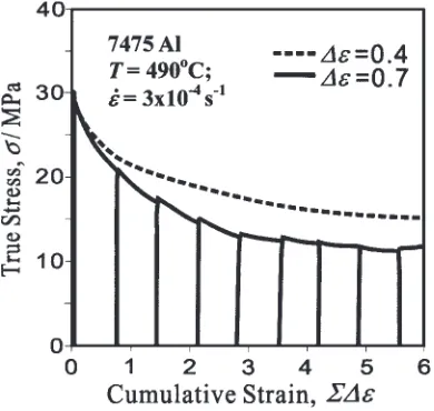
Figure 2 represents a series of true stress-true strain (-") curves plotted for 9 consecutive compression passes. The
envelope flow curve summarized for MDF of "¼0:4 is
also represented by a dashed line for comparison. It is seen that the integrated flow curve demonstrates a sharp stress peak just after yielding followed by significant work soften-ing. The latter takes place continuously up to strain of over
3.5 in"¼0:7and then the cumulative flow curve shows a
steady-state-like flow behavior. It is remarkable to see in
Fig. 2 that work softening appears more clearly in"¼0:7
and deformation stress reaches rapidly a steady state flow one
comparing with those during MDF of"¼0:4. The ratio of
the flow softening (¼p) and the stress peak (p),
=p, is around 0.6 in MDF of"¼0:7, while it is around
0.5 in MDF of"¼0:4. It can be seen in Fig. 2 that there is negligible small difference between the flow stresses
imme-diately before unloading and at reloading.16) This suggests
that any structural changes during interrupted test can be mainly affected by strain accumulation applied in each compression pass. In contrast, this difference was observed to be rather large in MDF of"¼0:4.14)
3.2 Microstructural development
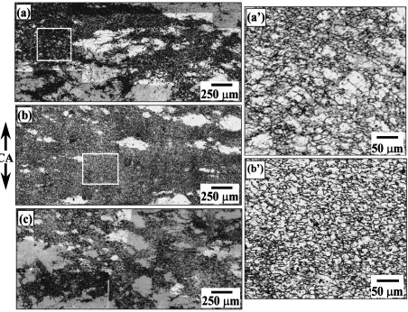
Typical microstructures evolved at various strains during
MDF of"¼0:7are represented in Fig. 3. The regions that
appear dark in color are composed of new fine grains with an
average size of around 7.5mm, as can be seen in Figs. 3(a’)
and (b’), the enlarged portions outlined in Figs. 3(a) and (b). It is clearly seen in Fig. 3(a) that at a cumulative strain of 2.1,
i.e. after a first full cycle of MDF of "¼0:7, grain
refinement takes place frequently and the fine-grained regions are evolved inhomogeneously accompanied with some remained original grains. Original grains are gradually replaced to fine grains with strain increasing. At a strain of 3.5 (Fig. 3(b)), such new grains are almost fully developed and the volume fraction of fine grains is about 0.85. It is also remarkable to note in Figs. 3(a’) and (b’) that more equiaxed
grains are developed after "¼3:5 compared with those at
"¼2:1. In contrast, the fraction of fine grains evolved at a similar strain is significantly smaller during MDF of
"¼0:4, as shown in Fig. 3(c). It approaches, however, a saturation value of 0.85 at a higher strain of about 6, which is similar to that in"¼0:7(see Fig. 7(a)).
3.3 OIM microstructures
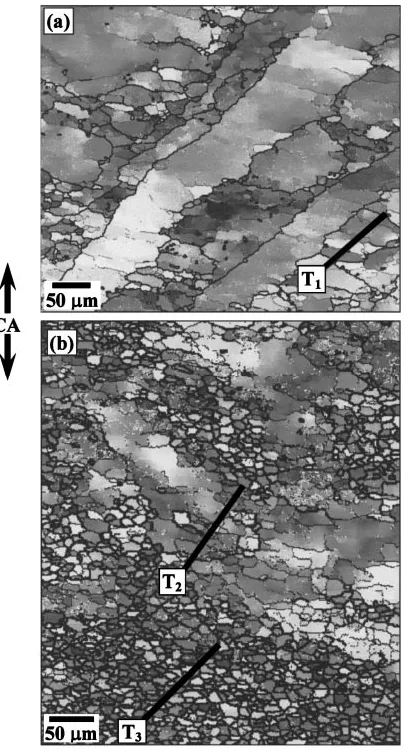
Figure 4 shows typical OIM pictures for the samples
processed with "¼0:7 to strains of (a) 0.7 and (b) 2.1.
Here the different grayscale levels indicate the different crystallographic orientations and the orientation differences
() between neighboring grid points, >2, >4 and
>15 are marked by thin white, narrow and bold black lines, respectively. It is seen in Fig. 4(a) that new boundaries with low to moderate and even high angle misorientations are developed within original grain interiors after a first compression. The crystal orientation is frequently changed in the regions fragmented by such boundaries (see Fig. 5). The latters may correspond to those of microshear or
deformation bands, as discussed in detail elsewhere.13,15) It
is also remarkable to see that several fine grains are evolved in the side of corrugated grain boundaries. After one cycle of
MDF to "¼2:1, several sets of deformation bands are
evolved in various directions, resulting in subdivision of original grains into separate misoriented domains, accom-panied with frequent evolution of new fine grains (Fig. 4(b)). With further straining, new grains with high-angle bounda-ries are rapidly and homogeneously developed not only in grain boundary regions, but also in grain interiors, although some rather coarser grains still remain in the regions of fine Fig. 1 Initial structure. IA is the ingot axis.
Fig. 2 Typical true stress-true strain (-") curve obtained during MDF of"¼0:7at 490C and at""_¼3104s1. The"curve in
MDF of"¼0:4is represented by dashed line for reference.
[image:2.595.72.267.563.748.2]grains (Fig. 3(b)). New deformation-induced boundaries were scarcely developed in such remained original grains, which existed stably even at a strain of 6.3.
Figure 5 represents the distribution of typical
point-to-point () and cumulative (point-to-origin) ()
misor-ientations developed in grain interiors along the lines T1, T2
and T3 indicated in Fig. 4. The value of defines the
relative difference in crystal orientation between two
adja-cent scan points with step of 1mm. In Fig. 5(a),does not
exceed generally 2-3except some spots with >10to
15, which corresponds to deformation-induced new
boun-daries. It is also remarkable to see that changes
discontinuously and crystal orientation is alternated at the same places. This suggests that highly heterogeneous deformation takes place in coarse grain interiors during hot deformation, leading to rigid local lattice rotation and then formation of dislocation subboundaries. These can be similar
to transition bands of microshear or kink bands.18–20) The
density and misorientation angle of such boundaries increase
with further repeated MDF to "¼2:1 (Figs. 5(b) and (c)).
New high angle boundaries with misorientations ranging
from 15 to beyond 50 are often developed in some grain
interiors, leading to almost full development of fine grains at high strains.
Figure 6 represents changes in the misorientation distri-butions of deformation-induced dislocation boundaries with
hot MDF. It is seen in Fig. 6(a) that most boundaries
developed at "¼0:7 exhibit low-to-medium angle
misor-ientations of below 20, although a small number of high
angle boundaries with over 40 is detected. With further
deformation, the fraction of low and moderate angle boundaries rapidly decreases and that of high-angle ones conversely increases in fine-grained regions. The misorien-tation distribution at high strains approaches the Mackenzie distribution of a fully annealed grain structure, as shown by dashed line in Fig. 6(d).21)
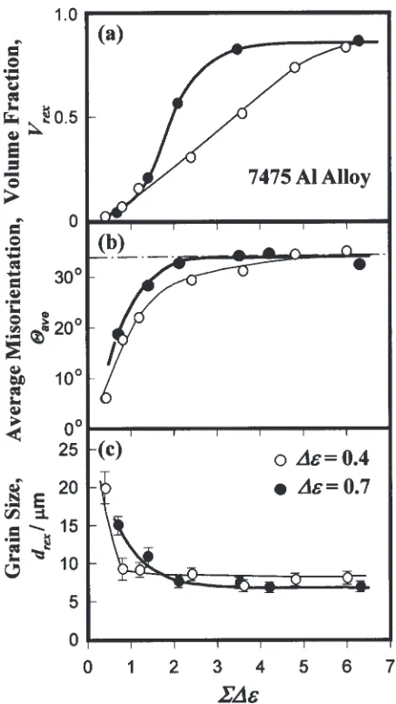
Figure 7 represents changes in several characteristic parameters of the microstructure developed with MDF of
"¼0:7. The data of "¼0:4 are included in Fig. 7 for
comparison. The volume fraction of new grains, Vrex, the
average misorientation,ave, in the fine-grained regions and
the average size of new grains, drex, are plotted against
accumulated strain in Figs. 7(a), 7(b) and 7(c), respectively.
Vrex increases with deformation and approaches a saturation
of about 0.85 at"3.aveincreases rapidly at low strains, gradually at moderate strains and then approaches a
saturation value of around 34 at"2. It is remarkable in
Figs. 7(a) and (b) that new grains are more rapidly formed in a low to moderate strain range with increase in pass strain from 0.4 to 0.7, that is, larger pass strain under MDF conditions can promote the occurrence of grain refinement.
On the other hand, drex rapidly drops at earlier stages of
Fig. 3 Microstructures developed in 7475 Al during MDF at 490C and at""_¼3104s1: (a), (a’)"¼2:1,"¼0:7; (b), (b’)
[image:3.595.74.526.71.417.2]deformation and approaches a roughly constant value after a cycle of MDF,i.e.at"¼1:2in MDF of"¼0:4and"¼ 2:1in MDF of"¼0:7(Fig. 7(c)). It should be noted in Fig. 7(c) thatdrex in"¼0:7 is smaller than that in "¼0:4.
The smaller grain size evolved in"¼0:7may result in a
lower flow stress (Fig. 2), as discussed in thenext Sectionsin
more details.
4. Discussion
4.1 Microstructural development during MDF
The present results mentioned above show that new grains are mainly developed during hot MDF due to grain fragmentation process accompanied by frequent evolution of deformation-induced subboundaries with low to moderate angle misorientation, which are recognized as the boundaries
of deformation and/or microshear bands. The authors13,15)
showed that during hot compression of the current alloy grain boundary sliding (GBS) takes place frequently and inhomo-geneously in the unsymmetric coarse-grained structure. GBS can occur with different rates along straight and corrugated segments of the original grain boundaries (see Fig. 1), resulting in formation of high strain gradients and stress
concentrations in grain interiors. For relaxation of the latters, microscopic shear bands can be developed in the columnar
grains even at early stages of hot deformation.13)
The same discussion can be applied to the structural
mechanism operating during MDF of both"¼0:4and 0.7.
It is possible to consider that deformation-induced bounda-ries such as microshear bands are developed parallel to each other during first compression (Fig. 4(a)). When uniaxial
compression is continuously applied to the material, i.e.
under a constant strain path condition, the misorientation of such boundaries is increased and their spacing is gradually reduced with compression, eventually leading to formation of
high-density two-dimensional planar microstructure, i.e.
layered lamellar structure.13) In contrast, changes in strain
path during repeated MDF can promote development of such boundaries in various directions. They are continuously formed by strain accumulation and microstructural hetero-geneities evolved in each compression pass, accompanying
with their intersection in grain interiors.13)Further MDF to
large strains results in progressive transformation of the crystallites fragmented by microshear bands into new grains. Fig. 4 Typical OIM pictures showing the microstructures developed in
7475 Al alloy during MDF at cumulative strains of (a) 0.7, and (b) 2.1. CA is the last compression axis.
Fig. 5 Typical point-to-point and point-to-origin misorientations devel-oped in original coarse grain interiors in 7475 Al alloy during MDF at T¼490C and""_¼3104s1. (a)"¼0:7, (b) and (c)"¼2:1.
Misorientations in (a), (b) and (c) were measured along the lines T1, T2
and T3indicated in Fig. 4, respectively.
[image:4.595.71.275.71.447.2] [image:4.595.320.531.73.453.2]This is considered to be a kind of continuous reactions sometimes called as continuous dynamic recrystallization
(cDRX).4,7,10–15,17,22) Various shearing directions appear
during MDF and so the number of repeated compression
passes can be more useful for evolution of equiaxed grains.13)
The stable grain size is, therefore, developed more rapidly
during MDF with smaller pass strain, i.e. "¼0:4 (Fig.
7(c)).
4.2 Effect of pass strain
The data in Figs. 3 and 7 indicate that fine grain formation during MDF can be dependent on not only total strain
accumulated, but also each pass strain, ". It has been
mentioned in Fig. 7 that increase in"from 0.4 to 0.7 under
[image:5.595.317.535.69.456.2]MDF conditions results in evolution of smaller stable grain size and also promotes more rapid increase in the volume fraction and average misorientation of new grains. Let us discuss here the effect of pass strain on such microstructural development in details.
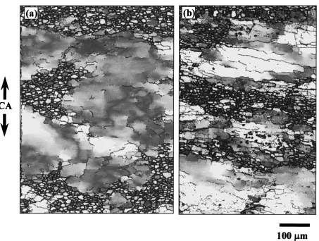
Figure 8 represents typical OIM microstructures developed in remained original grains at strains of around 2 during MDF of "¼0:4 and 0.7. The color and the thickness of boundaries have the same meanings as those in Fig. 4. It can be seen in Fig. 8 that the density of deformation-induced boundaries is much higher and the average size of new
evolved grains is smaller in MDF of"¼0:7compared with
those in MDF of "¼0:4. This suggests that, as larger
magnitude of local strains should be introduced during MDF of "¼0:7, the density and misorientation of dislocation subboundaries become larger, finally resulting in more rapid evolution of new finer grains. There may be several factors accelerating development of new grains during MDF with increasing".
(i). GBS.New grain evolution can be assisted by operation of GBS especially in the regions fragmented by microshear
bands, as discussed in 4.1. MDF with higher " can
introduce more frequently the boundaries with higher misorientation angles and then grain rotation may occur with higher rate in fragmented regions. This should addi-tionally accelerate transformation of low- to moderate angle boundaries to high angle ones e.g.13,15,17,23,24)This is one of the reasons why the volume fraction of fine grains is Fig. 6 Evolution of misorientation angle distribution of strain-induced
boundaries in fine-grained regions developed during MDF of"¼0:7. The broken line indicates the random misorientation distribution evaluated by Mackenzie.21)
[image:5.595.72.267.70.493.2]developed faster during MDF of"¼0:7(Figs. 3, 7 and 8).
(ii). Static restoration taking place between inter-pass.It
is known25)that a (sub)grain structure composed of higher
misoriented (sub)boundaries can be more stable compared with lower misoriented one and so may be less recovered during the period of inter-pass time in MDF. Interrupted flow
curves in "¼0:7 indicates that quite small softening
results from static recovery occurring at each deformation pass (Fig. 2). Such a static annealing effect, in contrast,
appeared rather large during interrupted test with
"¼0:4.14) This suggests that dislocation substructures evolved by previous deformation are more recovered under
MDF with smaller"and then new grains with high-angle
boundaries can be developed more slowly at moderate to high cumulative strains.
On the other hand, the characteristics of grain structures
developed during MDF (i.e.aveandVrex in Fig. 7) become
similar at severe large strains irrespective of ". It is
interesting to note that Vrex approaches a saturation value
below 1 even at high strains. Parts of relatively small original grains may remain stable because deformation accompanied by GBS takes place frequently in fine-grained regions. The volume fraction and size of remained original grains decrease and conversely the regions of new fine grains surrounding them increase with repeated MDF. Large strain gradients may, therefore, be hardly developed in these remaining
grains because of frequent operation of GBS and dynamic recovery in the adjacent fine-grained regions. Such a stable
grain structure is evolved at "3:5 during MDF of
"¼0:7, while it can be observed only at "6 during MDF of"¼0:4.
4.3 Flow softening during MDF
It is generally believed that main restoration mechanism operating during cDRX is principally dynamic recovery and so work softening can hardly take place during hot
deformation.11,12,22) The present data show, however, that
grain refinement taking place due to cDRX is accompanied with significant work softening at moderate to high strains, followed by apparent steady state in flow stresses and also in grain structure. When hot deformation is mainly controlled
by GBS, flow stress () depends on grain size (d) developed
under steady state flow conditions and vs d can be
represented by¼Cdk, where C, k>0.26)This suggests that
smaller d evolved can lead to lower . It is discussed in
detail14,15)that work softening can be resulted from frequent
operation of GBS in the fine-grained regions accompanied
with increase inVrex, which corresponds virtually to decrease
of the mean grain size in the whole microstructure.
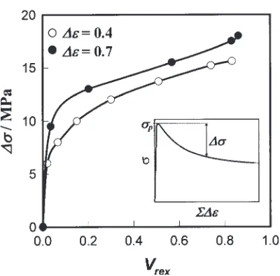
The quantitative dependencies between flow softening,
¼p, and microstructure development,Vrex, during
MDF of"¼0:4and 0.7 are shown in Fig. 9. Herepis the
Fig. 8 Typical OIM pictures showing the microstructures developed in remained original grains in 7475 Al alloy. (a)"¼2:4, "¼0:4and (b)"¼2:1,"¼0:7. The color and the thickness of lines have the same meaning as those in Fig. 4. CA is the last compression axis.
[image:6.595.75.528.66.408.2]peak stress andis the instantaneous flow stress in integrated
flow curves. It is seen thatincreases first rapidly, then at a
medium rate and finally at a lower constant rate with increasingVrex irrespective of". It is remarkable to see in
Fig. 9 that in "¼0:7 is always larger than that in
"¼0:4at an equivalentVrex. Such a larger softening taking
place in MDF of"¼0:7can result from smaller grain size
evolved (Fig. 7(c)). It is concluded, therefore, that more prominent flow softening appearing during MDF with larger pass strain can result from more rapid development of new grains with smaller size (Figs. 2 and 7).
5. Summary
The influence of pass strain (") in multidirectional
forging (MDF) was studied in a 7475Al alloy at a
temper-ature of 490C and at a strain rate of3104s1. The main
results obtained by MDF of "¼0:4 and 0.7 are
summa-rized as follows.
(1) The integrated flow curve exhibits a significant work softening at moderate strains, followed by steady-state
like flow at large strains. With increasing in ", flow
stress decreases more rapidly and approaches faster a lower steady-state flow stress.
(2) Deformation bands including microshear bands are developed in various directions during hot MDF and so intersect each other, resulting in continuous grain fragmentation. Further deformation leads to increase in the number and misorientation of these boundaries and finally almost full development of fine equiaxed grains in high strain. This grain refinement mechanism can be similar to continuous dynamic recrystallization.
(3) With increasing " from 0.4 to 0.7, higher density
deformation and/or microshear bands with larger misorientation angles are developed accompanied with evolution of finer grains at moderate strains and finally approach faster to a stable grain structure in high strain.
The characteristics of such strain-induced grains, i.e.
the average misorientation and the volume fraction, however, become almost the same at severe large strains irrespective of".
Acknowledgements
The authors acknowledge with gratitude the financial support received from the Light Metals Education Founda-tion in Japan. O.S. thanks the Japan Society for the PromoFounda-tion Science for providing a scientific fellowship. A.G. wishes to thank the Japanese Government for providing the scholar-ship.
REFERENCES
1) R. Z. Valiev, R. K. Islamgaliev and I. V. Alexandrov: Progr. Mater. Sci. 45(2000) 103–189.
2) Y. Iwahashi, Z. Horita, M. Nemoto and T. G. Langdon: Acta. Mater.45 (1997) 4733–4741.
3) K. Nakashima, Z. Horita, M. Nemoto and T. G. Langdon: Acta. Mater. 46(1998) 1589–1599.
4) F. J. Humphreys, P. B. Prangnell, J. R. Bowen, A. Gholinia and C. Harris: Phil. Trans. R. Soc. Lond.A357(1999) 1663–1680. 5) J. R. Bowen, P. B. Prangnell and F. J. Humphreys: Mater. Sci. Tech.16
(2000) 1246–1250.
6) A. Gholinia, P. B. Prangnell and M. V. Markushev: Acta. Mater.48 (2000) 1115–1130.
7) O. Sitdikov, R. Kaibyshev, I. Safarov and I. Mazurina: Phys. Met. Metallogr.92(2001) 270–280.
8) M. Furukawa, Z. Horita, M. Nemoto and T. G. Langdon: Mater. Sci. Eng.A324(2002) 82–89.
9) R. M. Imayev, G. A. Salishchev, O. N. Senkov, V. M. Imayev, M. R. Shagiev, N. K. Gabdullin, A. V. Kuznetsov and F. H. Froes: Mater. Sci. Eng.A300(2001) 263–277.
10) A. Belyakov, W. Gao, H. Miura and T. Sakai: Metal. Mater. Trans.29A (1998) 2957–2965.
11) A. Belyakov, T. Sakai, H. Miura and R. Kaibyshev: ISIJ Int.39(1999) 592–599.
12) A. Belyakov, T. Sakai, H. Miura and K.Tsuzaki: Philos. Mag.A81 (2001) 2629–2643.
13) O. Sitdikov, T. Sakai, A. Goloborodko and H. Miura: Scr. Meter.51 (2004) 175–179.
14) O. Sitdikov, A. Goloborodko, T. Sakai, H. Miura and R. Kaibyshev: Mater. Sci. For.426–432(2003) 381–386.
15) R. Kaibyshev, O. Sitdikov, A. Goloborodko and T. Sakai: Mater. Sci. Eng.A344(2003) 348–356.
16) It can be seen in Fig. 2 that the flow stresses after reloading are sometimes a little higher than those just before unloading. This may be resulted from increase in the resistance of dislocation motion dragging a solute atmosphere.17) However, such a dragging effect can be negligible small comparing with the stress level, as it has been discussed before.15,17)
17) T. Sakai and C. Takahashi: Mater. Trans., JIM32(1991) 375–382. 18) B. Bay, N. Hansen, D. A. Hughes and D. Kuhlmann-Wilsdorf: Acta.
Metall. Mater.40(1992) 205–219.
19) P. J. Hurley and F. J. Humphreys: Acta. Mater.51(2003) 1087–1102. 20) X. Yang, H. Miura and T. Sakai: Mater. Trans.44(2003) 197–203. 21) J. K. Mackenzie: Biometrika45(1958) 229–240.
22) F. J. Humphreys and M. Hatherly: Recrystallization and Related Annealing Phenomena, (Pergamon, 1995) p. 497.
23) J. Liu and D. J. Chakrabarti: Acta. Mater.44(1996) 4647–4661. 24) X. Yang, H. Miura and T. Sakai: Mater. Trans.43(2002) 2400–2407. 25) F. J. Humphreys: Acta. Mater.45(1997) 4231–4240.
26) T. G. Nieh, J. Wadsworth and O. D. Sherby:Superplasticity in Metals and Ceramics, (Univ. Press, 1997) p. 273.
[image:7.595.69.269.66.263.2]