In conjunction with the prepared launching of the IPPC (Integrated Pollution Prevention and Control) Law (ANONYMOUS 1999) it is necessary to reduce, in all branches of the human activity and thus also in ag-riculture, material and electric power consumption and to apply environment-friendly technological procedures. The measurements carried out at our workplace (FRYČ
2001) proved that the air flow through the milking ma-chine vacuum pump markedly exceeded the average
consumption of the milking machine. The efficiency of the vacuum pump is namely based on the maximum permissible air consumption by the milking machine to which moreover a reserve of the vacuum pump ef-ficiency is added being comparable with the consump-tion of the milking machine. With respect to these facts we endeavoured to find whether the vacuum pump run could be controlled, which would result in a reduction of electric power.
The paper came into existence within Research Project No. MSM 7321 00001 of the Ministry of Education, Youth and Sports of the Czech Republic.
Comparison of the operation of milking machine control
valves and a newly designed regulating device
J. F
RYČMendel University of Agriculture and Forestry, Brno, Czech Republic
ABSTRACT: One of the basic demands for milking machines is to maintain a constant vacuum level if air consumption by milking machine is changed. The author designed a device with reducing valve for vacuum level regulation and a simultaneous vacuum pump control enabling electric power to be reduced. The paper deals with a comparison of the operation of standard control valves with the newly designed device used for vacuum regulation from the viewpoint of dynamic properties. When measuring vacuum stability by applying various regulation methods and a subsequent statistical evaluation of the results obtained it was proven that the function of the newly designed regulating device was comparable with the best reducing valves used so far.
Keywords: milking machine; vacuum control; control valve; vacuum stability
3 5 9
8
4
6 7
1 2
~ 220 V ~ 380 V
vacuum scanning electric wiring
[image:1.595.74.503.429.677.2]vacuum pipeline vacuum scanning electric wiring vacuum pipeline
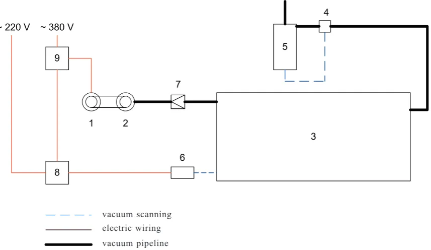
Fig. 1. Control unit with pressure-reducing valve – Functional diagram
110 RES. AGR. ENG., 49, 2003 (3): 110–114 RES. AGR. ENG., 49, 2003 (3): 110–114 111 MATERIAL AND METHOD
If a constant vacuum is to be obtained by applying a standard regulation method of vacuum magnitude, the control valve must suck so much atmospheric air into the vacuum system that the sum of the air amount sucked in by the milking machine and the control valve within a time interval is constant. The vacuum pump works at a full efficiency irrespective of the actual consumption by the milking machine. For this reason a device for vacuum regulation was designed which does not suck any atmospheric air. Only the air from the milking machine passes through the vacuum pump, its run depending on the instantaneous air consumption. The device is designed to control vacuum pump run by a frequency converter. To verify theoretical presup-positions and the function of the regulating device with reducing valve vacuum pump electric motor switching on and off was first used. Device principle is illustrated in Fig. 1. Vacuum pump set is directly connected to a large capacity air chamber (hereinafter designated as a “big air chamber”). Connecting piping between the vacuum pump and the big air chamber is provided with a non-return valve so that no vacuum pump reverse run takes place by the effect of big air chamber vacuum resulting in undesirable air sucking. In the big air chamber an vacuum within the chosen range of pn1up to pn2 (pn1 > pn2) is maintained,its minimum value (pn2) being higher than the working vacuum of the milking machine (pnp). Basic device parameters were specified by the author (FRYČ 2002).
Device function was very satisfactory at a steady-state regime (FRYČ, KUKLA 2002). It was necessary to test device operation at dynamic changes which can occur during milking. With respect to a different principle in the function of regulating device with reducing valve no diagnostic measurements in accordance with the Stand-ard ISO 6690 could be carried out. For this reason vacu-um stability was measured being not compulsory based on the Standard ISO 6690 in force, however, its previous versions involved the measurement and recommended it for a comparison of different regulation methods. Meas-urements by applying the newly suggested regulation method were made and for a comparison also a standard measurement of vacuum regulation with weight control valve and a diaphragm control servo-valve was carried out. The measurements proceeded both in laboratory conditions and on the milking machine at a stable. In ei-ther case adapted pipe-type milking machines ZD 2-020 manufactured by Agrostroj Pelhřimov and connected based on the diagram in Fig. 2 were used. The labora-tory milking machine was of the following parameters: milking piping up to collecting vessel was 24 m long, total air piping length up to vacuum pump being 27 m. Vacuum pump efficiency was 7.8 dm3/s. Losses cau-sed by milking and air piping leakages measured in accordance with the Standard ISO 6690 amounted to 0.3 dm3/s.
The measurements were carried out at the recon-structed cowshed K 174 of the agricultural enterprise GenAgro Ostrovačice Říčany, the cowshed being a six-row, through stable with three independent
milk-3 5 9
8
4
6 7
1 2
~ 380 V
vacuum scanning electirc wiring vacuum pipeline
~ 220 V
b A3
Vp a
11 c
12 13
14
e
f
Vr A2 h
g
15 16
19 17 18 d
A1 Vm
[image:2.595.74.510.53.284.2]10
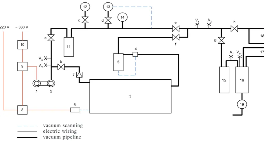
Fig. 2. Laboratory measurement installation – Functional diagram
1 – electric motor; 2 – vacuum pump; 3 – big air chamber; 4 – pressure-reducing valve; 5 – small air chamber; 6 – pressure trans-ducer; 7 – back-pressure valve; 8 – control unit; 9 – electric motor control; 10 – electrometer; 11 – air chamber; 12 – control valve with weight; 13 – diaphragm control servo-valve; 14 – vacuum gauge; 15 – sanitary trap; 16 – receiver; 17 – milk pipeline; 18 – air pipeline; 19 – milk pump
a – h – cocks; A – air flow rate measuring points; V – vacuum measuring points vacuum scanning
ing machines, model ZD 2-020. For experiments the milking machine of the best technical condition was chosen (the highest vacuum pump efficiency and the lowest losses by leakages). Milking piping length up to collecting vessel was 122 m, total air piping length up to vacuum pumps being 154 m. The efficiency of both vacuum pumps totalled 19.0 dm3/s. Losses caused by milking and air piping leakage were 2.5 dm3/s based on the Standard ISO 6690.
The measurements were carried out as follows: 1. The milking machine was put into operation in the
following way: vacuum pump was switched on and all milking units intended for milking were connected to the milking machine. Portable milking units were located in the most distant place. Teat-cups were closed by stoppers and all checking devices set for milking. All additional devices making use of vacuum were connected including those being inactive during milking.
2. The vacuum pump was allowed to run for at least 15 minutes prior to measuring.
3. The value of the atmospheric pressure and milking machine working vacuum was recorded.
4. Adjustment of cocks for individual measurements was made as follows (Fig. 2):
Measuring the control valve with weight: cocks a, c, e – opened; cocks b, d, f – closed. Measuring the dia-phragm control servo-valve: cocks a, d, e – opened; cocks b, c, f – closed. Measuring the regulating de-vice with reducing valve: cocks b, f – opened; cocks a, e – closed.
5. The milking hose of the most distant milking unit was throttled, disconnected and connected to the ves-sel with atmospheric pressure. The capacity of this vessel was large enough to hold 10 l of air from the milking machine after releasing milking hose throttle – measured at atmospheric pressure.
6. A device intended for vacuum recording was con-nected to the adjacent milking unit by means of a T-piece in a short milking hose.
7. Device for vacuum recording was put into opera-tion and the milking hose throttling was quickly opened.
8. Maximum value of vacuum drop in kPa and the time in seconds within which the vacuum returned to its initial value were read and both quantities multiplied between each other.
In dependence on the atmospheric pressure and the value of working vacuum set the vessel capacity based on Item 5 was determined. Air amount V10 sucked into the vacuum system of the milking machine is based on the difference between the vessel capacity VN and the air volume VZ remaining in the vessel after generating nominal vacuum pn converted to atmospheric pressure pa and is expressed by the relation:
V10 = VN – VZ (m3) (1)
while VZ can be expressed by the relation:
pa – pn
VZ = VN ––––––– (m3) (2)
pa
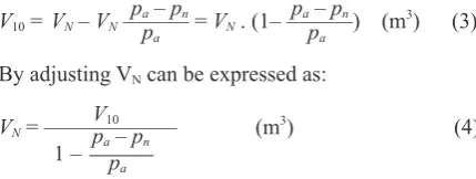
and after substituting into the relation (1) V10 can be adjusted as follows:
pa – pn pa – pn
V10 = VN – VN –––––– = VN . (1– ––––––) (m3) (3) pa pa
By adjusting VN can be expressed as: V
10
VN = –––––––––––– (m3) (4)
1 – pa – pn pa
Laboratory measurements were carried out at the at-mospheric pressure of 99.0 kPa. In dependence on the atmospheric pressure the capacity of the closed vessel intended for a single air inlet of 10 dm3 was computed based on the relation (4) as follows:
V10 10
VN = ––––––––– = –––––––––– = 19.8 dm3 (5) 1 – pa – pn 1 – 99 – 50
pa 99
Cowshed measurements were made at the atmos-pheric pressure of 101.5 kPa. Closed vessel capacity was calculated based on the relation (4) as follows:
V10 10
VN = ––––––––– = –––––––––––– = 20.3 dm3 (6) 1 – pa – pn 1 – 101.5 – 50
pa 101.5
Milk can with cover was used as closed vessel. The can was fully filled with water and by means of a gradu-ated vessel its capacity measured. Prior to the measure-ment the can was filled with a specified amount of water so that the air volume in the can exactly corresponded to the capacity computed. Vacuum drop (magnitude) and the time of its duration were recorded by means of the instrument Pulsator tester PT IV operating based on the method of Item 2. Then the maximum value of vacuum drop in kPa was subtracted together with the time in seconds within which the vacuum returned to its initial value and both quantities were multiplied between each other.
RESULTS AND DISCUSSION
In accordance with the Standard ISO 5707 the pro-duct of the vacuum drop in kPa and the time in seconds within which the vacuum returns to its initial value shall not exceed 20 kPa/s. The results of the laboratory measurements are listed in Table 1. The best result, i.e. the lowest average value (7.1 kPa/s) was obtained when using a diaphragm control servo-valve. Regulating devi-ce with reducing valve revealed slightly worse parame-ters (9.3 kPa/s). The worst results of an average value of 18.2 kPa/s approaching the permissible maximum were obtained when using a weight control valve.
[image:3.595.314.529.123.204.2]112 RES. AGR. ENG., 49, 2003 (3): 110–114 RES. AGR. ENG., 49, 2003 (3): 110–114 113 control servo-valve. Regulating device with reducing
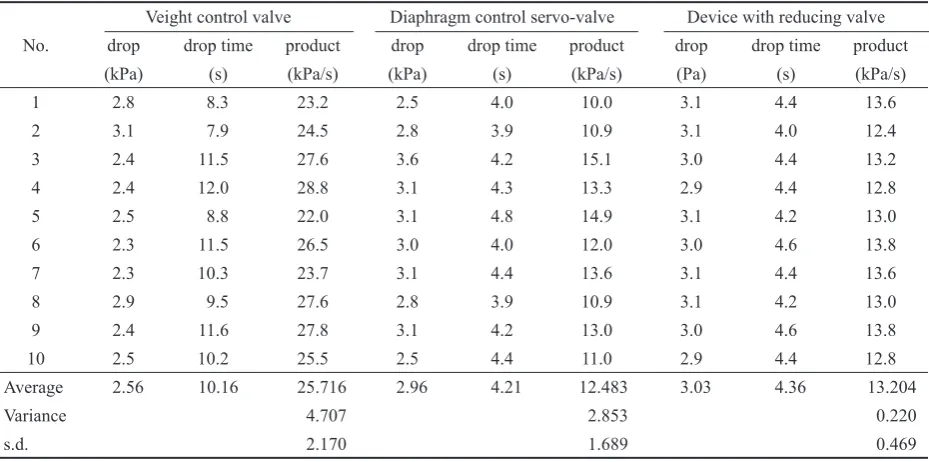
valve revealed a little worse parameters (13.2 kPa/s). The worst results of an average value of 25.7 kPa/s were found when using a weight control valve. The milking machine provided with this control valve does not com-ply with the value specified.
CONCLUSION
Both in laboratory and stable measurements the dif-ferences in the values between the diaphragm control servo-valve and the regulating device with reducing valve were statistically insignificant. The differences in the values between the weight control valve and the
di-aphragm control servo-valve are statistically significant. Also the differences in the values between the weight control valve and the regulating device with reducing valve are statistically significant. Based on the measure-ments made and their evaluation it can be stated that the newly designed regulating device with reducing valve is comparable with the present control servo-valves from the viewpoint of the dynamic properties.
References
[image:4.595.62.538.68.300.2]Standard ISO 5707 1983 Milking machine installations – Con-struction and performance. Switzerland,International Orga-nization for Standardization: 14.
Table 1. Measured and computed values of vacuum stability found at laboratory
Veight control valve Diaphragm control servo-valve Device with reducing valve
No. drop drop time product drop drop time product drop drop time product
(kPa) (s) (kPa/s) (kPa) (s) (kPa/s) (kPa) (s) (kPa/s)
1 3.8 4.9 18.6 3.8 1.8 6.8 3.8 3.1 11.8
2 3.8 4.9 18.6 4.6 2.2 10.1 3.8 2.6 9.9
3 3.8 4.9 18.6 3.8 2.0 7.6 3.8 2.6 9.9
4 3.8 4.4 16.7 3.1 2.2 6.8 3.1 2.6 8.1
5 3.8 4.9 18.6 3.1 1.8 5.6 3.8 3.1 11.8
6 3.8 4.9 18.6 3.0 1.8 5.4 3.8 2.2 8.4
7 3.8 4.9 18.6 3.1 2.2 6.8 3.1 2.6 8.1
8 3.8 4.9 18.6 3.8 2.2 8.4 3.1 2.2 6.8
9 3.8 4.4 16.7 3.1 2.2 6.8 3.8 2.2 8.4
10 4.1 4.4 18.0 3.8 1.8 6.8 3.8 2.6 9.9
Average 3.83 4.75 18.182 3.52 2.02 7.120 3.59 2.58 9.286
Variance 0.564 1.652 2.430
s.d. 0.751 1.285 1.559
s.d – standard deviation
Table 2. Measured and computed values of vacuum stability found at stable
Veight control valve Diaphragm control servo-valve Device with reducing valve
No. drop drop time product drop drop time product drop drop time product
(kPa) (s) (kPa/s) (kPa) (s) (kPa/s) (Pa) (s) (kPa/s)
1 2.8 8.3 23.2 2.5 4.0 10.0 3.1 4.4 13.6
2 3.1 7.9 24.5 2.8 3.9 10.9 3.1 4.0 12.4
3 2.4 11.5 27.6 3.6 4.2 15.1 3.0 4.4 13.2
4 2.4 12.0 28.8 3.1 4.3 13.3 2.9 4.4 12.8
5 2.5 8.8 22.0 3.1 4.8 14.9 3.1 4.2 13.0
6 2.3 11.5 26.5 3.0 4.0 12.0 3.0 4.6 13.8
7 2.3 10.3 23.7 3.1 4.4 13.6 3.1 4.4 13.6
8 2.9 9.5 27.6 2.8 3.9 10.9 3.1 4.2 13.0
9 2.4 11.6 27.8 3.1 4.2 13.0 3.0 4.6 13.8
10 2.5 10.2 25.5 2.5 4.4 11.0 2.9 4.4 12.8
Average 2.56 10.16 25.716 2.96 4.21 12.483 3.03 4.36 13.204
Variance 4.707 2.853 0.220
[image:4.595.66.531.347.578.2]Standard ISO 6690 1983 Milking machine installations – Me-chanical tests. Switzerland,International Organization for Standardization: 6.
ANONYMOUS, 1999. Příručka ke směrnici Rady 96/61/EC (IPPC). Praha, MŽP ČR.
FRYČ J., 2001. Stanovení dynamiky proudění vzduchu v pod-tlakovém systému pro možnost řízení chodu vývěvy. Acta Mechanica Slovaca, 5: 111–114.
FRYČ J., 2002. Regulation of vacuum in milking machines by unit with pressure reducing valve and assessment of its basic parameters. Res. Agr. Eng., 48: 7–11.
FRYČ J., KUKLA R., 2002. Určení parametrů zařízení pro regulaci podtlaku s redukčním ventilem. In: Technika v pro-cesech trvale udržitelného hospodaření a produkce bezpečných potravin. Brno, MZLU: 300–303.
Received for publication May 29, 2003 Accepted after corrections July 14, 2003
Porovnání činností regulačních ventilů dojicích strojů a navrženého regulačního
zařízení
ABSTRAKT: Jedním ze základních požadavků na dojicí stroje je udržování konstantní úrovně podtlaku při změnách spotřeby vzduchu dojicím strojem. Autor příspěvku navrhl zařízení pro regulaci úrovně podtlaku s redukčním ventilem při současném řízení chodu vývěvy, což umožňuje snížit spotřebu elektrické energie. Příspěvek se zabývá porovnáním činnosti běžně používaných regulačních ventilů s navrženým zařízením pro regulaci podtlaku z hlediska dynamických vlastností. Jak při měření v laboratoři, tak i při měření ve stáji bylo zjištěno, že rozdíl hodnot mezi membránovým regulačním servoventilem a regulačním zařízením s redukčním ventilem není statisticky významný. Rozdíly hodnot mezi závažovým regulačním ventilem a membránovým regu-lačním servoventilem nebo mezi závažovým reguregu-lačním ventilem a reguregu-lačním zařízením s redukčním ventilem jsou statisticky významné. Na základě provedených měření a jejich vyhodnocení lze tvrdit, že navržené regulační zařízení s redukčním ventilem je z hlediska dynamických vlastností srovnatelné se současnými regulačními servoventily.
Klíčová slova: dojicí stroj; regulace podtlaku; regulační ventil; stabilita podtlaku
Corresponding author:
Ing. JIŘÍ FRYČ, CSc., Mendelova zemědělská a lesnická univerzita, Agronomická fakulta, Zemědělská 1, 613 00 Brno, Česká republika