DTMF CONTROLLED ROBOT USING ARDUINO
Sushma Ronanki
1, Divya Tandra
2, Prasanth Pogiri
3, Dilleswara Rao T
41
Assistant Professor,
2,3,4Student, B.Tech, M.Tech, Electronics and Communication,
SSCE, Srikakulam, Andhra Pradesh (India)
ABSTRACT
In this paper, we can control the Robot using Dual Tone Multi Frequency (DTMF) technology. DTMF
technology is most useful technique at present days. It is worked on to methods digital signal processing (DSP).
Wireless-control of robots uses RF circuit that has the drawbacks of limited working range and limited control.
This DTMF is gives advantage over the RF; it increases the range of working and also gives good results in
case of motion and direction of robot using mobile phone through micro controller. This type of wireless
communication gives the remote handling operation of Robot using DTMF.
Keywords: Atmega328p microcontroller, DTMF, Mobile module, Motor drive IC, motor.
I. INTRODUCTION
380 | P a g e
II.BLOCK DIAGRAM OF DTMF CONTROLLED ROBOT
Figure 1: block diagram of DTMF controlled robot using Arduino
II HARDWARE DESCRIPTION
3.1DTMF DECODER
DTMF means Dual-Tone-Multi-Frequency. DTMF signaling is used for telecommunication signaling over analog telephone lines in the voice-frequency band between telephone handsets and other communication devices and the switching centre. The DTMF system generally uses eight different frequency signals transmitted in pairs to represent sixteen different numbers, symbols and letters. When someone presses any key in the key pad of the handset, a DTMF signal is generate unique tone which consists of two different frequencies one each of higher frequency range (>1KHz) and lower frequency (<1KHz) range. The resultant tone is convolution of two frequencies.The frequencies and their corresponding frequency are shown in Table 3.1. Each of these tones is composed of two pure sine waves of the low and high frequencies superimposed on each other. These two frequencies explicitly represent one of the digits on the telephone keypad.
Thus generated signal can be expressed mathematically as follows: (1) Where:
Table 1: DTMF Keypad Frequency
Each key has a specific Tone frequency. For example if the "5" key is pressed then generated frequency tone is 770 + 1336 = 2106 Hz. The key "1" is pressed then frequency of 697 + 1209 = 1906 Hz which is shown in below figure.
Figure 2: Two Pure Sine Waves combine for form the DTMF Tone for "1"
3.2
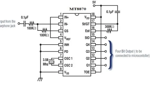
CM8870 DTMF DDECODER IC
Figure 3: MT-8870 DTMF Decoder Configuration
382 | P a g e decode all 16 DTMF tone pairs into a 4-bit code. The DTMF signal from the user mobile phone is picked up by the system mobile phone. The tip and ring of the microphone is connected to the specified pin of CM8870 as shown in the Fig. 4. C1, R1 and R2 have been adjusted for gain control of the input signal. Resistance R3 and capacitor C2 has been used to set the "guard time ‟ which is a time duration through which a valid DTMF tone must be present for its recognition. The "Q-test ‟ signal (pin15) indicates that the valid DTMF tone has been detected. Increase the resistor between pin2 and pin3 (not the one connects to 100nF) from 100K to 220k, 330K or 470K. This increases the input gain from 1 to 2.2, 3.3 or 4.7 to suit your input signal strength.
3.3 ATMEGA328P MICROCONTROLLER
ATmega328P is a 32K 8-bit microcontroller based on AVR architecture. ATmega328P is commonly used in many projects and autonomous systems where a simple, low powered, low-cost micro-controller is needed. It has 14 digital input/output pins (out of which 6 can be exploited as PWM outputs), 6 analog input, 16 MHz crystal oscillator.
The high-performance Atmel AVR RISC-based microcontroller combines 32KB ISP flash memory with read-while-write capabilities, 1KB EEPROM, 2KB SRAM, 23 general purpose I/O lines, 32 general purpose working registers, three flexible timer/counters with compare modes, internal and external interrupts, serial programmable USART, a byte-oriented 2-wire serial interface, SPI serial port, 6-channel 10-bit A/D converter (8-channels in TQFP and QFN/MLF packages), programmable watchdog timer with internal oscillator, and five software selectable power saving modes. The device operates between 1.8-5.5 volts
.
Figure 4: Pin Diagram of Atmega328P
3.4 DC MOTOR DRIVE
Figure 5: working of motor Figure 6: L293D IC
3.4.1 WORKING OF L293D
The 4 input pins for this L293D, pin 2,7 on the left and pin 15 ,10 on the right as shown on the pin diagram. Left input pins will regulate the rotation of motor connected across left side and right input for motor on the right hand side. The motors are rotated on the basis of the inputs provided across the input pins as LOGIC 0 or LOGIC 1.
3.4.2 L293D LOGIC TABLE
Pin 1 Enable Pin 2 Pin 7 Function
HIGH HIGH LOW Anticlockwise HIGH LOW HIGH Clockwise HIGH HIGH HIGH No Rotation HIGH LOW LOW No Rotation
LOW X X No Rotation
Table 2: L293D Logic Table
3.5 OPERATION OF THE CIRCUIT
384 | P a g e
3.6 DTMF TONE DECODING ALGORITHM
Table 3: DTMF tone decoding algorithm
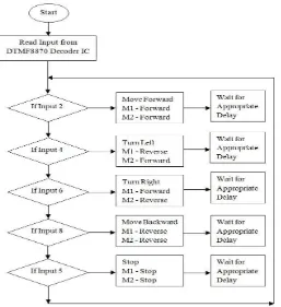
IV. OPERATIONAL FLOWCHART OF THE SYSTEM
Figure 7: Operational flowchart of the system
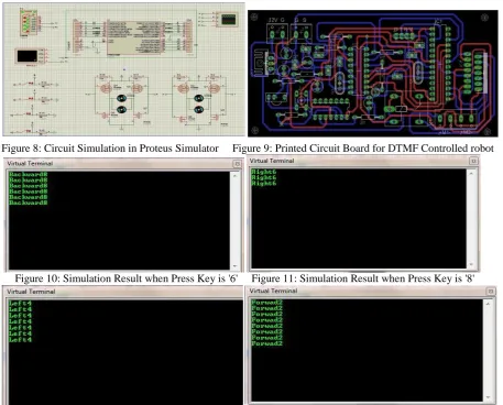
V. CIRCUIT SIMULATION
The Simulation of the circuit is shown in figure 6. Atmega328P Microcontroller has been used in simulation. Four DC Motor are connected to Port B (Pin 2,3,4,5) of Microcontroller through H-Bridge driver Circuit.
Low Frequency Group
High
Frequency Group Digit O E D 3 D 2 D 1 D 0
697 1209 1 H 0 0 0 1
697 1336 2 H 0 0 1 0
697 1477 3 H 0 0 1 1
770 1209 4 H 0 1 0 0
770 1336 5 H 0 1 0 1
770 1477 6 H 0 1 1 0
852 1209 7 H 0 1 1 1
852 1336 8 H 1 0 0 0
852 1477 9 H 1 0 0 1
941 1209 * H 1 0 1 0
941 1336 0 H 1 0 1 1
Figure 8: Circuit Simulation in Proteus Simulator Figure 9: Printed Circuit Board for DTMF Controlled robot
Figure 10: Simulation Result when Press Key is '6' Figure 11: Simulation Result when Press Key is '8'
Figure 12: Simulation Result when Press Key is '4' Figure 13: Simulation Result when Press Key is '2'
VI. RESULT
Figure 14: Designed Robot
VII. CONCLUSION
386 | P a g e advantages of robust control, working range as large as the coverage area of the service provider, no interference with other controllers and up to twelve controls. Although the appearance and capabilities of robots vary vastly, all robots share the features of a mechanical, movable structure under some form of control.
REFERENCES
[1] Awab Fakih, Jovita Serrao, “Cell Phone Operated Robotic Car.” International Journal of Scientific & Engineering Research, ISSN 2229-5518.
[2] Yun Chan Cho and Jae Wook Jeon “Remote Robot control System based on DTMF of Mobile Phone”, IEEE International Conference INDIN 2008, July 2008.
[3] http://www.dialabc.com/sound/dtmf.html
[4] http://www.robotplatform.com/howto/L293/motor_driver_1.html [5] http://www.atmel.in/devices/ATMEGA328.aspx