625 | P a g e
STRESS -STRAIN ANALYSIS AND EXPERIMENTAL
VERIFICATION OF THREE-ROLL PYRAMIDAL
SHAPE CONFIGURATION ROLL BENDING
MACHINE
Mr. Pramod R. Walunj
1, B. Prof. Dr. A. D. Desai
2,
C. Prof. A. B. Verma
31,2,3
Department of Mechanical Engineering,
Shree Ramchandra College of engineering Lonikand, Pune
ABSTRACT
Three Roll bending is an efficient metal forming technique, where plates are bent to a desired curvature using
forming rolls. Three rolling sheet forming process is one of the most widely used techniques for manufacturing
asymmetric hollow shapes, basic component of cylindrical vessels and structures used for different engineering
applications. Three-roll pyramidal roll bending process is beginning to be taken into serious consideration by
industries for producing big, thick parts such as the conically shaped crown of a Francis turbine runner and of
a wind turbine tower. It is important to bend the sheet smoothly and safely, without cracks and working for
longer life. While bending the sheet metal, stress and strain is developed in the sheet. It is highly essential that
the stress and strain are within the limits of the material properties such as mild steel and the factor of safety
desired by the engineering applications. Also, there must be maximum displacement of top roller allowed
without endangering crack formation in work piece obtained.
Three-roll pyramidal roll bending process primarily deals with calculating the relation of the top roller
positions and the stress and strain developed during displacement of top roller for different thickness of the
sheet metal. In this study three dimensional dynamic Finite Element (FE) model of a pyramidal three roller
bending process is developed using the ANSYS software.
The simulation results are compared with experiments performed with three roll bending machine. Maximum
displacement of top roller allowed without endangering crack formation in work piece is observed as 12 mm
from FEA results. From FEA and practical results comparison strain values are in conformance with each other
with maximum variation of 10.6 % which validates the FEA results. The limit for maximum displacement of top
roller is 12 mm, within which the von mises stress is less than the stress value of material of construction i.e.
mild steel of the roller.
I.
I
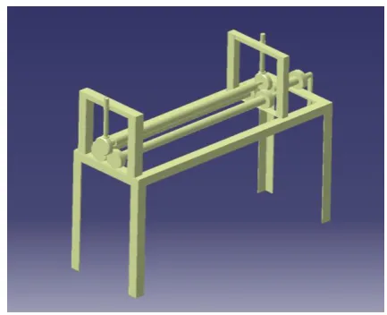
NTRODUCTIONThree roller bending machines are widely used in heavy engineering applications for the manufacturing of skeleton of the construction of tunnels, cylindrical tanks, shell of boiler and heat exchangers, fuel tanks for launch vehicles in space applications, pressure vessels, tall towers, reactors, etc. Top roller the load required to bend the sheet is the function of various parameters viz. plate thickness, width, shell diameter to be rolled, plate material property and gap between the bottom rollers etc. Machine capacity is limited by size and shape of motor of three roll bending machine motor. It consists of two bottom rollers and a one top roller as shown in Fig.1. Sheet metal plates with specified contours are rolled without decrease in thickness to get the desired cylindrical shape. The plate undergoes plastic deformation and it is cold forming process and hence it has higher dimensional accuracy. The various machine elements used in the construction three roll bending machine are as shaft, bearings, gear, lead screw, lever and frame.
Three roller pyramidal bending process has four stages as described under, (a) static bending (b) forward rolling
(c) backward rolling and (d) unloading of the work piece.
Fig.1. Three roll pyramidal bending machine.
In the first stage the metal sheet is kept between top roller and bottom rollers and the top roller is given vertical displacement to get the required bending. In next stage the bottom rollers are driven using motors or by hand lever in forward direction to get the roll bending of the plate. Similarly the rollers are driven in backward direction to get better dimensional accuracy of the final shape. The bent sheet is then unloaded by raising the top roller. The process is performed using many materials such like carbon and alloy steels, aluminium alloys. Rolling bending machines with three rolls are indispensible to the production of cylindrical shapes with different radiuses of curvatures without endangering crack formation in work piece.
II.
LITERATURE
REVIEW
627 | P a g e sections and shells are produced using three roller conical bending machine. M. K. Chudasama and H. K. Raval (2013) [2], they fomalated an analytical model is developed to predict bending force which will be acting during three roller conical bending process. Analytical results and experimental results were compared. Force predicted by analytical model is in close proximity of the experimental results. The error in the prediction was ±10%. Hence the model gives quite satisfactory results. Zen Zemin Fu et al (2013) [3], ] in which they stated that the three-roll bending forming of sheet metal is an important and flexible manufacturing process due to simple configuration. and explain the process through macroscopic metal deformation. An analytical model and ABAQUS finite element model (FEM) are proposed Then, the three-roll bending forming process of a semi-circle-shaped work piece with 3,105 mm (length) × 714 mm (width) × 545 mm (height) is simulated with FEM established by the optimum tool and process parameters. A. H. Gandhi et al ( 2008) [5], .described the work proposed an analytical and empirical model to estimate the top roller position explicitly as a function of desired radius of curvature for three-roller cylindrical bending of plates, considering the contact point shift at the bottom roller plate interfaces. Effect of initial strain and change of material properties during deformation is neglected. Top roller positions for loaded radius of curvature are plotted for a certain set of data for centre distance between bottom rollers and bottom roller radius. From above literature it is fond that we can bend a sheet metal of required shape by changing the roller position of top and lateral rollers.
III. FINITE ELEMENT ANALYSIS
A. Results of conventional steel shaft
Three dimensional solid models for the three roller bending machine assembly is modeled using CATIA V5. Fig.2. shows the assembly of three roll pyramidal bending machine.
Fig. 2. CAD model for Propeller Shaft Assembly.
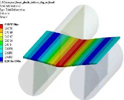
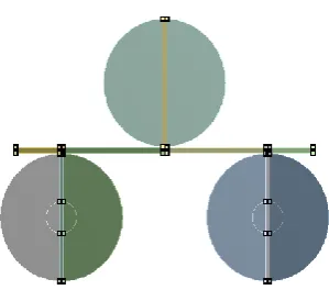
Fig. 3. Plane stress model for rolling process 1.5 mm sheet.
Fig. 4. Meshing for 3 roller bending process.
Top roller is modeled 0.1 mm away from the plate, and frictional contact is used between top roller and plate surface. Other two rollers are assumed to have bonded contact with plate surface. Finer meshing size is used at top roller for contact region and plate as it is our area of interest. Bottom two rollers are fixed at inside circle of 10 mm diameter. Displacement to the top roller will be used as boundary condition. Non- Linear mild steel properties from ANSYS library are used for plate. It uses bilinear hardening plasticity to define stress strain curve beyond yield limit.
629 | P a g e
Table I. Material properties for mild steel [11].
Property Value Unit
Modulus of Elasticity 205 E3 M Pa
Poisson's Ration 0.29 -
Yield Strength 180 M Pa
Ultimate Tensile Strength 440 M Pa
Fig. 5. Boundary condition and Loading.
Fig.7. Maximum Strain Plot for top roller displacement 1mm.
Spring Back effect can measured in ANSYS as difference between maximum deformations of the sheet at top roller displaced and maximum deformation at the end of the cycle.
Spring Back Effect = 0.90-0.6477 Spring Back = 0.2533 mm
631 | P a g e
Fig. 9. Total Deformation plot after roller retrieved back.
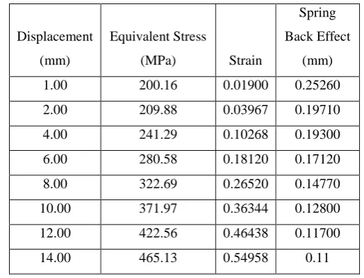
Table II.FE Analysis result - stress and strain for sheet thickness of 1.5 mm.
Displacement (mm)
Equivalent Stress
(MPa) Strain
Spring Back Effect
(mm)
1.00 200.16 0.01900 0.25260
2.00 209.88 0.03967 0.19710
4.00 241.29 0.10268 0.19300
6.00 280.58 0.18120 0.17120
8.00 322.69 0.26520 0.14770
10.00 371.97 0.36344 0.12800
12.00 422.56 0.46438 0.11700
14.00 465.13 0.54958 0.11
IV. EXPERIMENTAL VERIFICATION
4.1 Three Roller bending set up
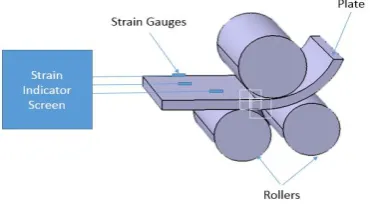
Fig.10.Schematic Block diagram for testing on three roller bending machine.
Fig.11. Experimental Set up for testing on three roller bending machine
.4.2 Experimental Result
Table III. Results of testing.
Top Roller Displacement
(mm) Strain Observed
2 0.036
4 0.098
6 0.162
8 0.245
10 0.335
12 0.426
14 0.533
From the above table III, we have proved that the strain values observed in experimental result with FEA result with marginal acceptable error.
V. RESULTS AND DISCUSSIONS
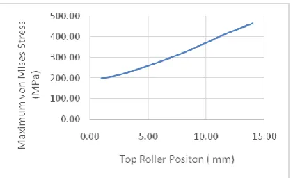
633 | P a g e found in work piece while 14 mm displacement of top roller is 465 MPa which is more than the ultimate tensile strength of the mild steel. Variation of maximum von Misses Stress in the plate with respect to change in top roller position as shown in figure below from table II.
Fig.12. Displacement of top roller position V/s Maximum von Mises Stress.
Graph below from table II shows the relation between spring back effect of the plate and top roller position while rolling. Spring back effect reduces as top roller position is advanced downward.
Fig.13.Displacement of top roller position V/s spring back effect.
Strain values observed from analysis and testing strain values are compared to find the error % or deviation of the strain from testing values. Maximum of 15 % deviation from the actual values is considered good correlation with FEA.
Table IV. Comparison of analysis result and experimental result.
Displacement
(mm) Strain % Error
Analysis Testing
1.00 0.01900 0.017 10.53%
2.00 0.03967 0.036 9.25%
4.00 0.10268 0.096 6.51%
6.00 0.18120 0.162 10.60%
8.00 0.26520 0.245 7.62%
10.00 0.36344 0.335 7.83%
12.00 0.46438 0.426 8.26%
In the above table IV the simulation results are compared with experiments performed with three roll bending machine. Maximum displacement of top roller allowed without endangering crack formation in the range of 1 mm to 12 mm from experimental and FEA results. From FEA and practical results comparison strain values are in conformance with each other
Fig.14. Comparison of FEA result V/s Experimental result.
VI. CONCLUSION
We have calculated the diameter of the roller required for bending maximum of 2 mm thickness sheet is 30 mm. With given configuration of 30 mm roller diameter with 54 mm roller distance we can bend 1.5 mm mild steel plate up to roller position of 12 mm without any cracks on the sheet metal
Strain values observed in FEA and testing are pretty much in conformance which validates the FEA model. Valuable prediction of maximum stress, spring back effect and strain values is generated for different top rollers positions while bending 1.5 mm thick mild steel plate using this three roller bending machine.
A. Future Scope
Different thickness varying below 2 mm can be modeled and similar data can be generated for all possible gauge thicknesses of sheet.
Different material can be tested and validated in FEA and testing and data for them can be generated. Data generated can be used to graphically predicting the minimum radius of curvature each type of material
and thickness of sheet can achieve on particular bending machine without generating cracks on the work piece.
MATLAB program can be used to predict mathematical values of radius of curvature for different sheet thickness and different roller positions.
R
EFERENCES[1] Chudasama, M. K. and Raval H. K. 2012, “Analytical model for prediction of force during 3-roller multipass conical bending and its experimental verification”. International Journal of Mechanical Engineering and Robotics Research, Vol.1, No.3, p.91-105.
635 | P a g e [3] Fu, Z., Tian X., Chen W., Hu B. and Yao X. 2013, “Analytical modeling and numerical simulation for
three-roll bending forming of sheet metal”. The International Journal of Advanced Manufacturing Technology, Vol.69, No.5-8, p.1639-1647.
[4] Gajjar, H. V., Gandhi A. H., Jafri T. A. and Raval H. K. 2007. “Bendability analysis for bending of C-Mn steel plates on heavy duty 3-roller bending machine” World Academy of Science, Engineering and Technology, Vol.1, No.8, p.86-91.
[5] Gandhi, A. H., Shaikh A. A. and Raval H. K. 2008. “Analytical and empirical modeling of top roller position for three-roller cylindrical bending of plates and its experimental verification”. P. 268–278. [6] M. Hua, D.H. Sansome, K.P. Rao, K. Baines, Continuous four-roll plate bending process: it’s bending
mechanism and influential
parameters, J. Mater. Process. Technol. 45 (1994) 181-186.
[7] Firat M (2007), “Computer Aided Analysis and Design of Sheet Metal Forming Processes: Part II – Deformation Response Modeling”Materials and Design, Vol. 28, pp. 1304-1310.
[8] Gandhi A H, Gajjar H V and Raval H K (2008), “Mathematical Modelling and Finite Element Simulation of Pre-Bending Stage of Three-Roller Plate Bending Process”, MSEC 2008, doi:10.1115/ MSEC_ICMP2008-72454, pp. 617-625.
[9] Hua M., Sansome D.H., Baines K., Mathematical modeling of the internal bending moment at the top roll contact in multi-pass four-roll thin-plate bending, Journal of Materials Processing Technology, 1995, Vol-52, pp. 425-459.
[10] M. B. Bassett, and W. Johnson, “The bending of plate using a three roll pyramid type plate bending machine”, J. strain Analysis, vol. 1, no. 5, pp. 398, 1996.
![Table I. Material properties for mild steel [11].](https://thumb-us.123doks.com/thumbv2/123dok_us/9255784.1463124/5.595.187.409.111.380/table-i-material-properties-mild-steel.webp)