Published online June 10, 2013 (http://www.sciencepublishinggroup.com/j/ijssn) doi: 10.11648/j.ijssn.20130103.12
A web-based remote indoor climate control system based
on wireless sensor network
Jingcheng Zhang, Allan Huynh, Patrik Huss, Qin-Zhong Ye, Shaofang Gong
Department of Science and Technology, Linköping University, Bredgatan 33, 60174, Norrköping, Sweden
Email address:
[email protected](J. Zhang), [email protected](A. Huynh), [email protected](P. Huss), [email protected](Q. Ye), [email protected](S. Gong)
To cite this article:
Jingcheng.Zhang, Allan.Huynh, Patrik.Huss, Qin-Zhong.Ye, Shaofang.Gong. A Web-based Remote Indoor Climate Control System Based on Wireless Sensor Network. International Journal of Sensors and Sensor Networks. Vol. 1, No. 3, 2013, pp. 32-40. doi: 10.11648/j.ijssn.20130103.12
Abstract:
This paper presents the design and implementation of a web-based wireless indoor climate control system. The user interface of the system is implemented as a web service. People can login to the website and remotely control the indoor climate of different locations. A wireless sensor network is deployed in each location to execute control commands. A gateway is implemented to synchronize the information between the wireless sensor network and the web service. The gateway software also includes scheduling function and different control algorithms to improve the control result. Additionally, the system security and availability are highly considered in this system. The gateway software implements a warning function which sends warning messages when emergency happens. Finally, the whole wireless control system architecture is modularly designed. It is easy to add different control applications or different control algorithms into the system.Keywords:
Remote Control, Indoor Climate, Wireless Sensor Network1. Background Introduction
Indoor climate control is very important for human comfort and health. Nowadays, almost all new buildings are installed with heating, ventilation and air conditioning (HAVC) systems which provide a good indoor air quality. However, the situation can become more complicated when providing a similar indoor climate for old buildings. Firstly, some old buildings have very high heritage preservation values so that no modification or reconstruction is allowed. Secondly, some old paintings or wooden carvings are sensitive to temperature and relative humidity change. The climate control process should be done as smooth as possible. Thirdly, some of the old buildings, e.g., churches, are not used every day. In order to save power consumption, it is only necessary to set the indoor climate into a comfort level when some activities are scheduled. Finally, from practical point of view, one person might need to maintain several old buildings. These old buildings could be hundred kilometers away from each other. It is a big waste and low efficiency to travel among different buildings to do manual control.
Many research efforts have been done in the wireless
control area[1] -[9]. However, by the time when this paper is written, no scientific report has been found on using wireless sensor network to control the indoor climate of cultural heritage buildings. As described above, a system that can solve all mentioned problems should have the following features:
• A wireless control system which requires minimum reconstruction of the building during the installation. • A wireless controller should be easy to be reused for
different control purposes.
• A system which provides schedule function. The system should be able to change the indoor climate according to the user booking.
• A system that can be remotely accessed.
2. Remote Control System Architecture
Description
As shown in Figure. 1, the “CultureBee” system contains three parts, the “wireless sensor network” part, the “local server” part and the “web service” part. The web service provides a website user interface. Users can login to the website to control the indoor climate of different locations. For one specific location, a local server and a wireless sensor network are deployed. The local server works as a gateway between the web service and the wireless sensor network. It communicates with the “root node” of the wireless sensor network via the USB port. It also communicates with the main server via the Internet. The sensor node of the wireless sensor network reports the indoor climate measurement to the local server periodically. The wireless controllers in the sensor network are connected with radiators or dehumidifiers according to the controller type. They listen to the command from the local server and control the indoor climate.
Figure 1. “CultureBee”control system architecture
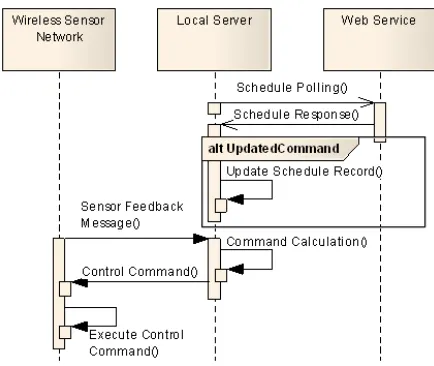
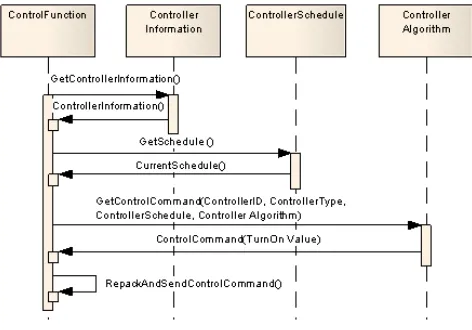
Figure. 2 shows the control function message flow within the “CultureBee” system. In order to get scheduling messages from the web service, the local server sends the “schedule polling” message to the web service periodically. When a control schedule is issued, the web service stores the schedule until the polling message from the local server
Figure 2. Control function message flow
is received. The schedule is then sent to the local server as the response of the polling message. Once the schedule is received, the local server updates the local schedule configuration accordingly. Meanwhile, if a feedback sensor message is received by the local server, the control command is calculated by the local server according to the local control schedule. The control command is forwarded from the local server to the wireless sensor network.
3. Wireless Sensor Network
The wireless sensor network of the “CultureBee” system mainly works for three purposes: collecting the sensor information for the local server, executing the control command sent from the local server and increasing the communication reliability of the wireless sensor network. Compared with the local server, the computational capability of the wireless device is much lower. In order to optimize the system performance, the wireless sensor network control function is designed to be as simple as possible. Most of the control logics and management functions are implemented in the local server.
3.1 Devices of Wireless Sensor Network
The CultureBee wireless sensor network utilizes the ZigBee protocol to transmit sensor information and climate control commands. A ZigBee wireless sensor network can contain 3 different kinds of devices: coordinator, router and end device. The coordinator is the root and creator of the network. A router works as a message relay to extend the network scale. An end device can enter sleep mode from time to time to save power. The end device is the only one that can be battery powered.
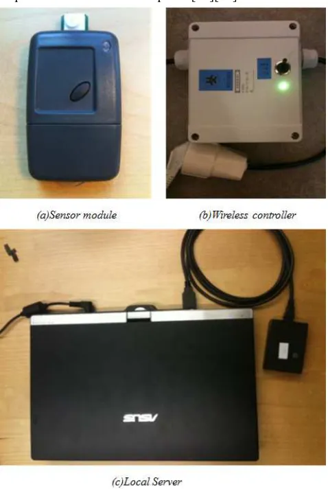
network scale, routers can be used to establish a multi-hop sensor network[12]. As defined by the ZigBee protocol, a router needs to be mains-powered so that the radio part can be always active. The wireless controller function is also developed base on the ZigBee router program. From the hardware point of view, as shown in Figure.3 (b), the wireless controller is a power relay which can only switch On/Off the power at the output. However, different control algorithms can be emulated by carefully selecting the switch-on interval. The coordinator is the root of the network. As shown in Figure. 3(c), it communicates with the local server via the USB port. In order to increase the radio range, all devices are equipped with a power amplifier and a low noise amplifier[13][14].
Figure 3. Wireless sensor network hardware
3.2. Wireless Sensor Network Message Flow
Figure. 4 shows the control function message flow of the wireless sensor network. In order to increase the communication reliability, all the wireless devices run together with the “stability enhancement” state machine[15]. From the control function point of view, the message flow can be categorized into “controller registration” cluster and “close loop control” cluster.
Figure 4. Wireless sensor network control function message flow
The “controller registration” message is sent by a wireless controller which newly joins the wireless sensor network. This message provides the wireless controller description to the local server. When the local server receives the message, the local server saves the registration information into its local database. Figure.5 shows the format of the “controller registration” message frame. The “Message Header” field identifies the message type which can be recognized by the local server. The “Network Address” filed contains the unique ZigBee network address[16]. The “Node ID” field contains the wireless controller device ID which is utilized by the control application. It is a unique ID all through the CultureBee system.
Figure 5. Wireless controller registration message format
Figure 6. Control command message format
For each control command, the wireless controller issue two acknowledgements to the coordinator. As shown in Figure. 4, the first acknowledgement is sent directly after the controller receives the control command. It informs the local server that the message is successfully received and executed. The second acknowledgement is sent when the command is expired. In the normal case, the time difference between the two consecutive acknowledgements should equal to the value of the “Interval” field described in Figure. 6. The frame format of the acknowledgement message is shown in Figure.7. The “Message Header” field identifies the message. The “Controller Status” field reports the On/Off status of the wireless status. If errors are detected by the wireless controller, the error code is also carried in the “Controller Status” field and sent to the local server.
Figure. 7 Control command message format
4. Local Server Design
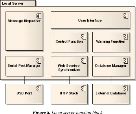
The local server is the gateway between the wireless sensor network and the web service. It is a software program that runs on the Windows operating system. As shown in Figure 8, the local server communicates with the operation system mainly via three interfaces: the USB port interface which exchanges messages with the coordinator, the HTTP stack interface which synchronizes messages with the main server and the database interface which manages the local server control information. The local server also provides a local user interface so that the control system can be locally configured when the Internet is not available.
Figure 8. Local server function block
As shown in Figure. 8, the local server functions are implemented by different function components. The “serial
port manager” component handles the communication between the local server and the coordinator. When the local server receives a serial message, the “serial port manager” forwards the message to the “message dispatcher” component. The “message dispatcher” works for all the message exchange within the local server. It parses and redirects the messages to the correct component according to the received message type. The “web service synchronizer” component is implemented to synchronize messages between the wireless sensor network and the main server. Generally, the “web service synchronizer” forwards the sensor message from the local server to the main server. It also sends polling message to the main server to ask for pending control schedules. Once the control schedule is received, the “web service synchronizer” forwards the schedule to the “message dispatcher” for further process. The “control function” component is the central software module that manages all the control operations. It contains the logic to generate the command to control the wireless sensor network with different control algorithms. The “warning function” component checks the status of the wireless device and sends out warning message when emergency happens.
4.1. Control Function Component Design
The goal of the “control function” component is to implement an easy to configure and high flexibility control system. A database is utilized to store the control information. An expandable design pattern[17] is applied on implementing the control algorithms. The whole local server control operations are managed by a software state machine.
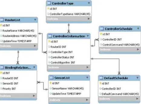
4.1.1. Control Function Database Design
It states which router is programmed as a wireless controller. The “controller type” field refers to the index of the table “controller type”. It shows the controller type that is connected with the wireless controller. The “controller status” files record the current ON/OFF status of the wireless controller which is reported from the command execution acknowledgement. The climate control schedules are saved in table “controller schedule” and “default schedule”. The “controller schedule” table saves all the user issued schedules which are either synchronized from the main server or configured locally. The “default schedule” table saves the default configurations for each controller. The default schedule will be executed if there is no user specific schedule found by the local server.
Figure 9. Control function database design
4.1.2. Control Function Algorithm Design
The “control function” component is implemented as a control algorithm container. Different control algorithms can be easily added into the component. To implement this mechanism, the “control function” component utilizes a design pattern called “abstract factory”[12]. By using this method, the control function container returns different control algorithms according to the controller configuration. As shown in Figure 10, The “Control Function Base” class is a “generalized based class”[12] which represents the most basic operations for a control algorithm. The function “Find Schedule” helps the program to find the correct schedule from the database. The function “Send Command WSN” sends the calculated command from the local server to the wireless sensor network. Three different control algorithms are implemented in the control function component, the
threshold based control (TH) the
proportional-integral-derivative control (PID) and mold prevention control (MP)[18]. Different control functions are implemented as the “child class” of the “Control Function Base” class. Each control algorithm child class reuses the “Find Schedule” and “Send Command” functions from the base class and implements its own “Generate Command” function. The “Generate Command” function is utilized to calculate the “switch on interval” for the controller based on
the feedback sensor message and controller information. The generated command is further executed in the wireless sensor network, as described in Fig.4.
Figure 10. Control algorithm class diagram
4.1.3. Control Function State Machine
The control function operations are described by the state machines as shown in Figure.11. After start-up, the local server stays the “IDLE” state. Once a sensor message is received, the local server forwards the message to the main server using the “web service synchronizer” component. Then the local server enters the “SYNC” state. In this state, the local server checks the “Binding Relationship” table to get the bind controller list. If no controller is found, the local server jumps back to the “IDLE” state and wait for the next sensor message. Otherwise, the local server jumps to the “CONTROLLR PENDING” state. For each bound controller, the local server generates the specific control command in the “CONTROL PROCESS” state. When the control command is generated, the local server jumps back to the “CONTROL PENDING” state. If there is no more pending controller waiting for the control command, the local server jumps to the “IDLE” state and waits for the next sensor message.
Figure 11. Control function state machine
climate setting. After getting all necessary input information, the control function component sends the “get control command” request to the “controller algorithm” component. Based on the received information, the controller algorithm returns the “control command” with a “Turn On Interval” value. Once the control function component receives this value, it inserts the controller network address in the message and creates the control message as shown in Fig.6.
Figure 12. Function execution in “Control Process” state
4.4. Warning Function Component Design
The local server warning function is designed to notify the user when controller stops responding. Generally, a controller can stop working in two cases. One is that the wireless controller simply stops working. It can be caused by a hardware failure or loss of wireless connection. Another case is that the feedback sensor stops reporting. Normally, one wireless controller is bound with more than one feedback sensors. However, there is still a possibility that all the configured sensors lost the connection with the wireless sensor network. Moreover, the local server should also be able to configure the “sensitivity” of the controller failure. If the controller is very important, user might want to know the problem immediately. If the controllers are not so crucial, it might be considered to be offline after “keeping silence” for an hour.
A reusable wireless device status detection mechanism is designed in the local server to send warning messages. In the wireless sensor network, the sensor modules and the wireless controllers send “heart beat” messages to the local server periodically. Once the “heart beat” message is received, the local server updates the device “update time” field in the “router list” or “sensor list” table in the database according to the device ID. The warning function component is designed as shown in Figure.13. When the “warning function” starts working, it loads data from the warning configuration list. For each record in the list, the “device name” and “MAX_OFF_TIME” are saved. The device name identifies which device is enabled with the warning function in the wireless sensor network. The MAX_OFF_TIME is the threshold for the warning function component to send out warning message. The device list
from the configuration file is loaded to the local server program by calling the function “Register Device” in the “warning function” class. Another function called “check status” is invoked periodically to get “offline device list”. During the function execution, the status of each registered wireless device is checked. A class “device status” is implemented to report the device status according to the device ID. During the status check, the warning function gets the device “Update Time” value from the database. The difference between the current time and “Update Time” of each device is calculated to compare with the “MAX_OFF_TIME”. If the value is bigger than the “MAX_OFF_TIME”, the device is considered to be “offline”. When the local server has gone through the status of all registered devices, it invokes the “Send Warning Message” function to send the “offline device list” through the “web service synchronizer” component.
Figure 13. Warning function class diagram
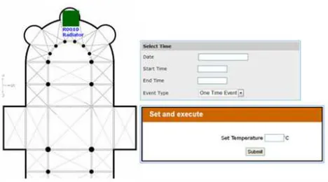
5. Web Service Design
Figure 14. Main server schedule configuration user interface
6. Test Result
The “CulureBee” control system was deployed in 10 different places around Sweden for temperature control, dehumidification control and mold prevention purpose in 2012. A typical use scenario is to control the conference room temperature in VASA museum in Stockholm[19]. As shown in Figure. 15(a), a wireless sensor is placed in the center of the room. It provides the sensor feedback reading to the controller which controls the radiator. The wireless controller, as shown in Figure. 15 (b) is connected with the electric powered radiator.
Figure 15. Wireless control system in VASA museum
Figure 16. Temperature control test result
To control the indoor climate, the temperature is set to 21ºC between 8:00 am to 17:00 pm and keeps 19 ºC for the rest of the time every day. In order to keep the temperature stable, the PID control algorithm is utilized for the controller. Figure. 16Figure (a) shows the one month control result summary. As shown in the diagram, the temperature changes between 19 and 21ºC every day. Figure. 16(b) shows the detailed temperature change within one day. As shown in the diagram, when temperature changes from 19 to 21ºC, the temperature increases fast at the beginning. As the temperature approaching to 21ºC, the temperature increases much slower until the setting is reached. In this case, no temperature vibration is introduced resulting in a much more comfortable and smoother indoor climate control. This is especially good for the heritage preservation purpose.
7. Discussion
dehumidifier to the place where it is necessary. In this case, the system can provide a relatively satisfactory air temperature in the human activity area, while keeping the total air temperature as stable as possible. This can be a good solution for indoor climate control of cultural heritage buildings, museums and summer houses, etc.
The local server contains all the control logic to generate the command for the wireless controller. A centralized control method is utilized in the local controller which requires all the messages to go through the local server. Alternatively, a distributed control mechanism is implemented and compared[20]. The advantage of the distributed control is that the sensors and controllers are paired in different segments. It is self-maintained by the wireless sensor network. It can also work independently from the local server. However, this also brings some problems into the system. Firstly, one feedback sensor might bind with more than one controller. In this case, the battery powered sensor module needs to send the sensor message to multiple destinations. This can reduce the battery life time of the wireless sensor device. Secondly, the wireless sensor needs to handle the control function by its own. As described in 4.1.3, it might be a too heavy task for an 8-bit microprocessor. Finally, if the local server is down, the distributed control mechanism can continue working according to the previous configuration. However, it is impossible for the user to change the configuration during the system down time. Compared with the centralized control system, no more control command will be sent out from the local server when it goes down. Thus the user knows that the control system will shut down if the local server stops working. Compared with the distributed control system, the local server failure is more scalable.
Finally, the “modular design” concept is considered in many places of the “CultureBee” control system. When the wireless controller receives the control command, it only turns on the relay with the specified interval. All the control logic is running inside the local server. In this case, no modification needs to be done when changing the controller type. In the local server, new controller types, new controllers and new feedback sensors and new warning configuration can be easily added by configuring the local server database and configuration files. A “many to many” binding relationship between feedback sensors and wireless controllers is established. It can be easily changed in the database configuration. It is also very easy to change the controller algorithm of the controller and configure the algorithm parameters. In the code level, new control algorithms can be easily added into the control algorithm container. Different control algorithms are implemented as different items inside the local server control function container.
8. Conclusion
A web-based remote indoor climate control system is
developed and implemented for historical buildings. The main server provides a web-based user interface. Users can set schedules to control the indoor climate of different buildings. The local server contains the central logic of the control function. It is modularly designed software which provides high flexibility and re-configurability. The wireless sensor network communication reliability is enhanced. It receives and executes the control commands sent from the local server. The whole system has been proven to be robust. It is particularly suitable for the climate control of the old historical buildings where connecting wires should be avoided.
Acknowledgements
This project is financed by the Swedish Energy Agency (Energimyndigheten) and the Churches of Sweden (svenskakyrkan).
References
[1] Wan-Ki Park, Intark Han, Kwang-Roh Park. ”ZigBee based Dynamic Control Scheme for Multiple Legacy IR Controllable Digital Consumer Devices”, IEEE Transactions on Consumer Electronics, Volume 53, Issue 1, 2007, pp 172-177
[2] Leccese, F. “Remote-Control System of High Efficiency and Intelligent Street Lighting Using a ZigBee Network of Devices and Sensors”, IEEE Transactions on Power Delivery, Volume: 28 , Issue 1, 2013, pp 21-28
[3] Dae-Man Han; Jae-Hyun Lim. ”Smart home energy management system using IEEE 802.15.4 and Zigbee”, IEEE Transactions on Consumer Electronics, Volume 56, Issue 3, 2010, pp 1403-1410
[4] Il-kyu Hwang; Jin-wook Baek. “Wireless access monitoring and control system based on digital door lock”, IEEE Transactions on Consumer Electronics, Volume 53, Issue 4, 2007, pp 1724-1730
[5] Jinsoo Han; HaeRyong Lee; Kwang-Roh Park. “Remote-controllable and energy-saving room architecture based on ZigBee communication”, IEEE Transactions on Consumer Electronics, Volume 55, Issue 1, pp 264-268
[6] Ahmad, A.W., Jan, N., Iqbal, S., Lee, C. “Implementation of ZigBee-GSM based home security monitoring and remote control system”, in 2011 IEEE 54th International Midwest Symposium on Circuits and Systems (MWSCAS), Seoul, Korea (South), 07 Aug - 10 Aug 2011, pp.1-4
[7] Jinsoo Han, Chang-Sic Choi, and Ilwoo Lee. “More Efficient Home Energy Management System Based on ZigBee Communication and Infrared Remote Controls”, in 2011 IEEE International Conference on Consumer Electronics (ICCE), Las Vegas, NV, USA, 9-12 Jan. 2011, pp. 631-632
Portugal, 14 Apr - 16 Apr 2008, pp.1-4
[9] Cui Chengyi, Zhao Guannan and Jin Minglu, “A ZigBee based embedded remote control system”, in 2010 2nd International Conference on Signal Processing Systems (ICSPS), Dalian, China, Jul 5, 2010 - Jul 7, 2010, pp. V3 373-376
[10] ZigBee Alliance (http://www.zigbee.org/)
[11] Jingcheng ZHANG, Allan HUYNH, Qinzhong YE and Shaofang GONG. “Remote Sensing System for Cultural Buildings Utilizing ZigBee Technology”, in 8th International Conference on Computing, Communications and Control Technologies (CCCT2010), April 6th - 9th, 2010, Orlando, USA. pp.71-77
[12] Drew Gislason, ZigBee Wireless Networking, Newnes, 2008.
[13] Allan Huynh, Jingcheng Zhang, Qin-Zhong Ye and Shaofang Gong. “ZigBee Radio with External Low-Noise Amplifier”, Sensors & Transducers Journal, Vol. 118, Issue 7, July 2010, pp.110-121
[14] Allan Huynh, Jingcheng Zhang, Qin-Zhong Ye and Shaofang Gong. “ZigBee Radio with External Power Amplifier and Low-Noise Amplifier”, Sensors & Transducers Journal, Vol. 114, Issue 8, July 2010, pp.184-191
[15] Jingcheng Zhang, Allan Huynh, Qin-Zhong Ye and Shaofang Gong. “A Communication Reliability Enhancement Framework for Wireless Sensor Network Using the ZigBee Protocol”, Sensors & Transducers Journal, Vol. 135, Issue 12, Jan 2012, pp.42-56
[16] Jingcheng Zhang, Allan Huynh, Qin-Zhong Ye and Shaofang Gong. “Reliability and Latency Enhancements in a ZigBee Remote Sensing System”, in The Fourth International Conference on Sensor Technologies and Applications (SENSORCOMM 2010), July 18 - 25, 2010Venice/Mestre, Italy. Pp.196-202
[17] Erich Gamma, Richard Helm, Ralph Johnson, John Vilssides. Design Pattern: Elements of reusable object oriented software. Addison-Wesley Professional, 1st edition, November 10, 1994
[18] Willian L. Brogan. Modern Control Theory, Prentice Hall, 3rd edition, October 11, 1990
[19] VASA museum (www.vasamuseet.se/)