A High Speed Open Access Visible Light
Communication System based on Intensity
Modulation
Sivaguru. S Sundari. B
Assistant Professor Assistant Professor
Department of Electronics & Communication Engineering Department of Electronics & Communication Engineering AVS College of Technology, Salem Tamilnadu, India Jayam College of Engg & Tech, Dharmapuri Tamilnadu, India
Rupavathi.N Associate Professor
Department of Electronics & Communication Engineering Jayam College of Engg & Tech, Dharmapuri Tamilnadu, India
Abstract
A light-emitting diode (LED) light communication system was implemented with a controlling switching light module using the ATmega16 micro-controller. To solve the existing modulation effect and disturbance in visible light communication, an integrated interface was evaluated with a driving light module and analyzes its reception property. A transmitter/receiver using the Atmel's micro-controller, high-intensity white LED-6 modules, and infrared sensor KSM60WLM and visible sensor TSL250RD were designed. An experiment from the initial value of distance to 2.5 m showed 0.46 V of the voltage loss, and if in long distance, external light interference occurred and light intensity was lost by external impact and thus data had to be modified or reset repeatedly. Additionally, data could be transmitted up to 1.76 m without any errors during the day and up to 2.29 m at night with around 2~3% communication error. If a special optical filter can reduce as much external light as possible in the integrated interface, the LED for lighting communication systems may be applied in next generation networks.
Keywords: Light-Fidelity (Li-Fi), Light Emitting Diode (LED), Line of Sight (Los), VLC, Intensity Modulation
________________________________________________________________________________________________________
I. INTRODUCTION
LED-to-LED Visible Light Communication (VLC) based on Light Emitting Diodes (LEDs) and microcontrollers provide a foundation for networking using visible light as communication medium. Recently, the low energy consumption, long lifetime and lower price per unit brightness enable light emitting diode (LED) to replace the conventional lighting for both in-door and out-door. Furthermore, the relatively high modulation speed of the LED permits a short-range communication employing visible light. Therefore, the visible light communication (VLC) can be distinguished from the radio-frequency (RF) communication to provide electromagnetic interference (EMI) free and license-free communications. Thus, using LED lighting system for VLC has attracted more and more attentions [1].
The technology that wireless communication is available wherever there is LED lighting, has recently been developed. In particular, wireless visible light communication (VLC) has drawn much attention these days, especially the LED-based VLC. VLC refers to a communication that uses visible light range which can be seen to the human's eyes, and also a new information and communication technology that using infrastructure in which lightings visible to the human's eyes such as incandescent and fluorescent lightings are replaced by light emitting diode (LED), information is sent to each object and the information sent is reused. In other words, it can be said that VLC is a technology which transmits and exchanges information using lights including visible light range (380~780 nm), or near-infrared ray (700~2,500 nm)range emitting from home lighting, outdoor advertising signs, traffic signals, display of various devices, etc, and a new optical wireless technology differentiated from optical communications through the existing optical fiber.
(Integrated interface using the switching driving module) Then, we implemented the integrated LED interface with a system’s transmitter/receiver to evaluate the applicability of the next generation home network [3]-[6].
II. DESIGN AND IMPLEMENTATION
As LED based lighting technology develops and expands in its distribution, visible light wireless communication technology based on LED lightning will become an area of much interest in the home network industry. In particular, the LED applications were networked with a visible light wireless communication system [7].
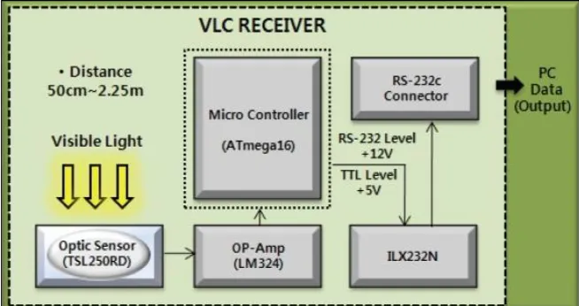
The VLC lighting control system utilizing infrared communication used an infrared remote controller as a medium for communication. The VLC lighting control system utilizing infrared communication used an infrared remote controller as a medium for communication. The VLC transmitter part and VLC receiver part were mounted with an infrared sensor. The system in this study transmits data in the infrared remote controller to the VLC transmitter part mounted with an infrared sensor [8]-[10]. The data are converted into transistor-transistor logic (TTL) signal by the ILX232N chip and sent through micro-controller to LED emitting part. Through the VLC emitting part, the LED, data are sent to the visible light reception sensor in the VLC reception part and OP-amp circuit amplifies the weak electrical data signal which is transmitted to the PC via the RS-232C cable through the microcontroller and ILX232N chip.
VLC Transmission
Fig. 1: Visible light communication (VLC) transmission access block diagram.
The block diagram of the VLC transmission part is shown in Fig. 2. It consists of infrared sensor KSM60WLM, MCU ATmega16 chip, high intensity LED module (6 pcs), and ILX232N chip, which is used for TTL signal level conversion. The infrared remote controller sends a data signal through IR sensor KSM60WLM and the signal is converted by the ILX232N chip to the TTL signal level and sent through the micro-controller to the LED emitting part.
VLC Reception
The VLC reception part consists, as shown in Fig. 3, of TSL250RD and MCU ATmega16 chip, which are visible light reception sensors used to receive data signal sent from LED. The data signal received through the visible light reception sensor is sent through MCU and OPAMP LM324N chip to the PC.
VLC LED Transmitter Driver Circuit
Fig. 3: VLC LED Transmitter Driver Circuit
VLC Photodiode Receiver Circuit
Fig. 4: VLC Photodiode Receiver Circuit
III. PROTOTYPE OF HARDWARE
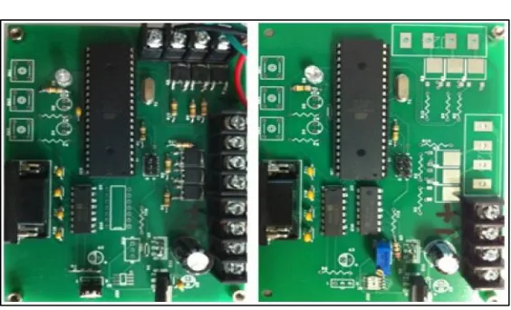
Fig. 5: Hardware Implementation of VLC
After examining the characteristics of the 2N4401 transistor, the transistor can work in MHz frequency range. It is not a problem for this model design, since MAX3222 is designed to work up to 120Kbps which is approximately 50 kHz frequency [11]. R3 is introduced to divert the collector-base leakage current (ICBO), which flows from the collector to the base of the transistor. If this current is not diverted, it will flow from the collector into the base emitter junction, which will lead it to act as a base current coming from outside [12][13]. This can be a problem because this base current can amplify the transistor’s gain. By placing R3 between the base to ground, it will divert the leakage current to the ground instead of going into the base-emitter junction. The receiver side has a voltage regulator, level shifter and the photodiode driver circuit. The output of the receiver circuit is fed to the pin 12 (T1IN) and the pin 15 (T1OUT), where the voltage levels are converted from TTL TO RS-232, is fed to the DB-9 pin 2 (receiver) [14].
IV. RESULTS AND DISCUSSION
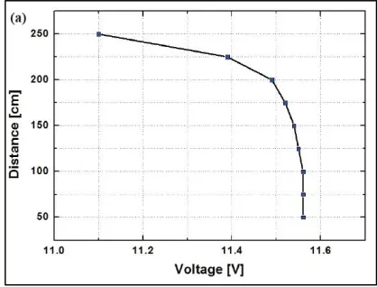
The experimental configuration shown in Fig. 6 was adopted to evaluate the performance of the lighting dimming-based VLC system. Time varying scope and a power intensity system were used to measure the voltage detected at the visible light reception sensor during the day and at night indoors. As the distance between reception and transmission increases, the signal level at the reception part reduces. In this experiment, communication at a distance of 2.25 m or more was weak or nonexistent, so the maximum communication distance was 2 m or so. In this experiment, for stable data transmission, the distance between the two transceivers was 50 cm, data was 8 bit, and in the state of non-parity bit and flow control, the transmission speed was 9,600 bps. At a distance of 2.25 m or more, it was difficult to receive data accurately due to weak intensity of light, but the data transmission process had no problems.
Fig. 6: Characteristics of voltage Vs Distances
V. CONCLUSION
The hyper - terminal was used for sending serial data through computer comports. The serial communication between two computers has been obtained with the maximum 10cm distance between the LED and the photodiode. RS-232 configuration speed of 115200bps.The 10cm is pretty small and is not good enough. To improve the range between the transmitter and the receiver, more LEDs have been used instead of the single LED. This thesis demonstrated a solution to the problem of integrating Visible Light Communication technology with present infrastructure, without having to make major changes to that infrastructure. The proposed system was segmented into two parts with different interface protocols and was demonstrated practically. The prototype can be used to implement a tunable VLC system as the average brightness of the LED can be controlled while transmitting data. VLC will be able to solve many of the problems people have been facing for many years, mainly environmental and power usage issues.
VI. FUTURE SCOPE
Light Fidelity is the future of communication. It is a fast and cheap system of communication and an optical version of LiFi. It will increase the speed of wireless data communication. This project has very wide scope in near future as it can help.
REFERENCES
[1] Harald Burchardt, Nikola Serafimovski, Dobroslav Tsonev, Stefan Videv, and Harald Haas, “VLC: Beyond Point-to-Point Communication,”
Communications Magazine, IEEE, 52(7), pp. 98-105, July 2014.
[2] Xu Bao, Guanding Yu, Jisheng Dai, Xiaorong Zhu, “Li-Fi: Light fidelity-a survey,” Wireless Networks, Springer, pp 1-11, January 2015.
[3] N.Navyatha, T.M.Prathyusha, V.Roja, M.Mounika, “Li-Fi (Light fidelity)-LED Based Alternative”, International Journal of Scientific & Engineering
Research, Volume 4, Issue 5, ISSN 2229-5518, pp. 1039-1042 May 2013.
[4] Akshit Aggarwal, Deepali Jhanji, “ COMPARATIVE STUDY : LI-FI V/S WI-FI,” International Journal of Research & Development in Technology and
Management Science, Volume - 21 Issue 1, March 2014.
[5] Kanchan Gupta, Kajal, Ashish Saini, “Light Fidelity Technology- A Review,” International Journal of Research (IJR), Vol-1, Issue-10 pp. 135-139,
November 2014.
[6] W. Xiao and R. Ratasuk,- Analysis of Hybrid ARQ with Link Adaptationǁ, Proceedings of the Annual Allerton Conference on Communications, Control
and Computing pp. 1618-1619, Oct 2002.
[7] Visible-light communication: Tripping the light fantastic: A fast and cheap optical version of Wi-Fi is coming". The Economist. 28 January 2012. Retrieved
22 October 2013.
[8] Y.-S. Kuo, S. Verma, T. Schmid, and P. Dutta, “Hijacking power and bandwidth from the mobile phone’s audio interface,” in Proceedings of the First ACM Symposium on Computing for Development, ser. ACM DEV ’10. New York, NY, USA: ACM, 2010, pp. 24:1–24:10.
[9] C. Danakis, M. Afgani, G. Povey, I. Underwood, and H. Haas, “Using a cmos camera sensor for visible light communication,” in Globecom Workshops
(GC Wkshps), 2012 IEEE, Dec 2012, pp. 1244–1248.
[10] G. Corbellini, K. Aks¸it, S. Schmid, S. Mangold, and T. R. Gross, “Connecting networks of toys and smartphones with visible light communication,” IEEE
Communications Magazine, vol. 52, no. 7, pp. 72–78, 2014.
[11] P. Dietz, W. Yerazunis, and D. Leigh, “Very Low-Cost Sensing and Communication Using Bidirectional LEDs,” in UbiComp 2003: Ubiquitous
Computing, vol. 2864, 2003, Book Section, pp. 175–191.
[12] http://Technopits.blogspot.comtechnology.cgap.org /2012/01/11/a-li-fi-world/
[13] Luicom. (2014) Luciom, presentation at International CES in Las Vegas. 10-July-2014.