A DESIGN APPROACH FOR TANGIBLE USER INTERFACES Bernard Champoux (Associate Researcher)
Dr Sriram Subramanian (Assistant Professor) Department of Computer Sciences Human Computer Interaction Lab
University of Saskatchewan Saskatoon, Canada
ABSTRACT
This paper proposes a mechanism to design Tangible User Interface (TUI) based on Alexander’s (1964) design approach i.e. achieving fitness between the form and its context. Adapted to the design of TUIs, the fitness-of-use mechanism now takes into consideration the potential conflicts between the hardware of the artifact (electro-mechanical components) and the form of the user’s control (Physical-ergonomics). The design problem is a search for an effortless co-existence (fitness-of-use) between these two aspects. Tangible interface design differs from traditional graphical interface design as unsolved conflicts between hardware and ergonomics can deeply affect the desired interaction. Here we propose a mechanism (in the form of eight questions) that support the design by defining the boundaries of the task, orienting the hardware (electro-mechanics) and ergonomics of the design space for various sub-tasks and finally fitting the different components of the hardware and physical-ergonomics of the artefact to provide a component level fitness which will delineate the final tangible interfaces. We further evaluate the effectiveness and efficiency of our approach by quantitative user evaluation.
Keywords
Tangible user interface, tangible computing, design approach, collaborative design.
INTRODUCTION
A research direction in Human-Computer Interaction that has re-surfaced in the last decade is the use of physical real-world artefacts to represent and control digital data. Tangible user interface is the popular term used to refer to such computing systems that use physical artefacts as representation and control of digital data (Ullmer and Ishii, 2000; Dourish, 2001). Research in tangible user interface has broadly focused on developing systems for various application domains and proposing different frameworks to classify the different systems. Systems have been developed to exploit tangible user interfaces for desktop metaphor (e.g., Neurosurgical Props from Hinckley, 1994), virtual reality metaphor (e.g., Cubic Mouse from Frolich and Plate, 2001) or mixed reality metaphors. (e.g., DataTiles from Rekimoto, 2000). Frameworks have been proposed based on the type of interaction supported (continuous vs. discrete) (Ullmer, 2002) and level of mapping between the physical artefact and digital data (Wensveen et al, 2004).However, to make tangible user interfaces a viable real-world interface by truly targeting users’ needs, a mechanism to facilitate the design of tangible interfaces and their prototyping is required. While software engineers have mature software thinking, referring to the functionalities’ structure and software interface in the desktop space, a tangible thinking, referring to the dynamics’ structure in the real-world space, is still in its infancy.
PURPOSE OF THE DESIGN MECHANISM
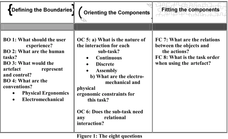
the task and their compatibility with the available sensor technology. How to combine hardware and their usability constraints to create a tangible interface? The mechanism proposed in this paper, when used by a team of experts, aims to provide a workflow in this process and would result in a set of clear and coherent decisions, i.e. clear specifications and/or a functional diagram that works coherently with the necessary tasks. Structured through eight questions in three phases: defining the boundaries (BO 1-2-3-4), orienting the components (OC 5-6) and fitting the components (FC 7-8), the mechanism will ease the location of problems that occurs during the development, facilitate their identification with the mechanism terminology (boundaries, orienting and/or fitting problem) and help their formulation i.e. asking to the right expert the right question. Finally, a completed process will be the starting point to craft a S-Type (specifications) prototype to verify the co-efficiency between the required tasks, their interaction and the needed mechanicals components. The design team will then know how well the fitness-of-use has been achieved and will be able to use their answers to the questions as a checklist. We believe this approach to be an excellent solution to propose “tangible thinking” to students and to help experts in managing their projects. Figure 1 summarizes the eight questions and the next section presents the fitness-of-use problem.
BO 1: What should the user--- experience? BO 2: What are the human tasks?
BO 3: What would the artefact ---represent and control?
BO 4: What are the conventions?
• Physical Ergonomics • Electromechanical
OC 5: a) What is the nature of the interaction for each ---sub-task?
• Continuous • Discrete • Assembly
b) What are the electro---mechanical and physical --- ergonomic constraints for ---this task?
OC 6: Does the sub-task need any ---relational interaction?
FC 7: What are the relations between the objects and ---the actions?
FC 8: What is the task order when using the-artefact?
Figure 1: The eight questions ORIGIN OF THE 8 QUESTIONS
development of the artefact. However, when working with an idea, dealing with a functional diagram is far more easier (and cheaper) than constantly changing the real things.
THE FITNESS-OF-USE PROBLEM
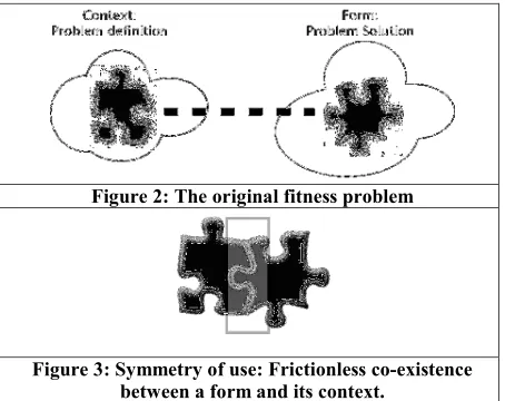
Every design problem begins with an effort to achieve an appropriate fit between two entities: the form in question and its context (Alexander, 1964). A form is the desired solution to the problem and the context defines the problem (see Figure 2). The appropriate fit between the two entities results in an object with symmetry of use properties: effortless contact between the form and the context. (See Figure 3).
Figure 2: The original fitness problem
Figure 3: Symmetry of use: Frictionless co-existence between a form and its context.
In TUIs, this symmetry of use should occur between the physical artefact (form) that represents and controls information and the application (context and the suitable interaction) that defines the digital information: Fitness-of-use (see Figure 4). This is also evident from the MCR-pd interaction model proposed by Ishii and Ullmer (2000), which highlights a bridge between the physical world of atoms and the digital world of bits.
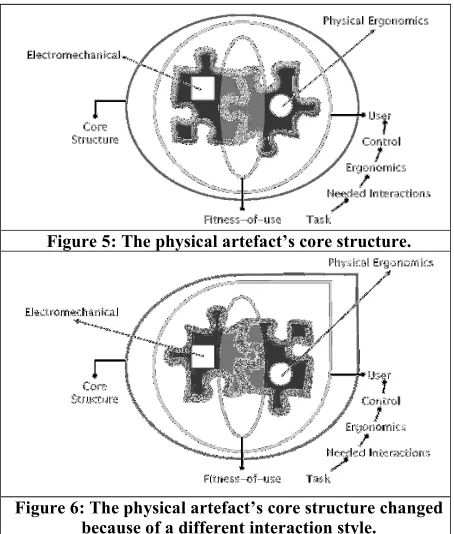
This fitness-of-use problem is confounded by the potential conflict between the hardware (electromechanical components like sensors and actuators that go into the physical artefact) and ergonomics (how the user will use and control the artefact: the interaction) of the design space. The problem is to find out what sensors fit into the artefact and how to fit them so that the ergonomics of the artefact are not compromised. The user’s ability to control the artefact is dictated by the ergonomics, which in turn are dictated by the interactions required by the task. In contrast, the ability of the artefact to control the digital information is dictated by the electromechanics. Thus, the fitness-of-use problem is also transformed into finding a frictionless co-existence of the physical ergonomics of the artefact and its electromechanics. Achieving the fitness-of-use in TUI design aims to create “a vehicle by which the user acquires/constructs a meaning” of the application (Kaptelimin et al., 1981). In order to do so, our mechanism will define the core structure of a physical artefact by addressing the fitness-for-use problem between the appropriate set of interaction needed for the task and their compatibility with the available sensor technology. The potential interactions that occur during the use of the physical artefact highly influence the core structure of the device. Any change in the interaction style signifies a change in the core structure.
Figure 5: The physical artefact’s core structure.
Figure 6: The physical artefact’s core structure changed because of a different interaction style.
and physical ergonomic requirements of the artefact. These are then oriented depending on whether continuous or discrete interaction will be supported for each sub-task. This orients the fit between the various electromechanical components and the desired artefact ergonomic. In the third phase, fitness between the electromechanics and the ergonomics of artefacts is achieved at the component level, which is subsequently prototyped for testing and validation purposes.
RELATED WORK
Brensen (2001), proposed the Modality Theory to allow developers to decide which input and output modalities to use for interaction. The Modality Theory provides a comprehensive analysis of all available modalities in the media of graphics, acoustics and haptics and can suggest a set of input and output modalities for a given application. However, the theory does not address the design of the final realization.
Bellotti et al., (2002), pose five questions that any developer of a sensing systems should address, for improved usability of their ubiquitous or tangible computing system. These questions, which relate to initiating an interaction, specifying the actions and overcoming misunderstandings, are mostly focussed on the final outcome of the interaction and do not deal with specifying the requirements for designing the dynamics of the interaction.
Scenario-based design (Carroll et al., 1998) provides an advanced vision of an application. It creates a set of interaction requirements that can be used to design the application. However, it does not provide a means to factor in electromechanical constraints that might occur when designing tangible user interfaces for the application.
THE MECHANISM Defining the boundaries
One of the fundamental requirements is the ability to layout the parameters of the design space. These parameters specify the boundaries within which the TUI solutions are sought. To layout these parameters, we need to define the desired user experience, the resulting human tasks, and the digital information that will be represented and controlled. All of the team members have an opinion on how a task should be accomplished and what are the required interactions. Once completed, this phase will enable the team to verify the coherency between the interaction and the chosen technology.
User Experience
The desired user experience is usually the starting point for such a design process. On most occasions this comes from observations of everyday environments and tasks, with a desire to augment the environment with sensors that will modify and enhance the user’s experience in interacting with them. For example, in mediaBlocks (Ullmer et al., 1997), one of the experiences sought was to use real-world gestures to manipulate digital media (multimedia presentation, video etc.) without the need for an explicit computer.
Human Tasks
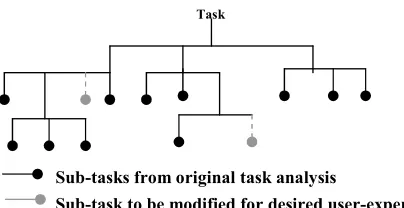
currently interact with digital media and identifying possible tasks that can be modified. Ullmer et al., (1997) chose to modify the current practice of capturing, transporting and reviewing pieces of digital media to achieve their desired user experience. The task analysis tree also suggests the possible ergonomic constraints the application might impose on the design.
Artefact representation and control
By analysing the user experience the designer can also identify the different digital information that needs to be represented and controlled by the user. The task analysis tree also specifies details of the digital information that will be controlled by each sub-task. Based on this information, the designer can identify the specific sensors and actuators needed for physical control of the digital information. This will also suggest how impractical a physical control might be for certain digital information, thereby laying out the electromechanical constraints of the design space. At this stage, the sensors used are specified at a broad level (i.e., the designer knows s/he needs a force sensor and not a light sensor) without knowledge of the specific details of the sensor (what kind of force sensor, how many newtons etc.)
Conventions
A consequence of analysing the design space is a realization that we make many assumptions about the user expectations and interactions. It is always useful to step out of the design process to reflect on the possible conventions that might be taken for granted. These conventions might impose newer constraints on the ergonomics or electromechanics of the design. For example, in mediaBlocks, the user is assumed to carry the mediaBlock. This imposes weight and size restrictions on the block. While in this case the constraint is fairly easy to deduce, it might not always be the case.
Usually, defining the boundaries of our design space is an iterative process. The user experience desired will inevitably be refined after due consideration to the human tasks and the desired physical control. The following four questions can be used as a general guideline for laying out the boundaries of the design space.
1. What should the user experience? 2. What are the human tasks?
3. What would the artefact represent and control? Task
Sub-tasks from original task analysis
Sub-task to be modified for desired user-experience
4. What are the conventions?
The next step in the design process is to take a closer look at the sub-tasks that need to be modified. These electromechanical and the ergonomic constraints have to be aligned with each other based on the nature of the tangible interaction suited for these sub-tasks.
Orienting the components for desired fitness-of-use
Ullmer (2002) has proposed a framework for Tangible Interfaces that identifies three classifications: Interactive Surfaces, Token+Constraint and Constructive Assemblies. This classification is partly based on the varying degree of support for continuous and discrete forms of interaction. More specifically, interactive surfaces support continuous interaction; token+constraint systems support a combination of (constrained) continuous and discrete interactions, while constructive assemblies almost never support continuous interaction but are instead aimed at discrete interactions.
Nature of the Interaction
This part of the mechanism establishes the nature of physical interaction for each sub-task. The user control imposes newer constraints on the specifics of the sensors and actuators required for the electromechanics of the physical artefact. When designing physical artefacts for continuous interaction, the sensors will need to collect data at a higher frame-rate than when dealing with constructive assemblies. Similarly, depending on the kind of user action supported, the physical artefact might need to be wireless.
This part also provides newer insights into the ergonomics of the final design. For example, when designing for continuous interaction on the table top, the weight of the physical artefact might not be a concern whereas the ability of the artefact to slide on the table-top might be an important physical ergonomic constraint. Similarly, when designing physical artefacts with discrete control, the designer might have to provide mechanisms to restrict the user’s movement of the physical artefact to discrete grids.
In the case of mediaBlocks, a token+constraint approach is used to design the interactions. The following two questions may be used as a guideline for orienting the dynamics of the interaction:
5. What is the nature of the interaction for each sub-task? Will the sub-task require continuous or discrete interaction? What are the electromechanical requirements for this task and what are the ergonomic constraints for this task?
6. Does the sub-task need to have any relational interaction? If two or more physical artefacts are combined to perform the sub-task, will the combination be interpreted in a relational manner: two artefacts together result in adding the corresponding digital information? At this point one has identified the various electromechanical and physical ergonomic components for the tangible interface. The next step to gather all the elements: required tasks and context and to verify how they fit together. This is achieved by integrating the sub-tasks with the rest of the tasks in the task analysis tree with the available technology (Questions 7 and 8).
Fitting the components: Integrating the sub-tasks to the task analysis tree
sub-tasks but also provide detailed questions for a better fit between the electro-mechanics of the artefact and the ergonomics. The five questions are
• How does the user initiate (and terminate) interaction with the artefact?
• How does the artefact inform the user that it realizes that the user has initiated interactions with it?
• What are the user actions to which the artefact can react?
• How does the artefact inform the user that it has understood the user’s actions and is responding to it?
• How can the user recover from a mistake or misunderstanding?
Task order vs. artefact use order
At this point one should have the entire task analysis tree with the modified sub-tasks and the relevant electro-mechanical components identified for these sub tasks. The desired artefact ergonomics have also been identified for the sub tasks providing a component level fit between the electromechanical components and their artefact level ergonomics. In this stage it is important to make sure that the orders in which the various artefact components will be used reflect the order in which the tasks will be executed by the user.
The following two questions can be used to provide a component level fitness to the design problem:
7. How should the sub-tasks that use tangible interfaces be integrated with the other tasks in the tasks analysis tree?
8. Is the order in which the user is expected to use an artifact similar to the order in which the tasks occur? If the design has been carried out properly then this will be satisfied and so this question acts as a useful parity check.
This is the most difficult part of the mechanism because it gathers all the needed elements required to perform the task described in the BO 1-2-3-4 section. The developers can then see what fits and what does not fit. In order to solve some of the problems that occur in this final phase of the development, some expertise from several fields might be required.
STUDY AND EVALUATION
The next step is to apply the guidelines methodically to an existing system and see where the final design differs from the existing systems. This will give us a handle to evaluate the effectiveness of this approach in solving real-world tangible interface problems.
User performance
Scenario: Paint INC is a company that makes tools for drawing. Paint INC has recently heard about this new idea of smart/tangible computing and is exited about incorporating these ideas into its product line. They’ve hired you to design a tool for young children to experience, enjoy and learn about different colors by painting in a canvas without the need to mix colors or get their hands dirty with the different colored paints.
Objective: It’s your goal to design a smart tool which allows young children (aged 4 and up) to experience the different styles and forms of painting without having to mix and match real paint. You have chosen to make the paint brush a smart tool.
User 1 User 2 User 3 User 4 Defining the
boundaries
BO 1 Completed Completed Completed Completed
BO 2 Completed Completed Completed Completed
BO 3 Completed Completed Completed Completed
BO 4 Completed Completed Completed Completed
Orienting the components
OC 5 Completed Half completed Completed Completed
OC 6 Completed Not completed Completed Completed
Fitting the components
FC 7 Half completed Not completed Not completed Not completed
FC 8 Half completed Not completed Not completed Half completed
Table 1: User performance of each phase. Observations:
Objects (components) Action Spring-based
flexible/bendable touch sensors
Bouncing like a real brush
CCD Video Camera Capture surface
Light bulbs Provide light for the camera 150 optical fiber Confirm the capture of a
surface Drawing canvas
(WACOM®)
Surface on which user brush over.
Dial Selecting the “Ink mode”
User 1 description: The brush is the integration fulcrum. It emulates information from other tangible devices and then transfers information to the software “canvas”
Component (?) Emulate
Component (?) Transfer
Table 2: I/O Brush’s relations between objects and action (FC 7)
As for question 8, user 1 and 4 could provide an overview of the task order. Since none of them had suggested any components, their results remain impossible to corroborate. Table 3 presents their results with the real I/O BRUSH task order.
Overall, the test shows that a workflow was initiated among the participants. Obviously, further investigation has to be undertaken to produce specifications that work coherently with the required task i.e. the scenario provided with the case study and the participants interpretation of it: BO 1,2,3 and 4. Achieving the fitness-of-use is in the details on how BO 1-2-3 and 4 will be created mechanically and later on, ergonomically. For example, in the I/O Brush, characteristics such as “bendable and flexible” touch sensors to emulate the bouncing of a real brush were added. Also, optical fibers were interlaced or blended with the actual brush tips to confirm the capture of a surface in order to provide feedback to the user (like an OK button in GUI). In our opinion, the only element missing in the I/O Brush to achieve a complete fitness-of-use is the capacity to function wirelessly as recommended by the authors (Kimiko et al.2004). In our case study, two users out of four (the computer engineer and the psychologist) had prescribed wireless capacities for their device.
I/O BRUSH Tasks order: Needed components:
Pick up the artefact Brush Switch the brush on Switch on/off
Choose the ink mode Dial:Texture, color, movement Brush over the surface WACOM
User 1 Tasks order:
1- Clean Brush Brush
2- Add paint Component (?)
1- Pick up brush Brush
2- Select print Component (?)
3- Make a mark Component (?)
4- Save/finish picture Component (?) Table 3: I/O Brush, user 1 and 4 task order
The use of our mechanism has also pinpointed where problems occur, before any kind of prototyping or form. This feature is advantageous when one considers how costly prototyping can be. Here are some problems identified in the case study:
User 1: Fitting problems: No components are suggested (FC- 7) and task order is difficult to corroborate realistically (FC-8).
User 2: Orientation problems: The tasks are defined but not related along with the electromechanical/physical ergonomics constraints (OC 5-6). Fitting components problem: As no components were mentioned, providing a task order coherent with the appropriate technology was then difficult (FC 7-8).
User 3/4: Fitting problems: A clear lack of knowledge for the appropriate technologies (FC 7-8). In a real life situation, (We take into account that user were all by themselves) it would remain possible for user 1,2,3 and 4 to consult an expert, or the pass it on to another member of the team that has the appropriate knowledge to fill the blanks.
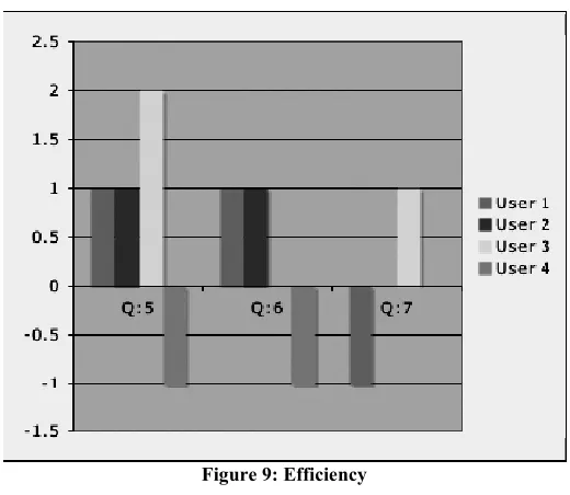
Concerning the effectiveness of the mechanism, user 1 and 4 (engineers) are less satisfied than user 2 and 3. However, regarding the efficiency aspect, user 4 remains unsatisfied while his/her colleague has a different point of view.
Figure 9: Efficiency CONCLUSIONS TUI design as a Fitness problem
In this paper we adapted the original fitness problem proposed by Alexander (1964) to the design of TUI’s. This approach allows the designer to work simultaneously with the potentially conflicting hardware and physical ergonomic requirements of the tangible interface design. Here we reduce the complexity of the hardware and physical ergonomic requirements and finally identify a component level fitness-of-use between the hardware and the physical-ergonomics. This component level fitness is a form of requirement specification that may be used by the designer to identify the final form of the tangible interface for the given application.
Guidelines for TUI design
Our analysis of the conflicting requirements based on the fitness approach led to eight specific questions that might be used as guidelines for the design of TUI’s. Figure 1 summarizes our eight questions. The first four questions define the space within which the desired tangible interface is sought. The next two questions orient the tangible interaction based on Ullmer’s framework and finally, we layout the details of initiating and terminating the interaction using Bellotti’s ideas. It might not always be easy to answer these questions, but in our opinion these questions can lead the designer to think about aspects of the design they may otherwise neglected.
easy to design. Therefore, the use of this mechanism will help to accurately identify the problems and next location in workflow while providing the kind of expertise needed in order to solve them. Above all, this mechanism can provide a means to collaborate and communicate TUI design between scientists, designers and engineers without hindering their ideas and /or vision.
FUTURE WORK
In the future we intend to extend the checklist into a set of heuristics and then attempt to chart the cost-benefit tradeoffs at a component level. This chart can then lay the foundations for a predictive model for tangible interface design, in the lines of GOMS (Card et al., 1983) and Critical Path Analysis (Baber and Mellor, 2001). Such models permit early evaluation of designs (prior to building and testing of prototypes) by employing predictive models of user performance to evaluate competing designs.
REFERENCES
Alexander C. 1964. Notes on the synthesis of form, Harvard University Press, Cambridge, Massachusetts.
Baber, C.; Mellor, B., (2001), “Using critical path analysis to model multimodal human-computer interaction”, in International Journal of Human Computer Studies, 2001 54(1), 613-636. Bellotti, V., Back, M., Edwards, W. K., Grinter, R. E., Henderson, A. and Lopes, C. (2002),
“Making Sense of Sensing Systems: Five Questions for Designers and Researchers”, in Proceedings of CHI'02 Conference on Human Factors in Computing Systems, 415–422. ACM Press.
Bernsen, N. O. (2001), “Multimodality in language and speech systems - from theory to design support tool”, Chapter in Granström, B. (Ed.): Multimodality in Language and Speech Systems. Dordrecht: Kluwer Academic Publishers.
Card, S; Thomas M and Allen N (1983), “The Psychology of Human-Computer Interaction”, Hillsdale, New Jersey: Lawrence Erlbaum
Carroll JM, Rosson MB, Chin Jr George, Koenemann Jürgen (1998) "Requirements development in scenario-based design", in IEEE Transactions on Software Engineering, 1156-1170. Dourish P. (2001) Where the Action is: The Foundation for Embodied Interaction, Cambridge,
MIT Press.
Fitzmaurice, G. W., Ishii, H., & Buxton, W. A. S. (1995) “Bricks: laying the foundations for graspable user interfaces”, in Proceedings of the CHI’95 conference on Human factors in computing systems, 442–449. ACM Press.
Frohlich, B. and Plate, J. (2000), “The Cubic Mouse: A New Device for Three-Dimensional Input”, in Proceedings of CHI'00 Conference on Human Factors in Computing Systems, 526 – 531. ACM Press.
Gorbet, Matthew G, Orth M, Ishii H. (1998), “Triangles: Tangible Interface for Manipulation and Exploration of Digital Information Topography”, in the Proceedings of CHI '98 conference on Human Factors in Computing Systems, 1-8. ACM Press.
Greenberg, S. and Fitchett, C. (2001), “Phidgets: Easy Development of Physical Interfaces through Physical Widgets”, Proceedings of the UIST 2001 14th Annual ACM Symposium on User Interface Software and Technology, 209-218, ACM Press.
Kaptelimin V., Nardi B, Macaulay C. (1999), “Methods & Tools: The activity checklist: A tool for representing the “space” of context”, Interaction, July-August 1999, 27-39. Quote from the book: Leont’ev, A. N. Problems of the Development of Mind. Progress, Moscow, 1981. Kimiko, R., Marti S., and Ishii H. (2004), “I/O Brush: Drawing with Everyday Objects as Ink”,
Proceedings of CHI'04 Conference on Human Factors in Computing Systems, 452-458. ACM Press.
Rauterberg, M., Fjeld, M., Krueger, H., Bichsel, M., Leonhard, U. and Meier, M. (1997), “BUILD-IT: A Computer Vision-based Interaction Technique for a Planning Tool”, in Proceedings of HCI '97, 303-314. Springer
Rekimoto, J., Ullmer, B., & Oba, H. (2001), “ Datatiles: a modular platform for mixed physical and graphical interactions”, in Proceedings of the CHI’01 Conference on Human factors in Computing Systems, 269–276. ACM Press.
Ullmer, B., Ishii, H., and Glas, D (1998). “ MediaBlocks: Physical Containers, Transports, and Controls for Online Media”, in Proceedings of SIGGRAPH'98 conference on Computer Graphics, July 19-24, 1998, 379-386. ACM Press.
Ullmer, B., & Ishii, H. (1997), “The Metadesk: models and prototypes for tangible user interfaces”, in Proceedings of the UIST 1997 10th Annual ACM Symposium on User Interface Software and Technology, 223–232. ACM Press.
Ullmer, B. and Ishii, H. (2000), “Emerging Frameworks for Tangible User Interfaces”, IBM Systems Journal, 393(3) 915-931.
Ullmer, B. (2002), “Tangible Interfaces for Manipulating Aggregates of Digital Information”, Unpublished doctoral dissertation, Massachusetts Institute of Technology.
APPENDIX
This section tabulates how some of the existing systems address the fitness problem. We’ve tried to define the fitness desired and orient the nature of the fitness. The last two questions relating to the component level fitness are not discussed here since they relate to the designers idea of the solution and different designers might provide different component level fitness.
1.1 What should the user experienc e? What are the human tasks? 1.2 What would the artefact represent and control? What are the conventi ons? What is the nature of the interactio n for each sub-task? Does the sub-task need to any
relational interaction?
1.3
MediaBlock s (Ullmer et al, 1998) 1.4 -Record and carry data without using computer interface. -Display data -Putting info into a container. -Carry the information. -Sequence the information. Represent: Container Control: Media’ sequence Ergonomic: -Easy to carry Electro-Mechanical: 1.5 -Connect to several devices. 1.6 Media Sequences Device (Discrete Interacti on) 1.7 1.8 1.9 Sub-tasks performed in combination with: Video Camera Video Display Printer Digital white board. 1.10 Triangles Module (Gorbet et al. 1998) Manipulate, connect and combine information chunk. -Grasp and manipulate digital information.
Build 2 and 3D shapes Represent: Chunk of information to be connected and assembled. Control: The arrangement of the information by triggering events in the digital space based on a user manipulation of a physical element.
Ergonomic: Must allow the construction of 2 and 3D shapes. Electro-Mechanical: Easy to connect and disconnect. Must produce the manipulated information in real time
Built-it System (Rauterberg
et al. 1997)
Planning a plan layout and simultaneously
the result in real time.
Navigating Positioning
Represent: The object within the space. Control: Positioning and rotating the object.
Ergonomic: Simultaneou s 2D and 3D view. Electro- Mechanical: Displaying Positioning 3DOF
The
information is displayed in real time. (Continuous interaction)
Printing
1.12 Table 1 COPYRIGHT