COSMIC FPA CALCULATOR FOR MOBILE APPLICATION
DEVELOPMENT COST BASED ON UNITY3D GAME
ENGINE
Nur Atiqah Sia Abdullah, Nur Ida Aniza Rusli
Faculty of Computer and Mathematical Sciences, Universiti Teknologi MARA 40450 Shah Alam, Selangor, Malaysia
[email protected], [email protected]
Abstract
The emergence technology and popularity of mobile game application has led to higher demands in producing more colorful game environment, interactive design and selecting targeted platforms. To fulfil these requirements, mobile game engine; a framework to create mobile game application should provide greater complexity and parameters to be added in the mobile game properties. Thus makes the effort costing of mobile application development difficult to be estimate accurately. Therefore, these mobile game requirements is a new conceptual of software that still need to be tested properly to existing estimation models as these estimation models are invented before the emergence of mobile application requirements. Hence, the motivation is to adapt COSMIC Functional Size Measurement (COSMIC FSM) for sizing the mobile game application development as it is one of the estimation models suitable to sizing embedded software and real-time system. This research use Unity3D game engine as the platform to represent the mobile game requirements. These requirements are illustrated in the form of component diagrams and class diagrams to order to maintain and control the behavior of Unity3D features. The functional processes from component diagrams and class diagrams are captured to be used later in the sizing process using COSMIC FSM from the mapping between UML based-COSMIC FSM rules and measurement. A tool, COSMIC FPA Calculator for Mobile Application is developed to demonstrate the COSMIC FSM counting process for mobile game application costing.
Keywords: Software Measurement, Software Effort Estimation, COSMIC Functional Size Measurement, UML, Mobile game application
1.
Introduction
In general, software cost estimation involves the measurement of project properties such as software, hardware and travel costing. However, most of estimation of software costing is dominantly using effort estimation where it can be converted directly to the project duration and cost together (Leung et al., 2002). Effort cost estimation process the number of outcome produces and divides with number person per months required to the development of the software project. These two effort costing component usually can be performed in the term of size-related metric or function related metric to measure.
This function-related metric has successful in estimates the software size from the software requirements or business models (Lind et al., 2011; Uemura et al., 1999). Functional Size Measurement (FSM) is one of promising for measuring functionality delivered system. The FSM method was originally proposed by Albrecht Function Point to size the project from the five elements of input, output, inquiries, internal and external files.
Going through the evolution and to improve Albrecht Function Point method, FSM has provide users with several FSM technique such as International Function Point User’s Group of Function Point Analysis (ISO/IEC 20926, 2003), Mk II Method of Function Point Analysis (ISO/IEC 20968, 2002), NESMA Function Point Analysis (ISO/IEC 24570), COSMIC Functional Size Measurement Method (ISO/IEC 19761, 2003) and FiSMA Functional Size Measurement (ISO/IEC 29881, 2008) to cater different scenario of software development (Meli et al., 1999).
This research adapts COSMIC FSM for sizing the mobile game application is one of the evolutions in FPA that successfully estimate for embedded software and real-time system (Soubra et al., 2011; Lind et al., 2009). The rules and measurement of COSMIC FSM are utilized to be mapped with this new gaming context characteristics and requirements.
Gaming is one of entertainment areas that are increasing in popularity. With the emerging market, game platform has witnessed the game transformation from the game machines, video games, PC games to mobile application (Herman et al., 2002). The emerging innovations of 3D technology along with wider, faster and more mobile internet accessibility are expected to give a strong gaming competition in the market. The process of game development requires developers to have a good idea of what component that should be used for the development and specific tasks should be performed for user satisfaction. Since game development involves a long code of programs, the game engine is very useful to organize a group of program code that perform the task according to the requirement. The game engine is a system designed for the creation and development of the game. It is able to simplify the design process and handles or maintains the whole process of development of the game application (Gregory et al., 2009; Abdullah et al.,2013; Abdullah et al., 2014).
There are many game engines that are available in the market. This study focused on five game engines as the platform for the mobile game application development. Unity 3D, ShiVa 3D, Irrlicht 3D Engine, Reality Factory and Panda3D were chosen to be compared and evaluated. These game engines are chosen because of open source and provide sufficient features of the game engine.
This paper is structured as follows: Section 2 reviews the mobile game engine; Section 3 contains a research framework for this research; Section 4 discusses the UML presentation of Unity3D; Section 5 shows the mapping process between UML modelling and COSMIC FSM; Section 6 summarizes the COSMIC FSM evaluation for Unity3D. Finally Section 7 describes some conclusion.
2.
Methods
Unity3D is an ecosystem game development developed by Unity Technologies (Unity Technologies, 2015). This game engine provides a service to import 2D and 3D game content to the game scene with the various optional features to use such as scripting using Java programming language, tools and 3D editors especially for Windows and Mac operating system.
ShiVa Engine is a game engine that supports more than 21 features to games in platforms such as Windows, Linux and Mac OS (ShiVa Engine, 2015). Developed by StoneTrip, this game engine provides features such as animation editor, ambience editor and material editor to be implemented in devices such as PCs, Mac and Mobile Phone. Implemented in C++ programming language; ShiVa Engine also compatible using plugin such as Cinema 4D and Maya Blender for animation and graphical design. Irrlicht Engine is a 3D game engine that designed by Nikolaus Gebhardt (Irrlicht Engine, 2015). Irrlicht Engine is written in C++ and VB.NET provides the elements like scene editor, lightmap generator and indoor/outdoor technology to be added in the game. Irrlicht Engine also provides irrEdit and GUI editor to customize the game environment.
Next is Reality Factory. Reality Factory simplifies the creation of the game application by using C++ programming language (Reality Factory, 2015). Developed by Gekido Design Group, this game engine uses Genesis3D to render the real-time game environment with advanced features such as pathpoint engine, camera controls and physic/dynamic shadows.Lastly, Reality Factory is a game engine that renders the game environment in Python and C++ programming language (Panda 3D, 2015). This game engine offers features such as native DirectGUI system, 3D Studio Max and Maya model through plug-in and also OpenAL audio engine for game developers. The features of mentioned game engines will be evaluated using Petridis Methodology in the next section.
A. Petridis Methodology for Comparing Game Engine
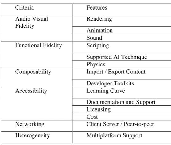
This section describes the detail process of selecting game engine which can be used as a benchmark for the requirement of mobile game application. The selection of game engine is carried out based on the comparison criteria proposed by Petridis methodology. The six criteria in this methodology; fidelity, composability, accessibility, networking and heterogeneity as shown in Table 1 reflects the architecture of the game engine and manage to provide adequate information to be used in evaluation of game engine.
The concept of fidelity is defined as the bases to visualize the knowledge learnt in the real world and to be transformed to the game environment. As the representation of features such as narrative, depth of visualization and characters’ behaviour, Petridis et al., (2010) divides this fidelity into audio-visual fidelity and function fidelity to make a clear distinction of features to be used in the illustration of the game. Audio-visual fidelity includes features such as rendering, animation, sound and effect meanwhile functional fidelity takes the feature such as scripting, AI technique and physics to be grouped together.
Table 1. Criteria for Comparing Game Engines.
Criteria Features
Audio Visual Fidelity
Rendering Animation Sound Functional Fidelity Scripting
Supported AI Technique Physics
Composability Import / Export Content Developer Toolkits Accessibility Learning Curve
Documentation and Support Licensing
Cost
Networking Client Server / Peer-to-peer Heterogeneity Multiplatform Support
Meanwhile, networking is used to support the game application in a larger scale by enable game application to have multiplayer connected and interacts through servers. Client server and peer-to-peer manage to increase the popularity and provide a long term playing game. Lastly heterogeneity is concerns on the element to deploy the game on specific devices or software. This enables the game to be released in application such as GPS, simulator or mobile phones.
B. Comparison of Selected Game Engines
As the objective to estimate the functionality of mobile game, Audio Visual, Functional Fidelity and Networking are going to be described in detail for the comparison process. These chosen criteria are appropriate features in the game engine architecture can be mapped to COSMIC rules and measurement. Composability, Accessibility, and Heterogeneity are excluded as these criteria do not have the required functionality to estimates. This paper adapts Petridis’s methodology to compare Unity3D, ShiVa Engine, Irrlicht3D Engine, Reality Factory and Panda3D. It is shown in Table 2 and Table 3.
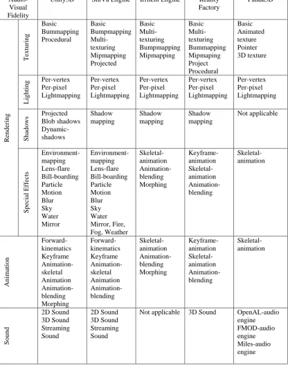
Table 2 shows Unity3D, ShiVa Engine and Reality Factory provide various features for audio-visual fidelity. These three game engines support elements such as texturing, lighting, shadows, special effect, animation and sounds. This assessment shows that Unity3D, ShiVa Engine and Reality Factory are the game engines that are able to support the technologies used for computer graphics.
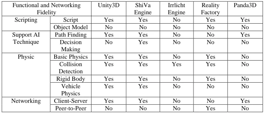
From the three criteria, the Unity3D and ShiVA game engine offered similar features in terms of functionality, networking and audio-visual fidelity. This two game engine will be a benchmark of the game engine to be used for further estimation using COSMIC FSM as both game engines has sufficient features used by common mobile application and more comprehensive to be used in a case study for mobile application development estimation. Moreover, both of game engines also support multiple platforms including iOS, Windows Phone and Android.
Table 2. Comparison of Game Engines in Audio-Visual Fidelity.
Audio-Visual Fidelity
Unity3D ShiVa Engine Irrlicht Engine Reality Factory Panda3D R en d er in g Te x tu rin g Basic Bummapping Procedural Basic Bumpmapping Multi-texturing Mipmapping Projected Basic Multi-texturing Bumpmapping Mipmapping Basic Multi-texturing Bummapping Mipmaping Project Procedural Basic Animated texture Pointer 3D texture L ig h tin g Per-vertex Per-pixel Lightmapping Per-vertex Per-pixel Lightmapping Per-vertex Per-pixel Lightmapping Per-vertex Per-pixel Lightmapping Per-vertex Per-pixel Lightmapping Sh ad o ws Projected Blob shadows Dynamic-shadows Shadow mapping Shadow mapping Shadow mapping Not applicable Sp ec ial E ff ec ts Environment-mapping Lens-flare Bill-boarding Particle Motion Blur Sky Water Mirror Environment-mapping Lens-flare Bill-boarding Particle Motion Blur Sky Water Mirror, Fire, Fog, Weather Skeletal-animation Animation-blending Morphing Keyframe-animation Skeletal-animation Animation-blending Skeletal-animation An im atio n Forward-kinematics Keyframe Animation-skeletal Animation Animation-blending Morphing Forward-kinematics Keyframe Animation-skeletal Animation Animation-blending Skeletal-animation Animation-blending Morphing Keyframe-animation Skeletal-animation Animation-blending Skeletal-animation So u n d 2D Sound 3D Sound Streaming Sound 2D Sound 3D Sound Streaming Sound
Table 3. Comparison of Game Engines in Functional Fidelity and Networking Fidelity. Functional and Networking
Fidelity
Unity3D ShiVa Engine
Irrlicht Engine
Reality Factory
Panda3D
Scripting Script Yes Yes No Yes Yes
Object Model No No No No No
Support AI Technique
Path Finding Yes Yes No No Yes
Decision Making
No Yes No No No
Physic Basic Physics Yes Yes No Yes No
Collision Detection
Yes Yes Yes Yes No
Rigid Body Yes Yes No Yes No
Vehicle Physics
Yes Yes No No No
Networking Client-Server Yes Yes No No Yes
Peer-to-Peer No No No Yes No
However, Unity3D is chosen for further estimation because it is one of the most widely referred game engines in most of the research and mobile development. Unity3D also has released 80 mobile games compared to ShiVa game engine has released 28 mobile game according DevMaster (DevMaster, 2015) and ModDB (ModDB, 2015) game engine databases. Unity3D also has a large community and provides many tutorials to be learned.
3.
Research Framework
This section describes the conceptual framework of this research. The detail procedure and method to collect data is shown in Figure 1. The research framework is consists five phases; preliminary study, analysis of literature, UML modelling and mapping, system design and implementation, and also finding phase manage to help the structural process for developing the estimation tool for mobile game application. This framework is a good approach for identify the research objectives, purposes and data collection to be used in the measurement. The detail steps for each stage for Unity3D UML-COSMIC FSM are describes in following section.
a. Preliminary Phase
The work begins with collecting information from journals and articles to allow this search to have strong foundation in the domain area. This phase also performs the analysis of software cost estimation, functional size measurement and mobile game application development and framework to enable this study associate these concept for further research.
b. Systematic Review
Phase
Activity
Outcome
Figure1. Research framework
1. System objectives 2. Hardware and software
requirements
3. UML model for the tool
4. Testing with various UML game model SDLC Waterfall Methodology
Requirement
Analysis
System Design
Implementation and Testing
System Design and Development
1. Component diagram and class diagram of Unity3D 2. Mapping table of
COSMIC-UML 3. Mapping tables of
COSMIC mobile game 4. Data movement table 1. UML representation of Unity 3D
game engine
2. Mapping COSMIC concept and UML
Identification of COSMIC concept with mobile game
Identification of functional process and data movement
Calculation of COSMIC function point
UML Modelling and
Mapping
1. Rules and calculation for COSMIC FSM
2. Comparison table of Unity3D, ShiVa3D, Irrlicht3D Engine, Reality Factory and Panda3D
Detail characteristics of: 1. Detail of COSMIC FSM
measurements, steps and rules with COSMIC-UML 2. Game engine architecture Systematic
Review
1. Research problem 2. Research objectives 3. Research questions 4. Scope of study Review of:
1. Software metrics
2. Software metrics for mobile application
3. Software Cost Estimation 4. Function Point Analysis (FPA) 5. Mobile game application 6. Game engine
Theoretical Study
COSMIC FPA Calculator for Mobile App
c. UML Representation and Mapping
This phase is composed of UML representation of the Unity3D game engine. The UML model of Unity3D is constructed to presenting the assets and the flow of data or components in Unity3D. The mapping rules between COSMIC concept and UML are finalized to be used as a guideline for calculating COSMIC function point (CFP) value for mobile application. This phase continues with the process of obtaining the CFP value of Unity3D by mapping the UML modelling of Unity3D game engine to COSMIC rules. Mapping COSMIC rules and UML model of the Unity3D game engine will determine the elements that will distribute to COSMIC Entry, Read, Write or Exit data movements before it can be aggregated to numbers.
d. Systematic Design and Development
This phase involves the process of gathering the requirements to develop a calculator for mobile application using COSMIC function point. The components are identified to be used as the medium to implement the software measurement. The components required for the development of calculator are listed below.
- Checkbox. This component allow user to tick several inputs data entry such as camera,
audio and particle system to process at a time.
- Tabbed panes. The calculation provides 28 checkboxes to represent Unity3D
components. Tabbed panes is suitable for organize these 28 checkboxes by splitting these checkboxes into two tabs. Although it is distributed in two tabs, but the function of tabbed panes allows the values of checkboxes pointed in a single reference.
- Text fields. Text fields allow user to continue the costing process by insert the amount of
duration to develop the project and salary per one programmer.
- Table. Table is used to display the detail information from the data entry, including the
message and data movements of the mobile game component.
The design phase is illustrated using component diagrams and class diagram to represent the data of the calculator. From the UML modelling, the calculator allows the activities such as selection of data entry, COSMIC function point calculation, and effort costing for the mobile game application project.
e. Findings
The outcome of the study explains the elements in the UML representation of Unity3D game engine able to capture the functional process of COSMIC FSM and categorized into the COSMIC data elements; Read, Write, Entry or Exit for the sizing process. The mapping process allows this research to obtain the function point based on the UML concept and COSMIC FSM rules and measurement.
4.
The UML Modelling of Unity3D
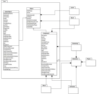
This section describes the function point calculation process based on Unity3D game engine environment. The process begins with the illustration of UML model of Unity3D to represent the requirements for mobile game application development. This reverse engineering process leads to creation of UML modelling based on Unity3D documentation. This UML modelling divides into several groups of component and classes.
The elements in the GameObject and Components are inherited from the Object class. The element in Object associates with classes in other components. This Object class is crucial to create, use or destroy the model for current scene.
Figure 2. Core component diagram in Unity3D
Figure 3. Behaviour component diagram in Unity3D
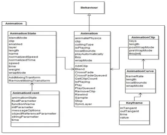
Animation component consists of Animation, Animation State, AnimationEvent, AnimationClip, AnimationCurve and Keyframe class diagrams. Allow the modification of game speed, time and scripting to play the game animation, the detail Animation component diagram in Unity3D is shown in Figure 4.
Figure 4. Animation component diagram in Unity3D
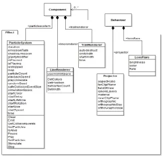
Figure 5. Physic component diagram in Unity3D
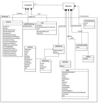
Figure 6. Rendering component diagram in Unity3D
Figure 7. Mesh component diagram in Unity3D
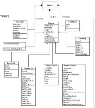
Figure 9. Asset component diagram in Unity3D
The following section presents the mapping procedure between UML modelling of Unity3D and COSMIC FSM. The adaption of COSMIC FSM in UML modelling is crucial for the identification of functional process and also the data movement which these element capable to be used later in the estimation process.
5.
UML Modelling and COSMIC FSM Mapping
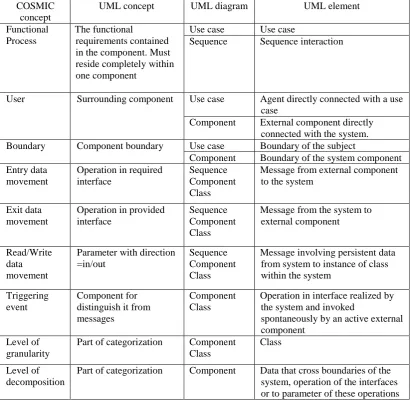
Table 4. Mapping rules between COSMIC concept and the UML (Source: Lavazza et al., 2009)
COSMIC concept
UML concept UML diagram UML element Functional
Process
The functional
requirements contained in the component. Must reside completely within one component
Use case Use case
Sequence Sequence interaction
User Surrounding component Use case Agent directly connected with a use case
Component External component directly connected with the system. Boundary Component boundary Use case Boundary of the subject
Component Boundary of the system component Entry data
movement
Operation in required interface
Sequence Component Class
Message from external component to the system
Exit data movement
Operation in provided interface
Sequence Component Class
Message from the system to external component
Read/Write data movement
Parameter with direction =in/out
Sequence Component Class
Message involving persistent data from system to instance of class within the system
Triggering event
Component for distinguish it from messages
Component Class
Operation in interface realized by the system and invoked
spontaneously by an active external component
Level of granularity
Part of categorization Component Class
Class
Level of decomposition
Part of categorization Component Data that cross boundaries of the system, operation of the interfaces or to parameter of these operations
COSMIC FSM categorized the data movements into entry, exit, read or write from the operations in component diagram and class diagram. The identification and categorization of data movement (entry, exit, read or write) in each functional process is according the message contained in the function. Entry data movement allows the process of bringing the message from external resources to the system. It is opposites to exit data movement where the message from the data in the system to the external component. Read or write data movement is identified by the message involving persistent data from system to instance of class within the system. Lastly the triggering events also are performed for this process.
6.
COSMIC FSM Measurement for Unity3D
query message (as read data movement); build connection message (write data movement); a request message (as entry data movement) or response to the message (exit data movement).
The data movement is illustrated in Table 5 consists of data movement and size of transaction for Core component, Behaviour component, Physic component, Rendering component, Animation component, Mesh component, Effect component and Asset component respectively.
Table 5: Data Movement and Size Of Transaction For Unity3D
Component Process R W E X CFP
Core Object 2 2 2 2 8
Component 3 1 2 1 7
GameObject 5 2 7 1 15
Behaviour Behaviour 0 0 1 1 2
Mono Behaviour
0 1 3 3 7
Physic RigidBody 5 2 9 1 17
Collider 0 2 0 0 2
Character Controller
0 2 0 0 2
Wheel Collider
1 0 0 0 1
Physics 3 8 0 2 13
Rendering Camera 5 9 0 4 18
LOD 1 1 0 0 2
GUIElement 2 0 0 0 2
GUILayer 1 0 0 0 1
Animation Animation State
0 0 1 1 2
Animation 3 5 4 1 13
Mesh Mesh 5 5 1 0 11
Skinned Mesh
0 1 0 0 1
Effect Particle System
4 2 4 0 10
Line Renderer
0 4 0 0 4
Asset AudioClip 1 1 0 0 2
Procedural Texture
1 0 0 0 1
Texture3D 2 1 0 0 3
Texture2D 7 7 0 0 14
Movie Texture
0 3 0 0 3
Render Texture
1 3 1 1 6
CubeMap 3 3 0 0 6
Texture 2 0 0 0 2
Total CFP 175
represents the FindObjectOfType from the Object component. One Write data movement is estimated from the MonoBehaviour data group represents the IsInvoking function in Behaviour component. The Exit and Entry data movement is identified from the RenderTexture data group represent as DiscardContents and Create functions respectively.
The Unity3D game engine is estimated have 175 COSMIC Function Point CFP by adding up all the number of Entry, Exit, and Read and Write data movements. The following contains the procedure of mapping the COSMIC rules and UML concept for Unity3D:
• Step 1 involves the process of capturing the layers embedded in the software. The
illustration of requirement processes are only considers the software layer as one layer only. All functional requirements are assumed to be on the same level.
• Step 2 provides the identification of the boundary underlying in the software. The
measurement towards this software boundary is from the interaction among component diagrams in the Unity3D. The component diagrams serves as the maintenance of the class diagrams that are embedded in the components.
• Step 3 is the process to capture the functional process in Unity3D from the operations
and interactions between class diagrams.
• Step 4 is the process of the finding the data group from the requirements. This paper
by default assumes all functions in the same class diagram as one data group
A. Prototype
This section presents the estimation tool for mobile game application. The values of components collected from the Unity3D game engine are aggregated into number as a result of the mapping process between UML modelling and COSMIC FSM rules and measurement. Mobile game components and its functional values are then structured into this estimation tool.
This estimation tool provides a set of package entry to allow users to select component for the mobile game application development. The Unity3D components are listed in two packages. Fig 10 shows the list of components including Core, Behaviour, Physic and Rendering. Meanwhile Animation, Mesh, Effect and Asset component are placed in package two in Fig 11. The overall effort estimation of mobile game application development can be further processed based the total function point obtained from the package entry.
Figure 12. Effort Estimation Calculation
When the entire components have been specified, the tool will computes the total function point in COSMIC function point. The total cost of software project can be obtained when user enter duration (per month) to complete the project and salary (per month) for one programmer, as illustrated in Figure 12. The tool effectively supports the estimation for mobile game application by using function point approach specifically in COSMIC function point from the utilization of assets in Unity3D.
7.
Conclusion
This paper presented COSMIC FSM for sizing the mobile game development. Creation of mobile game requires complex requirements. Therefore, adaption of game engine architecture to represent the requirement of mobile game is acceptable to sizing the effort estimation of mobile game application using COSMIC FSM rules and measurement. Selection of Unity3D through the evaluation of game engine methodology proposed by Petridis’s is important to be use as benchmark for mobile game design. Represented in UML modelling, Unity3D functions are controlled in the component and class diagrams context in order to maintain the performance of each function. The mapping procedure between UML modelling and COSMIC FSM rules is crucial to obtain the COSMIC FSM function point of mobile game application. This paper also demonstrates an estimation tool to help practitioner to calculate the effort estimation of mobile game application using COSMIC FSM.
Acknowledgement
The authors express appreciation to Research Management Institute (RMI) and Faculty of Computer and Mathematical Sciences of Universiti Teknologi MARA for sponsoring this paper.
References
Abdullah, N.A.S., Rusli, N.I.A., & Ibrahim, M.F. (2013). A Case Study in COSMIC Functional Size Measurement: Angry Birds Mobile Application. Proceedings of the IEEE Conference on Open Systems, 139-144.
Abdullah, N. A. S., Rusli, N. I. A., & Ibrahim, M. F. (2014, October). Mobile game size estimation: COSMIC FSM rules, UML mapping model and Unity3D game engine. In Open Systems (ICOS), 2014 IEEE Conference on (pp. 42-47). IEEE.
Implementation Guide for ISO/IEC 19761: 2003).
Retrieved
from
http://www.cosmicon.com/portal/public/COSMIC%20Method%20v3.0.1%20Me
asurement%20Manual.pdf
DevMaster (2015). Retrieved from http://devmaster.net/.
Gregory, J., Lander, J., & Whiting, M. (2009). Game engine architecture. AK Peters.
Herman, L., Horwitz, J., Kent, S., & Miller, S. (2002). The history of video games. Gamespot. Retrieved on February, 7, 2002.
Irrlicht Engine (2015). Retrieved from http://irrlicht.sourceforge.net/.
ISO/IEC 19761. (2003). COSMIC Full Function Points Measurement Manual v.2.2.
ISO/IEC 20926. (2003). Software Engineering – IFPUG 4.1 Unadjusted FSM Method – Counting Practices Manual.
ISO/IEC 20968. (2002). Software engineering - Mk II Function Point Analysis - Counting Practices Manual.
ISO/IEC 24570. (2004). Software Engineering-NESMA Functional Size Measurement Method version 2.1-Definitions and Counting Guidelines for the Application of Function Point Analysis. International Organization for Standardization, Geneva.
ISO/IEC 29881. (2008). Software Engineering—FiSMA Functional Size Measurement Method version 1.1, Int’l Organization for Standardization, 2008.
Lavazza, L., & Del Bianco, V. (2009). A case study in COSMIC functional size
measurement: The rice cooker revisited. In Software Process and Product
Measurement (pp. 101-121). Springer Berlin Heidelberg.
Leung, H., & Fan, Z. (2002). Software cost estimation. Handbook of Software
Engineering, Hong Kong Polytechnic University.
Lind, K., Heldal, R., Harutyunyan, T., & Heimdahl, T. (2011, November). CompSize:
Automated size estimation of embedded software components. In Software
Measurement, 2011 Joint Conference of the 21st Int'l Workshop on and 6th Int'l Conference on Software Process and Product Measurement (IWSM- MENSURA). 86-95. doi: 10.1109/IWSM-MENSURA.2011.49
Meli, R., & Santillo, L. (1999, October). Function point estimation methods: a
comparative overview. In FESMA (Vol. 99, pp. 6-8).
ModDB (2015). Retrieved from http://www.moddb.com/.
Panda3D (2015). Retrieved from http://www.panda3d.org/.
Petridis, P., Dunwell, I., de Freitas, S., & Panzoli, D. (2010, March). An engine selection
methodology for high fidelity serious games. In Games and Virtual Worlds for Serious
Applications (VS-GAMES), 2010 Second International Conference on (pp. 27-34). IEEE.
Soubra, H., Abran, A., Stern, S., & Ramdan-Cherif, A. (2011, November). Design of a Functional Size Measurement Procedure for Real-Time Embedded Software
Requirements Expressed using the Simulink Model. In Software Measurement,
2011 Joint Conference of the 21st Int'l Workshop on and 6th Int'l Conference on Software Process and Product Measurement (IWSM-MENSURA) (pp. 76-85). IEEE.
ShiVa Technologies (2015). ShiVa editor. Retrieved from http://www.stonetrip.com/.
Uemura, T., Kusumoto, S., & Inoue, K. (1999). Function point measurement tool for
UML design specification. In Software Metrics Symposium, 1999. Proceedings. Sixth International (pp. 62-69).