A NEW TAPERED SLOT ANTENNA WITH
SYMMETRICAL AND STABLE RADIATION PATTERN
H.-Y. Xu, H. Zhang, J. Wang, and L.-X. Ma
Missile Institute
Air Force Engineering University Sanyuan, Shaanxi 713800, China
Abstract—An ultra-wideband exponential tapered slot antenna with new geometrical gratings, which is fed by a nonuniform CPW-slotline balun that is essentially important for the ultra-wide band characteristic, has been introduced in this paper. The measurement shows that the frequency band is from 1.7 GHz to over 13 GHz, among which theS11 is below−10 dB except 2.35 GHz around (below −9 dB). The gratings are introduced to make the antenna to perform better radiation characteristics of a comparatively stable, symmetrical pattern and low side lobes over the operating band as well as obviously higher gain and sharper beam width in the low frequency section in comparison with the one without gratings (more than 3 dB at 1.7 GHz).
1. INTRODUCTION
The ultra-wideband (UWB) has been widely used in high resolution UWB radar, ground penetrating radar, precise orientation system, etc. The ultra-wide band (UWB) [1–5] protocol using the spectrum from 3.1 to 10.6 GHz is a new promising technology suitable for high rate communications in small distances, which makes the study on the UWB antennas to be a new great interest. The tapered slot antenna (TSA) have merits of wide band, light weight, small volume, and simplicity of the geometrical configuration, which make TSA to be the great candidate for the unit of antenna array [6]. And its planar geometry allows it to be easily integrated with other planar devices such as filters, SIS and Schottky-diode mixers, or bolometers.
traveling-wave antennas, they have demonstrated broad bandwidth, relatively high gain, and symmetricalE- and H-plane beam patterns [7].
To design a wideband TSA, the feeding network must possess low loss performance over operation frequencies, and should be simple for fabrication. Moreover, because they belong to the class of traveling antennas, the reduction in volume may result in a lessening of antenna performances, especially at the lower frequency sections. However, too large volumes limit the applications. So the balance between the performances and volumes must be found. Because the physical limit of the antenna miniaturization hasn’t been realized [8], it is effective to adopt some steps in antenna configuration, the feed-in form, the material choice except the conductor, etc.
In this paper, an exponential tapered antenna with new geometrical gratings is presented. The results show that the VSWR bandwidth is 1.7 GHz∼13.3 GHz (S11<−10 dB), and among the wide
range of which, the radiation patterns are comparatively symmetrical. Moreover, new configured gratings were corrugated on the two side edges of the antenna to make the radiation patterns inE-andH planes in the whole band more symmetrical as well as improving the radiation efficiency obviously in the low section of the−10 dB bandwidth. 2. DESCRIPTION AND ANALYSIS OF THE ANTENNA
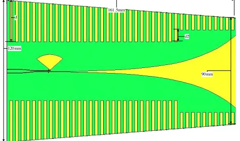
Figure 1 shows the antenna geometry. The antenna is fed by the coplanar waveguide (CPW). In order to meet the ultra-wideband (UWB) demand, a nonuniform CPW-slotline transition [9] is utilized. Thanks to this ultra-wideband balun, the antenna design procedure has become systematic and simplified. The CPW is connected with
90mm 161.5mm
120mm
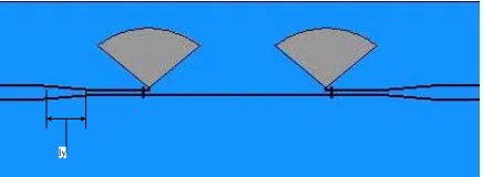
the antenna by the CPW-slotline transition balun. As the detailed shape far from the feed region is unlikely to influence the impedance very much, the starting width of the tapered part need be equal to the width of the slotline of the balun to achieve the matching [10]. The balun is essentially important to get the VSWR bandwidth. So as to get proper size of the balun, the in-phase back-to-back baluns shown in Fig. 2 was simulated and optimized by the HFSS software. The tapered slot radiation part follows the exponential form [11]. One side of the tapered function is
y= 0.6e0.033x
ly
Figure 2. The in-phase back to back CPW-slotline baluns.
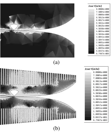
Two sets of new configured gratings [12, 13] were put on the two side edges of the antenna, as a result of which, the radiation patterns inE- andH-planes in the whole band are more symmetrical compared with the one without gratings. And the gain improves obviously in the low frequency section (about 3.3 dB higher at 1.7 GHz). The reason which accounts for the improvement is that the gratings act as dipole antenna array, the length of whose unite unit is much less thanλ/4 in the low frequency section so that it radiates in the endfire direction. And the gratings’ profile is designed to be linear tapered to make the gratings to act as something like the projector of the sharp beam of electric waves. As a result, the gain increases largely at the low edge of the−10 dB bandwidth (about 3.3 dB higher at 1.7 GHz compared with the same exponential antenna without gratings). And the merits of the gratings is validated by the comparison of the current distributions shown in Fig. 3 and radiation patterns in E- and H-plane shown in Fig. 4 respectively.
(a)
(b)
Figure 3. Comparison of the current distributing at 1.7 GHz, (a) without gratings; (b) with gratings.
(a) (b)
Figure 4. Comparison of the radiation pattern at 1.7 GHz between the two antennas (a)E-plane; (b) H-plane.
thickness is [2, 14]
teff/λ0 = (√εr−1)t/λ0
And the λ0 above is the wavelength in vacuum. Although too thick
equivalent thickness increases the gain, it can also make the radiation asymmetric and the efficiency lower. But if it is too thin, the gain will be lessened and the intensity of the substrate insufficient. The antenna in this paper is made on the microwave substrate with its relative permittivity 4.6 and the thickness 1 mm.
The depthdof the gratings should be studied. If the gratings are too deep, more currents will directly flow to the gratings to increase the return loss as well as lessening the radiation efficiency. But if the depth is not enough, the gain doesn’t improve obviously. So the depth
dof the gratings should be optimized. Fig. 5 is the return loss curves of different depth d, which shows the d = 35 mm is best. Likewise, the d2 should be chosen properly for the same reason above. Here,
d2 = 25 mm is the optimum size.
Figure 5. S11 of different d.
Figure 7. Measured VSWR result for the proposed antenna.
Figure 8. Gain comparison versus frequency for the design with and without gratings.
3. SIMULATION AND MEASUREMENT RESULTS
The antenna is fabricated in Fig. 6. The measured S11 is shown
in Fig. 7, from which, it can be seen that the frequency band is from 1.7 GHz to over 13 GHz, among which the S11 is below −10 dB except 1.7 GHz around (below −9 dB). And the gain in the low frequency section increases evidently compared with the antenna without gratings as shown in Fig. 3(a). Fig. 8 is the gain comparison versus frequency between the two antennas.
(a) (b)
(c) (d)
(e) (f)
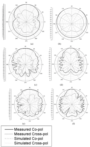
Figure 9. Measured and simulation radiation patterns at different frequencies (a) E-plane at 1.7 GHz; (b) H-plane at 1.7 GHz; (c) E -plane at 8 GHz; (d) H-plane at 8 GHz; (e) E-plane at 12 GHz; (f)
Figure 10. Measurement circumstance.
at different frequencies. It shows the proposed antenna has a comparatively stable and symmetrical pattern and low side lobes through the operating band. And the measurement circumstance is shown in Fig. 10.
4. CONCLUSION
An UWB exponential tapered slot antenna with new geometrical gratings, whose balun is very important for the ultra-wide band characteristic is proposed. The parameter dwhich is in relation with the depth of the gratings is optimized. The measurement shows that the bandwidth is from 1.7 GHz to over 13 GHz, among which the radiation has comparatively symmetrical characteristic and low side lobes in the operating band as well as obviously higher gain (more than 3 dB at 1.7 GHz) and sharper beam width in the low frequency section in comparison with the one without gratings. In addition, it has a comparatively stable gain over the whole operating band. Therefore, the proposed antenna should be useful for broadband wireless communication systems.
REFERENCES
2. Xu, H.-Y., H. Zhang, and J. Wang, “Study on an UWB planar tapered slot antenna with gratings,”Progress In Electromagnetics
Research C, Vol. 1, 87–93, 2008.
3. Elsadek, H. and D. M. Nashaat, “Ultra miniaturized E-shaped PIFA on cheap foam and FR4 substrates,” J. of
Electromagn.Waves and Appl., Vol. 20, No. 3, 291–300, 2006.
4. Khodaei, G. F., J. Nouriniam, and C. Ghobade, “A practical miniaturized U-slot patch antenna with enhanced bandwidth,”
Progress In Electromagnetics Research B, Vol. 3, 47–62, 2008.
5. Shobeyri, M., M. H. Vadjed Samiei, and C. E. Smith, “Compact T ultra-wideband bandpass filter with defected ground structure,”
Progress In Electromagnetics Research Letters, Vol. 4, 25–31, 2008.
6. Wang, S., L. Guo, X. Chen, C. G. Parini, and J. McCormick, “Design of broadband phased array using tapered slot antenna,”
IEEE Proceedings of iWAT2008, 271–274, Chiba, Japan, 2008.
7. Lee, K. F. and W. Chen, Advances in Microstrip and Printed
Antennas, Wiley, 1997.
8. Zhu, Y.-Z. and P. Li, “A novel ultra broadband planar monopoleantenna for UHF,”Chinese Journal of Electron Devices, Vol. 30, No. 2, 804–805, 2007.
9. Ho, C. H., L. Fan, and K. Chang, “New uniplanar coplanar waveg-uide hybrid-ring couplers and magic-Ts,” IEEE Transactions on
Microwave Theory and Techniques, Vol. 42, No. 12, 2440–2448,
Dec. 1994.
10. Yngvesson, K. S., D. H. Schaubert, T. L. Korzeniowski, E. L. Koll-berg, T. Thungren, and J. F. Johansson, “Endfire tapered slot an-tennas on dielectric substrates,”IEEE Transactions on Antennaa
and Propagation, Vol. 33, No. 12, 1392–1400, Dec. 1985.
11. Oraizi, H., “Optimum design of tapered slot antenna profile,”
IEEE Tansactions on Antennas and Propagation, Vol. 51, No. 8,
1987–1995, Aug. 2003.
12. Sugawara, S., Y. Maita, K. Adachi, K. Mori, and K. Mizuno, “A MM-wave tapered slot antenna with improved radiation pattern,”
1997 IEEE MTT-S IMS Dig., 959–962, Denver, 1997.
13. Chen, N. W., C. T. Chuang, and J. W. Shi, “A W-band linear tapered slot antenna on rectangular-grooved silicon substrate,”
IEEE Antenna and Wireless Progation Letter, Vol. 6, 90–92, 2007.