767
Comparison Of Effects Of Spallsize On Mesh
Stiffnessusing Fea
Vipin Badgaiyan
Abstract- Gear is very critical component of transportation. It’s direct impact on traffic safety. Spalling is one of the main failure mechanism of the gear teeth, under the high speed and heavy load. This study focuses on the effect of spalling defects of different sizes on the time varying mesh stiffness. An analytical method is used to quantify the TVMS for healthy and faulty gear. Bending stiffness, Shear stiffness and axial compressive stiffness are taken into account. With increasing spalling size, the time varying mesh stiffness decreases in spalled tooth region. The TVMS is also obtained through finite element analysis for healthy and faulty gear and the results were compared with analytical results.
Keywords: Gear, Time varying mesh stiffness, spalling, bending stiffness, shear stiffness, axial compressive stiffness, finite element analysis. ————————————————————
1
INTRODUCTION
The gear as a important machine component widely used in industries. The dynamic behavior of gear transmissions is sensitive to operating conditions like excessive applied load, insufficient lubrication, manufacturing errors or installation problems, this can cause removal or plastic deformation of contacting tooth surfaces such as spalling. [1] Spalling is the most common type of surface fatigue failure. Spalling is a defect which is produced by high surface stresses and high sliding velocities between in teeth contact. In the initial stage of spalling cracks appear in the tooth surface and spread in the direction of sliding as shown in fig.1 [2]. Due to the spalling defect, time varying mesh stiffness changes and has a greater influence on gear vibration [4]. Ma [5] developed an analytical model by considering the effect of extended tooth contact, tooth spalling defect, fillet foundation, contact stiffness, and double tooth engagement. Yunxia chen,Yi Jin, et al [6], by studying the distribution of meshing force in meshing process, a torque was found When the teeth in the spalling region, based on the potential energy method, a torsional stiffness is established by considering the torque, with the increase of spalling width, the TVMS decreases when the teeth are engaged in spalling region. Chari et al. [3] presented an analytical method to evaluate the mesh stiffness of a pair of external – external gears and modeled the crack as a straight line starting from the root circle. T.Eritenel, R.G. parker,[7] When a pair of spur gear comes in contact, during meshing it’s contact ratio and mesh position changes and this leads to the variation of gear mesh stiffness. Variation of gear mesh stiffness is the main cause of vibration in the gear. In this paper, we use External-External gears to denote meshing gear pair in one stage spur gear system. The mesh stiffness is analytically evaluated using, contact, bending, shear and axial compressive energy for healthy gear pinion model. Further, a spall is created on the gear and mesh stiffness is analytically evaluated for faulty gear pinion model. The gear mesh stiffness is also obtained by finite element analysis for healthy and faulty gear through ansys software.
Fig. 1 Spalling defect in gear teeth [6]
2
METHODOLOGY
In this study time varying mesh stiffness is calculated for healthy and faulty gear, for this gear tooth is assumed to be as cantilever beam model. It is also assumed that spalling defect is located in the mid face of the tooth and shape of spalling is rectangular. The shape of spalling can be expressed (spalling length)L × (spalling width) l × (spalling depth) h . [6]
Fig. 2 The shape of spalling is symmetrical about the mid face of tooth [6]
_______________________
768 The cross section of gear tooth is as shown in fig. 3 spalling
is located near the pitch circle.
Fig. 3 The cross section of gear tooth [6]
Gear tooth is divided into three segments ie AD, DC and CB. A is engagement point, B is disengagement point, D is spalling starting point and C is spalling end point. x x x , x are the values of distance of points A, B, C and D which has been calculated from reference point A. And x is the x value of the time varying contact point.
The area of region AD, DC, and CB can be expressed as-
A = 2y lx < x < x
A = 2y l-h x < x < x ---(1) A = 2y lx < x < x Wherey ,y ,y represents values of the gear tooth contour line with respect to axis of gear teeth in different regions. Moment of inertia of regions AD, DC, and CB can be expressed as-
I =2
3y l x < x < x
I = y l − [ h l + (y − )lh ] x < x < x (2)
I =23y lx < x < x
During the meshing, when teeth contact force F is transmitted from one teeth to another teeth along the line of action as shown in fig4. This force F is having two components in horizontal and vertical directions that are Tangential force F and radial force F = F sin α
--- (3) F = F cos α --- (4)
Bending moment of regions AD, DC and CB can be expressed as-
M = F (x − x ) − F y x < x < x M = F (x − x ) − F y x < x < x -- (5) M = F (x − x ) − F y x < x < x
Potential energy method is applied for finding the bending, shear, and axial compressive energy.
Bending energy- Bending energy U of gear tooth region AD, DC and BC can be expressed as
∫ M
2EI dx x < x < x
∫ dx + ∫ dx x < x < x (6)
∫ dx + ∫ dx + ∫ dx xc< x < x Shear energy- Shear energy U of gear tooth region AD, DC and BC can be expressed as
∫ 1.2F
2GA dx x < x < x ∫ . dx + ∫ . dx x < x < x (7)
∫ . dx + ∫ . dx +∫ . dx x < x < x
Axial compressive energy- Axial compressive energyU of gear tooth region AD, DC and BC can be expressed as
∫ F
2EA dx x < x < x ∫ dx + ∫ dx x < x < x (8)
∫ dx + ∫ dx +∫ dx x < x < x Bending stiffness- bending stiffness of gear tooth can be expressed as
K = ---(9) Shear stiffness- Shear stiffness of gear tooth can be expressed as-
K = ---(10) Axial compressive stiffness- Axial compressive stiffness of gear tooth can be expressed as-
K = ---(11)
Contact stiffness- The Hertzian contact stiffness is a constant value along the line of action it is independent of contact position and expressed for healthy gear as-
K = ( )---(12)
The Hertzian Contact stiffness for faulty gear can be expressed as –
K = ( ( ))---(13) Where E, L, μ represents young’s modulus, tooth contact width and Poisson’s ratio respectively.
The total equivalent mesh stiffness of single tooth pair in meshing can be expressed as-
K =
---(14)
Where subscripts 1and 2 denotes the driving gear and driven gear. The total equivalent mesh stiffness of double teeth pair in meshing can be expressed as
K = ∑
h
---(15)
When gear tooth are meshed and moves one over the other, the contact position changes. Area and moment of inertia also changes. Due to this bending, shear, and axial compressive stiffness need to be considered at every contact position
(1). When meshing teeth contact points are in the region AD ie action force is acting between A and D (−α < −α < −α )
=∫
* ,( ) -+ ( )( ) ,( ) - ( )
dγ --(16)
=∫
( ) ,( )
dγ
---(17) =∫
( ) ,( )
dγ ---(18)
(2). When meshing teeth contact points are in the region
769 =∫
* ,( ) -+ ( )( ) ,( ) - ( )
dγ +
∫ * ,( ) -+ ( )( )
* ,(( ) ]( ) [ { ,( ) - }]+
dγ
---(19)
=∫
( ) ,( )
dγ
+∫ * ,( ) ( ) - +dγ ---(20)
=∫
( ) ,( )
dγ +
∫ * ,( ( ) ) - +dγ ---(21)
(3). When meshing teeth contact points are in the region CB ie action force is acting between C and B (−α < −α <
−α )
=∫
* ,( ) -+ ( )( ) ,( ) - ( )
dγ +
∫ * ,( ) -+ ( )( )
* ,(( ) ]( ) [ { ,( ) - }]+
dγ
+ ∫ * ,( ,( ) ) -+ ( )( - ( ) ) dγ
---(22)
=∫
( ) ,( )
dγ
+∫ * ,( ) ( ) - +dγ +
∫ ,( ( ) ) -dγ ---(23)
=∫
( ) ,( )
dγ +
∫ * ,( ( ) ) - +dγ +∫ ,( ( ) ) -dγ ---(24)
Gear parameters used: Gear parameters used in this study are listed below-
Table 1 Gear parameters
parameters Gear Pinion
Teeth numbers 30 25
Mass (Kg) 0.588 0.46
Base circle radius (mm) 28.19 23.49
Pitch circle radius (mm) 30 25
Addendum radius (mm) 32 27
Dedendum radius (mm) 27.686 22.686
Torque (Nm) 30 25
Tooth width (mm) 20 20
Modulus of elasticity (Gpa) 210 210
Poisson’s ratio 0.3 0.3
Shear modulus( Gpa) 78 78
Shear factor 2 2
Module 2 2
Pressure angle 2 2
3 ANALYTICAL RESULTS
-The effect of different sizes spalling defect in the mid face of gear is investigated. Spall is introduced into the driving gear and the pinion is taken as healthy gear. Length and width of the spall is varied, and the results are compared with the model when both gear and pinion are taken healthy. The parameters used for analytical calculations are given in table 1.
(1). Effect of spalling on TVMS with width variation
The parameters of spall with width variation are given below
in table 2 and the graph of mesh stiffness with time is given in fig.4 From the graph it can be seen that the healthy gear pinion model is having higher value of mesh stiffness but when spall is developed into the gear mesh stiffness values of gear pinion model decreases. As width of the spall increases mesh stiffness values also decreases
Table 2 Variation of Width as a parameter
Fig.4 TVMS of spalled gear under different spalling width
(2). Effect of spalling on TVMS with depth variation-
The parameters of spall with depth variation are given below in table 3 and the graph of mesh stiffness with time is given in fig.5 From the graph it can be seen that the healthy gear pinion model is having higher value of mesh stiffness but when spall is developed into the gear mesh stiffness values of gear pinion model decreases. As depth of the spall increases, mesh stiffness values also decreases.
Table 3 Variation of Depth as a parameter
Depth(mm) Width(mm)
1. 1 1
2. 1 2
3. 1 3
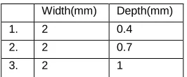
Width(mm) Depth(mm)
1. 2 0.4
2. 2 0.7
770 Fig.5 TVMS of spalled tooth under different spalling depth
4 MODEL DEVELOPMENT-
Spur Gear Model with 25 and 30 numbers of teeth are developed in CATIA V5 R15. The essential elements of the spur gear model is Shown in fig 6. Model contains two pairs of gear meshes each with mass and moment of inertia of gears.
Fig-6 Model development of spur Gear set up
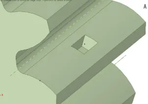
In this analysis rectangular spalling is modelled with six different sizes that might be observed in pracice. The single rectangular tooth spall shown in Fig. 7. The size of spalling considered for analysis as per spall size parameter table 2 and 3.
Fig. 7 Modeled developed different shape of spalling
Finite element analysis
The spur gears are sketched, modelled and assembled in CATIA V5 and saved as an IGES file. The IGES assembly file is imported to the finite element software (ANSYS 19.0) for model analysis. By define contacts, meshing and applying proper boundary conditions and solve, we get the total deformation of the meshing teeth at different contact points of teeth which changes with respect to time and then the time varying mesh stiffness.
Mesh the Object: Meshing of gear tooth is a process of dividing gear tooth into a number of elements so that whenever the load is applied on the gear it distributes the load uniformly.
Fig.8 Meshing
Post processing: after meshing the object, some inputs like fixed support, frictionless support, remote displacement, deformation probe and moments are given.
Fig.9 Post - processing
RESULTS: Deformation value for particular probe comes for gear and pinion. And equivalent stiffness is calculated.
Fig.10 Behaviors of system, total deformation and mesh stiffness
5
FEA RESULTS AND COMPARISON
(1) Comparison of mesh stiffness of faulty gear with healthy gear in analytical calculation when width varies- Time varying mesh stiffness is calculated through analytical calculations for the spall size of parameters given in table 2. And the percentage variation in faulty and healthy gears mesh stiffness is evaluated.
771 gear and faulty gear of spall size depth 1mm and
width 1mm is 4.29%.
b). When spall size of depth 1mm and width 2mm- MaximumVariation in TVMS between healthy gear and faulty gear of spall size depth 1mm and width 2mm is 8.90%.
c). When spall size of depth 1mm and width 3mm- MaximumVariation in TVMS between healthy gear and faulty gear of spall size depth 1mm and width 3mm is 13.89%.
(2) Comparison of mesh stiffness of faulty gear with healthy gear in analytical calculations when depth varies- Time varying mesh stiffness is calculated through analytical calculations for the spall size of parameters given in table 3. And percentage variation in faulty and healthy gears mesh stiffness is evaluated.
a). When spall size of width 2mm and depth 0.4mm -- MaximumVariation in TVMS between healthy gear and faulty gear of spall size width 2mm and depth 0.4mm is 2.09%
b). When spall size of width 2mm and depth 0.7mm- - MaximumVariation in TVMS between healthy gear and faulty gear of spall size width 2mm and depth 0.7mm is 3.16%.
c). When spall size of width 2mm and depth 1mm- - MaximumVariation in TVMS between healthy gear and faulty gear of spall size width 2mm and depth 1mm is 4.28%.
(3)Comparison of mesh stiffness of faulty gear with healthy gear in FEA when width varies- Time varying mesh stiffness is calculated through FEA for the spall size of parameters given in table 2. And the percentage variation in faulty and healthy gears mesh stiffness is evaluated.
a). When spall size of depth 1mm and width 1mm-- MaximumVariation in TVMS between healthy gear and faulty gear of spall size depth 1mm and width 1mm is 2.04%
b). When spall size of depth 1mm and width 2mm-- MaximumVariation in TVMS between healthy gear and faulty gear of spall size depth 1mm and width 2mm is 2.82%
c). When spall size of depth 1mm and width 3mm-- MaximumVariation in TVMS between healthy gear and faulty gear of spall size depth 1mm and width 2mm is 3.52%
(4)Comparison of mesh stiffness of faulty gear with healthy gear in analytical calculations when depth varies- Time varying mesh stiffness is calculated through FEA for the spall size of parameters given in table 3. And percentage variation in faulty and healthy gears mesh stiffness is evaluated.
a). When spall size of width 2mm and depth 0.4mm -- MaximumVariation in TVMS between healthy gear and faulty gear of spall size width 2mm and depth 0.4mm is 2.79%
b). When spall size of width 2mm and depth 0.7mm-- MaximumVariation in TVMS between healthy gear and faulty gear of spall size width 2mm and depth 0.7mm is 2.82%
c). When spall size of width 2mm and depth 1mm--
MaximumVariation in TVMS between healthy gear and faulty gear of spall size width 2mm and depth 1mm is 3.90%
(5)Comparison of mesh stiffen of healthy gear and faulty gear in analytical results and FEA results when width varies-
a). When healthy gear- MaximumVariation in TVMS between healthy of analytical results and FEA results is 10.62%.
b). When spall size of depth 1mm and width 1mm-MaximumVariation in TVMS between analytical results and FEA results for faulty gear of spall size depth 1mm and width 1mm is 9.85%.
c). When spall size of depth 1mm and width 2mm -MaximumVariation in TVMS between analytical results and FEA results for faulty gear of spall size depth 1mm and width 2mm is 10.15%. d). When spall size of depth 1mm and width 3mm
-MaximumVariation in TVMS between analytical results and FEA results for faulty gear of spall size depth 1mm and width 3mm is 10.14%.
(6)Comparison of mesh stiffness of Healthy gear and faulty gear in analytical results and FEA when depth varies-
a). When healthy gear- - MaximumVariation in TVMS between healthy of analytical results and FEA results is 10.62%.
b). When spall size of width 2mm and depth 0.4mm --MaximumVariation in TVMS between analytical results and FEA results for faulty gear of spall size width 2mm and depth 0.4mm is 9.76%. c). When spall size of width 2mm and depth
0.7mm-MaximumVariation in TVMS between analytical results and FEA results for faulty gear of spall size width 2mm and depth 0.7mm is 10.60%. d). When spall size of width 2mm and depth
1mm-MaximumVariation in TVMS between analytical results and FEA results for faulty gear of spall size width 2mm and depth 1mm is 11.18%.
CONCLUSIONS
:772
REFRENCES
[1] Lee, S., Choi, E., Baek, Y., & Lee, C. (2019). Morphology-based Banknote Fitness Determination. IEEE Access, 1– 1.doi:10.1109/access.2019.2917514 [2] Chaari, F., Fakhfakh, T., & Haddar, M. (2009).
Analytical modelling of spur gear tooth crack and influence on gearmesh stiffness. European Journal of Mechanics - A/Solids,2
[3] Ding, Y., & Rieger, N. F. (2003). Spalling formation mechanism for gears. Wear,254(12), 1307-1317. [4] Chaari, F., Fakhfakh, T., & Haddar, M. (2006). Dynamic
analysis of a planetary gear failure caused by tooth pitting and cracking. Journal of Failure Analysis and Prevention,6(2), 73-78
[5] Mohammed, O. D., & Rantatalo, M. (2016). Dynamic response and time-frequency analysis for gear tooth crack detection. Mechanical Systems and Signal Processing,66-67, 612-624. \
[6] Ma, H., Li, Z., Feng, M., Feng, R., & Wen, B. (2016). Time-varying mesh stiffness calculation of spur gears with spalling defect. Engineering Failure Analysis,66, 166-176. doi:10.1016/j.engfailanal.2016.04.025
[7] Yunxia Chen, Yi., Jin, Y.,Rui Kang, Wenjun Gong, & Yi Yang, (2017). The time-varying mesh stiffness modeling of gear system with spalling defects in different positions. 2017 4th International Conference on Transportation Information and Safety (ICTIS). [8] Eritenel, T., & Parker, R. G. (2012). An investigation of
tooth mesh nonlinearity and partial contact loss in gear pairs using a lumped-parameter model. Mechanism and Machine Theory,56, 28-51.
[9] Chaari, F., Fakhfakh, T., Haddar, M., 2005. Simulation numérique du comportement dynamique d’une transmission par engrenages en présence défauts de denture. Méc. Ind. 6, 625–633.
[10]Choy, F.K., Polychuk, V., Zakarajsek, J.J., Handschuh, R.F., Townsend, D.P., 1996. Analysis of the effects of surface pitting and wear on the vibrations of a gear transmission system. Trib. Int. 29, 77–83.
[11]Chaari, F., Hbaieb, R., Fakhfakh, T., Haddar, M., 2004. Dynamic response simulation of planetary gears by the iterative spectral method. Int. J.Sim. Mod. 4, 35–45. [12]Z. G. Chen, and Y. Shao. "Dynamic simulation of spur
![Fig. 1 Spalling defect in gear teeth [6]](https://thumb-us.123doks.com/thumbv2/123dok_us/8626665.1416373/1.612.344.583.538.697/fig-spalling-defect-gear-teeth.webp)
![Fig. 3 The cross section of gear tooth [6] Gear tooth is divided into three segments ie AD, DC and](https://thumb-us.123doks.com/thumbv2/123dok_us/8626665.1416373/2.612.83.260.90.247/fig-cross-section-tooth-gear-tooth-divided-segments.webp)