Performance Comparison Of PV Module Using
INC MPPT With Boost & SEPIC Converter
A K Srivastava, Sanjay Kumar, A S Pandey, Debottam Mukherjee, Rashmi Rekha Behera
Abstract—Nowadays, at this stage of energy crisis, it has become essential to switch towards renewable energy sources from conventional sources of energy to obtain power. Among all other renewable sources, solar energy is getting more attention in a country like India due to its abundant availability. This paper presents a study on Photovoltaic Module. As we know, solar energy is intermittent in nature, i.e. it varies according to the environment conditions, so we need to have some sort mechanism that helps it to operate efficiently. In this paper, an Incremental Conductance MPPT has been used to track that maximum power for the different environmental conditions. After tracking the maximum power, we need to obtain that power by changing the voltage and current values. This is done by changing the duty cycle of the DC-DC converters which gets its pulses through the MPPT and firing circuits and accordingly changes the voltage and current values. So, in this paper a study on PV module using INC Conductance MPPT with Boost and SEPIC Converter is presented and their values are obtained and compared for different environmental conditions. The whole system is simulated on MATLAB/Simulink.
Index Terms— PV module, INC MPPT, Boost Converter; SEPIC Converter..
—————————— ——————————
1
I
NTRODUCTIONNowadays, world is focusing on the utilization of renewable energy in power sector due to critical situation of industrial fuels such as oil, gases and coal. A country like India has an added responsibility of providing electricity to the remote places which are still not linked to the national grid system. So, in order to overcome such energy crisis, the best way is to opt for renewable energy resources that can be implemented with immediate effect. Fortunately solar energy is abundant in most part of India due to its location on the earth. That’s why, the solar cell technology are becoming popular day by day for the electricity generation. As we know, solar energy is intermittent in nature and depends on the environment conditions, so, in order to operate the solar system efficiently we need some tracking system. The maximum power for the given environmental conditions can be tracked by using some techniques known as Maximum Power Point Tracking (MPPT) techniques [3]. There are many MPPT techniques that can be used for such purpose. In this paper, we are using an Incremental Conductance (INC) MPPT technique [2]. It is better than many available MPPT because it gives more accurate results in varying environmental conditions which reduces oscillation near maximum point.
The results of MPPT will then be used to achieve that
corresponding maximum voltage and current values by varying the duty cycle of the switches used in the DC-DC converters [4]. So, the DC-DC converters are very essential part of renewable energy fed power system. There are different types of converters that are used to obtain the corresponding maximum voltage and current values. In this paper, two of the available converters, i.e. Boost and SEPIC converters are implemented with INC MPPT to feed a constant dc load [6].The whole system is simulated on MATLAB/Simulink. Both the systems are operated and compared on the different environmental conditions. This paper presents a brief theory on the PV modules, DC-DC converters, operating modes of Boost and SEPIC converters, INC MPPT technique along with the MATLAB model of both the systems and their corresponding waveforms and further their combinedresults is shown in tabular form. In this paper, a 200W PV panel is used and it is tested under different temperature and irradiation range. The result obtained shows that SEPIC converter gives more power in comparison to the Boost converter. Figure 1 shows the basic block diagram of the system.
PV Panel DC-DC Converter Load
MPPT & Firing Circuit (V,I )
Fig.1. Block diagram of PV system using MPPT techniques ————————————————
A K Srivastava is a Assistant Professor in EE Department, IET Dr. Ram Manohar Lohia Avadh University ,Ayodhya, India.
E-mail: [email protected]
Sanjay Kumar is a Assistant Professor in EEE Department ,Centurian University Odisha, India, E-mail: [email protected]
A S Pandey is a Professor in EE Department ,KNIT Sultanpur,India, E-mail: [email protected]
Debottam Mukherjee is a Research Scholar in EE Department, IIT(BHU) Varanasi,India, E-mail: [email protected]
Rashmi Rekha Behera is a Assistant Professor in EEE Department, Centurian University Odisha, India, E-mail: [email protected]
2398
2
PV
CELL
AND
ITS
MODELING
The Photovoltaic Energy System works on the principle of Photoelectric Effect which states that when sunlight or photons hits a metal surface, flow of electrons will occur. A photovoltaic energy system is mainly powered by solar energy [1]. It contains PV modules or arrays, which convert solar irradiation into electric energy. The basic building block of PV system is the PV cells that are made up of semiconductor materials such as germanium and silicon. The surface of solar cell is hit by the photon which breaks the covalent bond that generates the electrons and holes inside the atom of semiconductor material and due to which electric field is created by generating positive and negative terminals. A Photovoltaic cell is a non-linear device that can be represented by a current source and an inverted diode connected in parallel to it. It has its own series and parallel resistance. Series resistance is due to obstruction in the path of flow of electrons from n to p junction and parallel resistance is because of the leakage current. The practical electrical circuit of the PV cell is shown in Fig.2. The corresponding equations which are used in modeling of a PV cell are as follows [1]:
Ip v Id Is h I (1)
I Ip v Id Is h (2)
Fig.2. The electrical equivalent circuit of PV cell
The Diode current is given by
d o e x p S 1
t
V R I
I I V a (3) s s h s h V I R I
R
(4)
By equation 1,2,3 and 4,
e x p * 1 *
*
s s
p v o
t p
V R I V I R
I I I
V a R
(5)
The light generated current of the photovoltaic cell depends linearly on the solar irradiation and is also effected by the temperature according to the following equation
p v [ s c n, i( n) ] *
n G
I I K T T
G
(6)
The diode saturation current Ioand its dependence
on the temperature may be expressed by
3
* 1 1 * * e x p
* g n
o r s
n q E T
I I
T a k T T
(7)
The reverse saturation current is given by
,
,
e x p 1 * s c n r s
o c n
t I I V V a (8)
From equation 7 and 8 we can calculate the saturation current
o I
easily.
The photovoltaic model defined in the previous section can be improved if equation (4) is replaced by:
,
,
*
*
e x p 1
*
s c n i
o
o c n v
t
I K T
I
V K T
V a (9) where,
I = photovoltaic output current
V = photovoltaic output voltage
V t = * k T
q = thermal voltage of array
q = electron charge ( 1 9 1 . 6 0 2 1 7 6 4 6 e C )
k = The Boltzmann constant (1 .3 8 0 6 5 0 3 e2 3J K 1) T = temperature of the p-n junction in Kelvin
a = diode ideality constant=1.2
p v I
= light generated current produced by a photovoltaic cell which has a linear relationship with the solar irradiance and temperature
,
p v n
I = light generated current at the nominal condition which
are 2 5oC and 1 0 0W m2
T
= T Tn
T = actual temperature in Kelvin
n
T = nominal temperature in Kelvin
G = solar irradiation by the PV surface
n
G = the nominal solar irradiation
i
K = temperature coefficient of short-circuit current
v
K = temperature coefficient of open-circuit voltage
,
s c n
I = short-circuit current under the nominal condition
,
o c n
o
I = diode saturation current
r s
I = Reverse saturation current
3 DC-DC
C
ONVERTERPV system cannot work without a DC-DC converter. Some DC-DC converters are Boost, Buck, Buck-Boost, Zeta, SEPIC, and Cuk Converter [8]. The maximum power tracked by any maximum power point tracking (MPPT) techniques can be implemented only through the converters to feed to the connected loads. In this paper, the PV system with INC MPPT is implemented with SEPIC converter and Boost converter and their performance are analysed [2].
3.1 BOOST CONVERTER
The function of a boost converter is to enhance the voltage level.
Fig.3. Circuit diagram of Boost Converter
Fig.4. Mode I operation of Boost Converter
Fig.5. Mode II operation of Boost Converter
The operation of Boost converter can be explained in two modes. In the Mode I operation (Fig.4), the switch is closed, the inductor is charged through the source voltage and the energy is stored. The diode blocks the flow of current so that the load current remains constant which is being supplied due to the discharging of capacitor. In Mode II operation (Fig.5), the switch is opened so the diode gets short-circuited. The energy which is stored in the inductor is discharged through opposite polarities which charge the capacitor. The load
current remains constant, and the output voltage will be obtained by the addition of VS and VL[6].
3.2 SEPIC CONVERTER
Single ended primary inductance converter (SEPIC) comes under the category of non-isolated DC-DC converter. A positive regulated output voltage corresponding to input voltage is given by this.Fig.6. shows the circuit diagram of SEPIC Converter.
Fig.6. Circuit diagram of SEPIC Converter
Fig.7. Mode I of SEPIC Converter
Fig.8. Mode II of SEPIC Converter
2400
4 INCREMENTAL
CONDUCTANCE
MPPT
MPPT (Maximum power point tracking) system is an electronic control system that is able to track the maximum power from a PV system. MPPT is an power electronics arrangements that allows the P-V module to deliver maximum power to the load by automatically finding the voltage (
V
mpp) or current (Impp) at which a PV array shouldoperate to get the maximum power point (MPP) under a given temperature and irradiation. It gives pulses to the converters through PWM to make the PV system operate more efficiently [2].
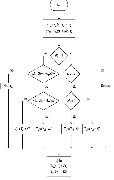
Fig.9. Flowchart of INC MPPT
The Incremental Conductance (INC) method uses the slope of the PV panel Power-Voltage characteristics to track the maximum power point. This method is deals with the fact that the slope of the PV panel power curve is zero at the MPP, positive for values of output power smaller than MPP, and negative for values of the output power greater than MPP [9]. It is called as Incremental Conductance because in the algorithm, the instantaneous conductance is continuously measured and a comparison is done with the incremental conductance, i.e, change in conductance value, and when both the conductance becomes equal then that point will be the maximum power point (MPP) [7].The P-V characteristics used in the INC method is shown below:
Fig.10. P-V curve of PV system
The governing equations of INC MPPT are as follows:
M P P
d V I d P
d V d V
0
M P P d I I V
d V
M P P
d I I
d V V
The main advantage of INC method is that it provides an effective solution under quickly changing atmospheric conditions. Furthermore it has less oscillation around MPP in comparison with P&O.
5 R
ESULTSThe Boost converter is set to work at the switching frequency of 5 kHz, an inductor of 50 mH and the capacitor of 2 mF.
Table 1. Parameters of 200W PV Panel
(G=1000 W/m2& T=250C)
Parameters Variables Values
Maximum Power
Pmax 200W
Voltage at Pmax Vmax 26.3V
Current at Pmax Imax 7.61A
S.C.Current Isc 8.21A
O.C.Voltage Voc 32.9V
Temp coefficient of Voc
Kv -0.123 V/K
Temp coefficient of Isc
Ki 0.0032 A/K
tabular form and their combined waveforms are also shown. All the above systems are simulated under constant conditions i.e. constant environmental conditions (constant values of Irradiance and Temperature). The systems are simulated for the duration of 1 sec.
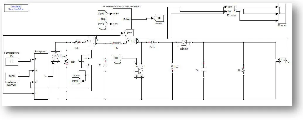
Fig.11. PV system with INC MPPT technique with Boost Converter developed in MATLAB/simulink
2402 Fig.13.Combined output at G=1000 W/m2 and T=250C Fig.14.Combined output at G=1000 W/m2 and T=300C
Fig.15. Combined output at G=800 W/m2 and T=250C
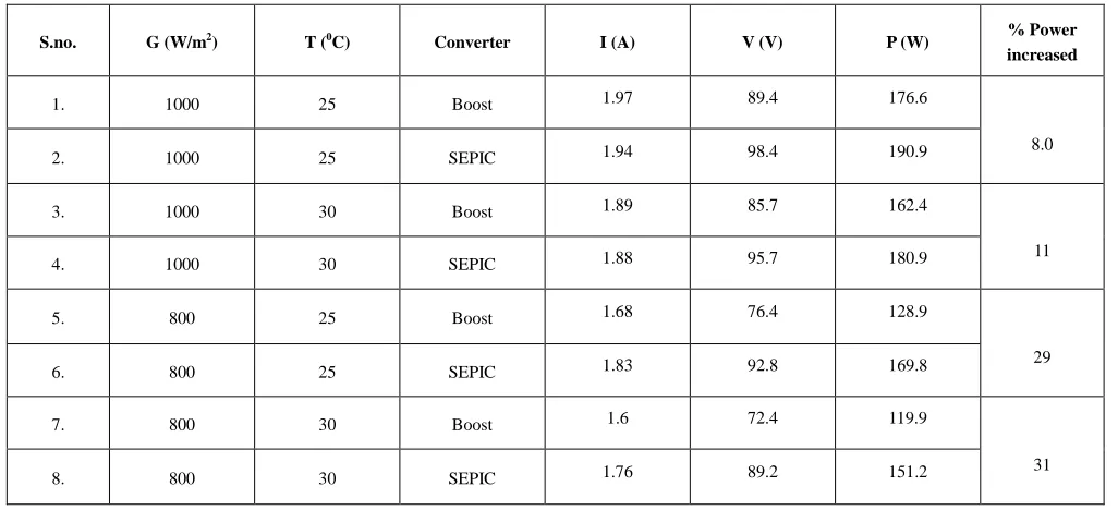
Table 2.Comparison Table under Constant Environmental Conditions
S.no. G (W/m2) T (0C) Converter I (A) V (V) P (W) % Power
increased
1. 1000 25 Boost 1.97 89.4 176.6
8.0
2. 1000 25 SEPIC 1.94 98.4 190.9
3. 1000 30 Boost 1.89 85.7 162.4
11
4. 1000 30 SEPIC 1.88 95.7 180.9
5. 800 25 Boost 1.68 76.4 128.9
29
6. 800 25 SEPIC 1.83 92.8 169.8
7. 800 30 Boost 1.6 72.4 119.9
31
8. 800 30 SEPIC 1.76 89.2 151.2
6
CONCLUSIONS
This paper presents a study of PV module implemented with INC MPPT technique with two converters, i.e. Boost converter and SEPIC converter. The system is tested under different environmental conditions and is simulated on MATLAB. The waveforms for different conditions and simulink model of the system are also shown along with the final results in tabular form. From the results, we can conclude that the output power from both the converters starts decreasing whether temperature increases or irradiation decreases. When the temperature is increased from T= 250C to T= 300C, the output power in Boost Converter decreases from P= 176.6 W to P= 162.4 W, but with SEPIC Converter, the output power decreases from P= 190.9W to P= 180.9W. It shows that the decrease in output power is more with the Boost Converter than in SEPIC Converter. Similar patterns can be observed in the case with decreasing Irradiation level from G= 1000W/m2 to G= 800W/m2. Also, if we look at the waveforms of both the converters, we will notice that the voltage profile in SEPIC converter is more stable in comparison to the Boost Converter. It is evident that SEPIC converter is a two stage process and it gives a regulated voltage than a single stage Boost converter. So we can conclude that a PV module with INC MPPT can be best implemented with SEPIC converter to get an efficient and stable system. No doubt, the SEPIC converter system will be costly but will be more efficient and system specific.
7
R
EFERENCES[1] M. G. Villalva, J. R. Gazoli and E. R. Filho, “Modeling and
circuit-based simulation of photovoltaic arrays,” 2009
Brazilian Power Electronics Conference, Bonito-Mato Grosso do Sul, 2009, pp. 1244-1254.
[2] M. S. Ngan and C. W. Tan, “A study of maximum power
point tracking algorithms for stand-alone Photovoltaic
Systems,” 2011 IEEE Applied Power Electronics
Colloquium (IAPEC), Johor Bahru, 2011, pp. 22-27.
[3] W. Xiao, W. G. Dunford, P. R. Palmer and A. Capel,
"Regulation of Photovoltaic Voltage," in IEEE Transactions on Industrial Electronics, vol. 54, no. 3, pp. 1365-1374, June 2007.
[4] G. R. Walker and P. C. Sernia, "Cascaded DC-DC converter
connection of photovoltaic modules," in IEEE Transactions on Power Electronics, vol. 19, no. 4, pp. 1130-1139, July 2004.
[5] R. B. Darla, "Development of maximum power point tracker
for PV panels using SEPIC converter," INTELEC 07-29th International Telecommunications Energy Conference, Rome, 2007, pp. 650-655.
[6] Saravanan, N. Ramesh Babu, Vivek Siwach and Gaurav
Kumar, “Design and Analysis of MPPT Based PV System Using Boost and SEPIC Converter”, International Journal of Applied Engineering Research, Vol. 10 No.30 pp. 23016-23021, 2015.
[7] M. A. Elgendy, B. Zahawi and D. J. Atkinson, "Assessment
of the Incremental Conductance Maximum Power Point Tracking Algorithm," in IEEE Transactions on Sustainable Energy, vol. 4, no. 1, pp. 108-117, Jan. 2013.
[8] A. Malhotra and P. Gaur, "Comparative study of dc-dc
converters in solar energy systems," 2014 International Conference on Advances in Computing, Communications and Informatics (ICACCI), New Delhi, 2014, pp. 816-820.
[9] A. Safari and S. Mekhilef, "Incremental conductance MPPT