Pathak et al. World Journal of Engineering Research and Technology
AUTOMATIC STREET LIGHT CONTROL SYSTEM USING LDR AND
MICROCONTROLLER
Rohit Pathak*, Prakash Singh Munda, Vinay Kumar, Sanjeev Manjay, Sushil Singh
Electronics and Communication Engineering, RKDF Institute of Science and Technology,
Bhopal (M.P), India.
Article Received on 26/06/2015 Article Revised on 15/07/2015 Article Accepted on 10/08/2015
ABSTRACT
This paper aims at designing and executing the advanced
development in embedded systems for energy saving of street lights.
Nowadays, human has become too busy, and is unable to find time
even to switch the lights wherever not necessary. The present system is
like, the street lights will be switched on in the evening before the sun
sets and they are switched off the next day morning after there is
sufficient light on the roads. This paper gives the best solution for
electrical power wastage. Also the manual operation of the lighting
system is completely eliminated. In this paper the two sensors are
used which are Light Dependent Resistor LDR sensor to indicate a day/night time and the
photoelectric sensors to detect the movement on the street. The microcontroller PIC16F877A
is used as brain to control the street light system, where the programming language
used for developing the software to the microcontroller is C-language. Finally, the system
has been successfully designed and implemented as prototype system.
KEYWORDS: Introduction-block diagram, Sections-required hardware/ software, circuit diagram and proposed model, advantages, applications, future aspects, Conclusions.
INTRODUCTION
The idea of designing a new system for the street light that do not consume huge amount of
electricity and illuminate large areas with the highest intensity of light is concerning each
World Journal of Engineering Research and Technology
WJERT
www.wjert.org
*Correspondence for Author Rohit Pathak Electronics and Communication Engineering, RKDF Institute of Science and Technology, Bhopal (M.P), India.engineer working in this field. Providing street lighting is one of the most important
and expensive responsibilities of a city. Lighting can account for 10-38% of the total
energy bill in typical cities worldwide[1]. Street lighting is a particularly critical concern
for public authorities in developing countries because of its strategic importance for
economic and social stability. Inefficient lighting wastes significant financial resources
every year, and poor lighting creates unsafe conditions. Energy efficient technologies and
design mechanism can reduce cost of the street lighting drastically.
Manual control is prone to errors and leads to energy wastages and manually dimming
during mid night is impracticable. Also, dynamically tracking the light level is
manually impracticable. The current trend is the introduction of automation and remote
management solutions to control street lighting[2].
There are various numbers of control strategy and methods in controlling the street
light system such as design and implementation of CPLD based solar power saving
system for street lights and automatic traffic controller[1], design and fabrication of
automatic street light control system[3], automatic street light intensity control and road
safety module using embedded system[4], automatic street light control system[5], Intelligent
Street Lighting System Using Gsm[6], energy consumption saving solutions based on
intelligent street lighting control system[7] and A Novel Design of an Automatic Lighting
Control System for a Wireless Sensor Network with Increased Sensor Lifetime and
Reduced Sensor Numbers[8].
In this paper two kinds of sensors will be used which are light sensor and photoelectric
sensor. The light sensor will detect darkness to activate the ON/OFF switch, so the
streetlights will be ready to turn on and the photoelectric sensor will detect movement
to activate the streetlights. LDR, which varies according to the amount of light falling on
its surface, this gives an inductions for whether it is a day-night time, the photoelectric
sensors are placed on the side of the road, which can be controlled by microcontroller
PIC16f877A. The photoelectric will be activated only on the night time. If any object
crosses the photoelectric beam, a particular light will be automatically ON. By using
this as a basic principle, the intelligent system can be designed for the perfect usage of
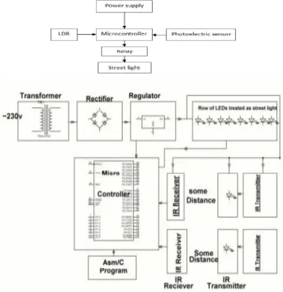
The block diagram of street light system as shown in Fig. 1 consists of
microcontroller, LDR, and photoelectric sensor. By using the LDR we can operate the
lights, i.e. when the light is available then it will be in the OFF state and when it is dark
the light will be in ON state, it means LDR is inversely proportional to light. When
the light falls on the LDR it sends the commands to the microcontroller that it
should be in the OFF state then it switch OFF the light, the photoelectric sensor will be
used to turn ON or OFF the light according to the presence or absent of the object. All
these commands are sent to the controller then according to that the device operates. We
use a relay to act as an ON/OFF switch.
Street lights are the major requirement in today’s life of transportation for safety
purposes and avoiding accidents during night. Despite that in today’s busy life no one
bothers to switch it off/on when not required. The project introduced here gives
solution to this by eliminating manpower and reducing power consumption.
This requires three basic components i.e. LDR, Sensors and microcontroller. During
daytime there is no requirement of street lights so the LDR keeps the street light off until
the light level is low or the frequency of light is low the resistance of the LDR is high. This
prevents current from flowing to the base of the transistors. Thus the street lights do not glow.
As soon as the light level goes high or if light falling on the device is of high enough
frequency, photons absorbed by the semiconductor give bound electrons enough energy
to jump into the conduction band. The resulting free electron (and its hole partner) conduct
electricity, thereby lowering resistance. Now the circuitry goes in on condition and the block
diagram represented here starts working.
BLOCKDIAGRAM
When LDR allows the current to flow this block diagram of circuitry goes into
working condition. IR sensors start emitting IR rays via IR transmitters. As soon as any
vehicle crosses or obstructs the path of IR rays and prohibits it to reach at IR receivers
the microcontroller starts getting the blockage signals. The programming installed in
microcontroller starts running which basically presented here allow three street lights to
glow that are- the light in front of vehicle, behind the vehicle and parallel to vehicle
making backward and Forward Street visible. Transformer converts the high 230V AC to
12V AC, Rectifier converts it into DC. For voltage regulation we are using LM 7805 and
replaces HID lamps by engaging a programmable microcontroller that controls the street
light on/off conditions.
Figure 1: Block Diagram.
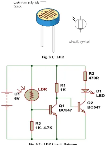
2. MATERIAL AND METHODS 2.1LDR
An LDR (Light dependent resistor), as its name suggests, offers resistance in response to the
ambient light. The resistance decreases as the intensity of incident light increases, and vice
versa. In the absence of light, LDR exhibits a resistance of the order of mega-ohms which
decreases to few hundred ohms in the presence of light. It can act as a sensor, since a varying
voltage drop can be obtained in accordance with the varying light. It is made up of cadmium
this circuit as a darkness detector. The LDR is a resistor as shown in Fig. 2, and its
resistance varies according to the amount of light falling on its surface. When the LDR
detect light its resistance will get decreased, thus if it detects darkness its resistance will
increase.
Fig. 2(1): LDR
Fig. 2(2): LDR Circuit Daigram
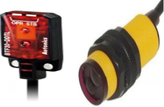
2.2 PhotoelectricSensor
Photoelectric sensors use a beam of light to detect the presence or absence of an object. This
technology is used to identify size and contrast of an object. 4 kinds of general purpose
combined with optic & electric technology and are widely applied in various fields of
industry for its optimized functions, quality, application flexibility and reliability while
remaining strongly competitive with its price among the whole industry. Application areas of
photoelectric sensors include industrial automation lines, elevators, parking facilities,
logistics services, semiconductor devices, packaging machines and construction areas. The
photoelectric sensor specifications are illustrated in Table 1.
Fig. 3 Photoelectric sensor
Table 1: Photoelectric sensor specifications PhotoelectricSensors(MC005)
Sensing range 3-80 cm
Sensing object Translucency, opaque Supply voltage, current DC 5V, 100mA
Output operation Normally open
Output DC three-wire system (NPN) Diameter, Length 18mm, 45mm
Ambient temperature -25_70
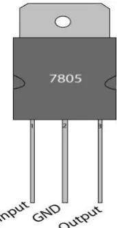
2.3 RegulatedPowerSupply
Usually, we start with an unregulated power supply ranging from 9volt to 12volt DC. To
make a 5volt power supply, KA7805 voltage regulator IC as shown in Fig. 4 has been
Fig. 4: Power supply regulator (IC 7805)
7805 is a voltage regulator integrated circuit. It is a member of 78xx series of fixed linear
voltage regulator ICs. The voltage source in a circuit may have fluctuations and would not
give the fixed voltage output. The voltage regulator IC maintains the output voltage at a
constant value. The xx in 78xx indicates the fixed output voltage it is designed to provide.
7805 provides +5V regulated power supply. Capacitors of suitable values can be connected at
input and output pins depending upon the respective voltage levels. The KA7805 is simple
to use. Simply connect the positive lead form unregulated DC power supply (anything from
9VDC to 24VDC) to the input pin, connect the negative lead to the common pin and
then turn on the power, a 5 volt supply from the output pin will be gotten.
Pin Description of IC 7805
Pin No Function Name
1 Input voltage (5V-18V) Input 2 Ground (0V) Ground 3 Regulated output; 5V (4.8V-5.2V) Output
2.4Relays
A relay is an electrically operated switch. Many relays use an electromagnet to mechanically
operate a switch, but other operating principles are also used, such as solid-state relays.
Relays are used where it is necessary to control a circuit by a low-power signal (with
complete electrical isolation between control and controlled circuits), or where several
circuits must be controlled by one signal. The first relays were used in long distance telegraph
circuits as amplifiers: they repeated the signal coming in from one circuit and re-transmitted
it on another circuit. Relays were used extensively in telephone exchanges and early
A type of relay that can handle the high power required to directly control an electric motor
or other loads is called a contractor. Solid-state relays control power circuits with no moving
parts, instead using a semiconductor device to perform switching. Relays with calibrated
operating characteristics and sometimes multiple operating coils are used to protect electrical
circuits from overload or faults; in modern electric power systems these functions are
performed by digital instruments still called "protective relays".
Relays are remote control electrical switches that are controlled by another switch, such
as a horn switch or a computer as in a power train control module. Relays allow a small
current flow circuit to control a higher current circuit. Several designs of relays are in use
today, 3-pin, 4-pin, 5-pin, and 6-pin, single switch or dual switches. Relays which come
in various sizes, ratings, and applications, are used as remote control switches. Fig. 5
shows different types of relays. In this paper, the 4-pin relay will be used.
Fig. 5: Different types of relays
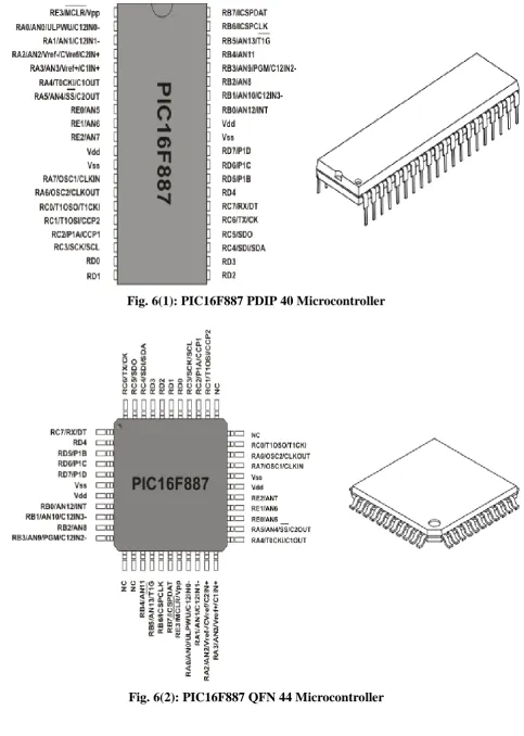
PIC16F887 Microcontroller
The PIC16F887 is one of the latest products from Microchip. It features all the components
which modern microcontrollers normally have. For its low price, wide range of application,
high quality and easy availability, it is an ideal solution in applications such as: the control of
different processes in industry, machine control devices, measurement of different values etc.
Some of its main features are listed below.
RISC architecture
o Only 35 instructions to learn
o All single-cycle instructions except branches
o Factory calibrated
o Software selectable frequency range of 8MHz to 31KHz
Power supply voltage 2.0-5.5V
o Consumption: 220uA (2.0V, 4MHz), 11uA (2.0 V, 32 KHz) 50nA (stand-by mode)
Power-Saving Sleep Mode
Brown-out Reset (BOR) with software control option 35 input/output pins
o High current source/sink for direct LED drive
o software and individually programmable pull-up resistor
o Interrupt-on-Change pin
8K ROM memory in FLASH technology
o Chip can be reprogrammed up to 100.000 times
In-Circuit Serial Programming Option
o Chip can be programmed even embedded in the target device
256 bytes EEPROM memory
o Data can be written more than 1.000.000 times
368 bytes RAM memory A/D converter:
o 14-channels
o 10-bit resolution
3 independent timers/counters Watch-dog timer
Analogue comparator module with
o Two analogue comparators
o Fixed voltage reference (0.6V)
o Programmable on-chip voltage reference
PWM output steering control Enhanced USART module
o Supports RS-485, RS-232 and LIN2.0
o Auto-Baud Detect
Master Synchronous Serial Port (MSSP)
Fig. 6(1): PIC16F887 PDIP 40 Microcontroller
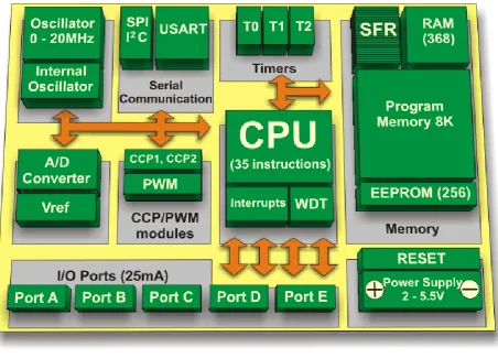
Fig. 6(3): PIC16F887 Block Diagram
3. RESULTSANDDISCUSSIONS
The project aims were to reduce the side effects of the current street lighting system, and
find a solution to save power. In this project the first thing to do, is to prepare the inputs
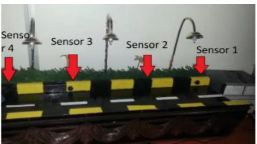
and outputs of the system to control the lights of the street. The prototype as shown in
Fig. 8 has been implemented and works as expected and will prove to be very useful and
will fulfill all the present constraints if implemented on a large scale. Figure 7 shows the
street light system, from the figure it can be seen that, all lighting column are OFF,
because there is no any object passes through the street, even though the weather is night.
This is the idea of using the microcontroller to control each lighting column alone. When
any object passes in front specific photoelectric sensor the lighting column which
Fig. 7: CircuitDiagram
PROGRAM
int light;
void read_ldr()
{
unsigned int adc_value=0;
adc_value=ADC_Read(0);
light = 100 – adc_value/10.24;
if(light>=80) // SWITCH of the light when light is 80 percent
{ PORTB.F1=0; } else { PORTB.F1=1; } } void main() { TRISB=0X00; PORTB=0X00; Adc_Init(); while (1) { read_ldr(); } } ADVANTAGES
1. Complete elimination of manpower 2. Reduced energy costs.
3. Reduced green house gas emissions. 4. Reduced maintenance costs.
5. Higher community satisfaction.
Applications
1. Balcony, stair case, parking Lightings. 2. Street lights.
3. Garden Lights.
FutureAspects
1. Pole damage detection with the addition of a suitable sensor.
2. Taxi call buttons on lamp posts to signal to the network management centre to generate a
Taxi call to the appropriate location.
3. If the system has traffic speed sensors then this information could be used to manage
traffic speed via the dimming of the streetlights. If the average traffic speed is too fast
during evening and night hours, this could be used to trigger a slight dimming of the
streetlights. The level of dimming would be imperceptible to motorists but they
would slow down, regardless, in response to the slightly diminished lighting. A five
percent light reduction slows traffic but is not noticeable to motorists.
4. With the added intelligence in the lamp, you can add further features to increase
HID lamp life, such as softer start-up and protection against re-igniting an already hot HID
lamp, since this shortens the lamp life.
5. Information management.
CONCLUSIONS
This project of “ AUTOMATIC STREET LIGHTS” is a cost effective, practical,
ecofriendly and the safest way to save energy. It clearly tackles the two problems that world
is facing today, saving of energy and also disposal of incandescent lamps, very efficiently.
According to statistical data we can save more that 40 % of electrical energy that is now
consumed by the highways. Initial cost and maintenance can be the draw backs of this
project. With the advances in technology and good resource planning the cost of the
project can be cut down and also with the use of good equipment the maintenance can
also be reduced in terms of periodic checks. The LEDs have long life, emit cool light, donor
have any toxic material and can be used for fast switching. For these reasons our project
presents far more advantages which can over shadow the present limitations. Keeping in
view the long term benefits and the initial cost would never be a problem as the investment
The project has scope in various other applications like for providing lighting in industries,
campuses and parking lots of huge shopping malls. This can also be used for surveillance
in corporate campuses and industries.
ACKNOWLEDGEMENTS
I would like to express my special thanks of gratitude to my Guide (Er. Vivek Yadav) who
gave me the golden opportunity to do this wonderful project on the topic (Automatic Street
Light Control System), which also helped me in doing a lot of Research and I came to know
about so many new things I am really thankful to them. Secondly I would also like to thank
my parents and friends who helped me a lot in finalizing this project within the limited time
frame.
REFERENCES
1. D. A. Devi and A. Kumar. Design and Implementation of CPLD based Solar
Power Saving System for Street Lights and Automatic Traffic Controller, International
Journal ofScientific and Research Publications, Vol. 2, Issue11, November 2012.
2. J. Mohelnikova. Electric Energy Savings and Light Guides, Energy &
Environment, 3rd IASME/WSEAS International Conference on, Cambridge, UK,
February, 2008; pp. 470-474.
3. M. A. Wazed, N. Nafis, M. T. Islam and A. S. M. Sayem. Design and Fabrication of
Automatic Street Light Control System, Engineering e-Transaction, June 2010; 5(1):
27-34.
4. R. Priyasree, R. Kauser, E. Vinitha and N. Gangatharan, Automatic Street Light
Intensity Control and Road Safety Module Using Embedded System, International
Conference on Computing and Control Engineering, April 2012.
5. K. S. Sudhakar, A. A. Anil, K. C. Ashok and S. S. Bhaskar, Automatic Street Light
Control System, International Journal of Emerging Technology and Advanced
Engineering, May 2013; 3: 188-189.
6. K.Y. Rajput, G. Khatav, M. Pujari, P. Yadav. Intelligent Street Lighting System Using
Gsm, International Journal of Engineering Science Invention, March 2013; 2(3):
60-69.
7. M. Popa, C Cepisca, Energy Conjumption Saving Solutions Based on Intelligent
Street Lighting Control System. U.P.B. Sci. Bull., April 2011; 73: 297-308.
Design of an Automatic Lighting Control System for a Wireless Sensor Network
with Increased Sensor Lifetime and Reduced Sensor Numbers, Sensors, Vol. 11: PP.
8933-8952.
9. www.atmel.com, www.beyondlogic.org, www.wikipedia.org, www.howstuffworks.com,