Akpama et al. World Journal of Engineering Research and Technology
PERFORMANCE EVALUATION OF FUZZY LOGIC CONTROL OF
INDUCTION MOTOR
Dr. Akpama E. J.*, Oboho K. and E. E. Ekpenyong
Dept of Elect/Elect, Cross River University of Technology, Calabar, Cross River State.
Article Received on 03/06/2017 Article Revised on 24/06/2017 Article Accepted on 14/07/2017
ABSTRACT
Speed control of induction motors has been a challenge mostly during
industrial processes. These motors are used to carry out different task
at different speeds. A three phase induction motor is a constant speed
motor; therefore, it is difficult to control its speed especially
maintaining a constant speed with load variation. There is a tradeoff in
efficiency and power factor when the speed of the motor is being controlled. Different
methods of speed control have been proposed and used with their attended advantages and
disadvantages. In this paper, Fuzzy logic is used to control the speed of an induction motor
under load variation. The control architecture includes some defined fuzzy rules, which
portray a nonchalant relationship between the two inputs; speed error (e) and change in error
(Δe), and the output frequency or change in control ( ). The errors are evaluated according
to the rules by the defined member functions. The system model is simulated in
MATLAB/SIMULINK and the simulated results presented. The results obtained using a
conventional PI controller and the designed Fuzzy Logic Controller has been studied and
compared. The FLC presents better performance in terms of stability, precision and reliability
when compared to the PI.
KEYWORDS: Fuzzy logic, Speed control, Proportional integral controller, induction motor.
INTRODUCTION
The induction motor is indispensable in the industry, the workhorse in industrial processes
and controls. In years past, dc motors were predominantly used in this regard due the
World Journal of Engineering Research and Technology
WJERT
www.wjert.org
SJIF Impact Factor: 4.326*Corresponding Author Dr. Akpama E. J.
Dept of Elect/Elect, Cross River University of
challenge of speed control in induction motors. The emergence of AC drives (power
electronics) has made induction motors more popular because today speed control in
induction motors is possible and easy, notwithstanding other benefits of induction motors
compared to dc motors. Generally, variable-speed drives for induction motors require wide
operating range of speeds and fast torque response, regardless of load variation, and acts as
industrial energy savers. Voltage source inverter-fed induction motors are most preferred for
variable speed drive applications. Recorded advantages of Induction motor includes; Simple
and rugged design, No brushes, Low maintenance cost, high efficiency and ability to operate
in hazardous environment. Induction motors have the following demerits; (a) Load is
dependent on slip, (b) Position sensor may be required, and (c) it is a fixed-speed motor. Due
the above, developing a control system for induction machine operation becomes imperative.
It is a known fact that, speed control is one of the imposed constraints in induction motors. In
the last decades, studies in this direction have created more research interest and various
methods of controls have been developed.[1,2] Induction motor speed can be controlled from
either the stator or rotor circuits. If the control is from the stator circuit, then variables of
interest could be; Volt/Hertz or frequency, stator poles, supply voltage.[3] From the rotor
circuit, adding external resistance, Cascade control method, or injection of slip frequency emf
are options of speed control. The closed loop volt/hertz control method is developed here to
control the speed of a 7.5kW, three phase induction motor. To maintain a constant speed on
load, Fuzzy Logic Controller (FLC) is introduced and the result is improved performance
compared to that of a Proportional Integral (PI) controller. According to,[4,5] both Fuzzy
Logic Controller (FLC) and Proportional Integral (PI) Controller are artificial intelligent
method which has found high application in most of the non-linear systems like the electric
motor drives. Fuzzy Logic Controllers (FLCs) are advantageous because they are
economical, operate over ranges of operating conditions and they easily adapt to natural
language.[6,7,8] It deals with reasoning that is approximate rather than fixed and exact.
Compared to the traditional binary set, fuzzy logic variables may have a true value that
ranges in degrees between 0 and 1[9,10] The FLC provides a means of converting a linguistic
control strategy based on expert knowledge into an automatic control strategy.[11]
Stator Voltage and Frequency Control
The Stator V/f control is carried out by varying the voltage to frequency ratio of the supply to
This will prevent the saturation of the air-gap flux due to increase in flux. By keeping the
ratio of voltage/frequency constant, the motor delivers its rated torque at its rated speed.[6,7] In
all the various speed control mechanisms, the volts/hertz control scheme is very popular
because it provides a wide range of speed control with good running and transient
performance also known as scalar control mode, where the input and output are speed, unlike
the vector control mode where it is torque/flux as input and reference current as output.
Voltage/frequency converters help to vary the speed over a wide range.
The conventional control methods have some demerits as listed below;[2]
It depends on the accuracy of the mathematical model of the system,
The expected performance is almost impossible due to motor saturation and thermal
variation,
Accurate performance is exhibited only at one operating speed when classical linear
control is employed.
Choosing the right coefficient with varying parameters like the set point is difficult
because coefficient must be chosen properly for the expected result,
To implement a conventional control methodology, it is necessary to have knowledge of
the system’s model that is to be controlled.
Due to the above, the design for high performance control becomes complex and very costly.
Therefore, the proposal of an advanced control system based on artificial intelligence
technique also called intelligent control and self-organizing system is imperative. The
emergence of high power, high speed and low cost modern processors along with power
technique switches like IGBT has made intelligent control a good potential in electric drives.
Artificial intelligent techniques is categorized into; hard and soft computation.[1,12] Soft
computation is used widely in electric drives system.
Therefore, to overcome the complexities of conventional controllers, FLC is designed and
implemented in many motor control applications, owing to its knowledge based algorithm,
better non-linearity handling features and impedance of the processed plant modeling. FLC
owes its popularity to its linguistic control; it tries to replicate the human thought process in
its control algorithm hence an exact mathematical model for the system to be controlled is not
required. This allows intermediate values to be defined, conventional evaluations like
method has been proven to make good performance in terms of stability, precision and
reliability. It takes two inputs which are; error (e) and change in error (Δe) to model a FLC
with the help of IF-THEN rules with an added advantage of no complicated hardware.
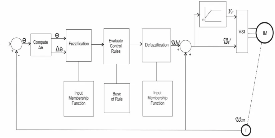
Speed Control of Three Phase Induction Motor
Figure 1, shows the block diagram of an induction motor speed controller. The frequency and
supply voltage to the induction motor are varied such that it operates at steady state, and
desired speed. The choice of speed as the reference signal is justified since the parameter of
interest is speed. A feedback mechanism is used to provide the quality of automation to the
control system. The instantaneous output signal is fed back to the system’s input to achieve
the desired output. Change-of-error is the derivative of speed error, and both errors (e) and
change-of-error (Δe) are fed into the Fuzzifier. The inference system then processes these two
fuzzy inputs using the fuzzy control rules and the database, which are defined based on the
chosen membership function and fuzzy rule table, to give an output fuzzy variable. The
Defuzzified output gives a scripts value which is the change-of-control of the system ( ).
This is then added to the motor speed which in turn forms the input to the Voltage
Source Inverter and V/f controller.
Fig. 1: Speed Control system of Induction Motor using Fuzzy Logic Controller.
The VSI receives voltage signal from the V/f controller and frequency signal to generate a
three phase voltage whose frequency and amplitude can be varied by the Fuzzy Logic
Controller. These Three phase voltages are then fed to the induction motor thus generating
Membership Function Design
The membership functions are designed for Error (e), Change in Error (∆e) and output ( )
as shown in figure 2. The linguistic label used in both the Error (e) and the change in Error
(∆e) includes; Negative Large (NL,) Negative Medium (NM), Negative Small (NS), Zero
(ZZ), Positive Small (PS), Positive Medium (PM) and Positive Large (PL). The linguistic
label used for the output ( ) are, Negative Large (NL), Negative Medium (NM), Negative
Small (NS), Negative Very Small (NVS), Zero (ZZ), Positive Very Small (PVS), Positive
Small (PS), Positive Medium (PM) and Positive Large (PL).
Figure 2: FIS Fuzzy Editor with 2 Inputs and 1 Output.
Membership Function of FIS showing Error, Change in Error and Output.
Rule Base Design for Output
The Rule base for the decision making of the output of the inference system consists of 49
rules using the IF-THEN rule base. This output which is the change in error is added to the
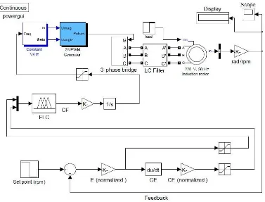
motor speed to give supply frequency which goes into the v/f block. The developed
SIMULINK model is shown in figure 4 below:
Table 1: Fuzzy Rule Table for Output ( ).
∆e NL NM NS ZZ PS PM PL
NL NL NL NL NM NS NVS ZZ
NM NL NL NM NS NVS ZZ PVS
NS NL NM NS NVS ZZ PVS PS
ZZ NM NS NVS ZZ PVS PS PM
PS NS NVS ZZ PVS PS PM PL
PM NVS ZZ PVS PS PM PL PL
Figure 3: SIMULINK Model of the Fuzzy Logic Controller.
As shown above, set point is the desired speed of the motor, while the feedback signal is the
measured value of the induction motor speed. The measured speed is multiplied by (30/π) to
convert the (rad/s) unit into (rpm) unit. The error signal (which is the actual speed subtracted
from the desired speed) and its derivative are used as input for FLC block. The output of FLC
is the required change in frequency which will be integrated continuously, while the
saturation block is used to limit the output frequency within the system limitations. The
control signal, which represents the frequency in this case, is sent to V/Hz block which will
maintain a constant ratio between voltage and frequency to keep the torque constant while the
speed varies. The output of this block is sent to SVPWM generator which will accordingly
produce a PWM signal that meets the input frequency. Resulted PWM signal is used to
trigger the MOSFET Hex-bridge to produce a similar signal with amplified voltage in the
inverter output.
Simulation and presentation of Results
Several simulations were carried out on the PI and FLC controllers under different operating
conditions of the induction machine. The performance of PI and FLC models with a little
Figure 4: Speed Response at 900 rpm. Figure 5: Control Signal at 900 rpm.
The speed response of the proposed control system when the reference speed = 900rpm,
while the second shows the output of FLC (the control signal). In this simulation, a load was
applied at time = 1.5s, then it was removed at time = 3s. The applied load caused the motor
speed to go down below the reference speed. At the same time, the control signal went up to
compensate the loss of speed. When the applied load was removed, the control signal went
down to maintain the actual speed equal to the set point. Figures 6, 7, show the speed
response of FLC system while applying two loads with time interval between them.
Figure 6: Speed Response at 1000 rpm. Figure 7: Control Signal at 1000 rpm.
As seen in the speed response at 1000rpm, load 1 was applied at time = 2 s, while load 2 was
applied at time = 5 s. Since load 2 is greater than load 1, its effect on the motor speed is
greater. Consequently, the control signal is proportional to load disturbance, the actual motor
speed is maintained equal to the reference speed after a short time of change because of load
disturbance. For comparison, the following simulation tests show the speed response of the
Figure 8: Speed Response for Sudden Figure 9: Speed Response for Sudden change Change of Load in Load and the Reference Speed.
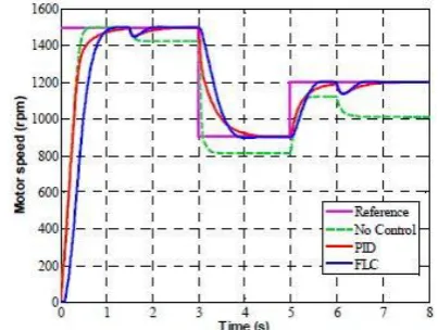
DISCUSSION OF RESULTS
The simulation result is presented showing the performance of the machine with different
controllers; without control, with PI and with FLC, with apply load at time = 2 s and another
load at time = 5 s. The Multi-reference speeds; 1500, 900 and 1200 rpm were used with load
disturbance at time = 3 s and at time = 5 s. As noticed in both figures, there is a sharp
response to different loads as indicated, both PI and FLC showed a good response to this
change. Table 2 shows the performance indices of FLC and PI, for of rise time and settling
time, when multi-step speed input is applied.
Table 2: Comparison of FLC and PI.
Reference Speed (rpm) Rise Time (s) Settling Time (s)
FLC PI FLC PI
1500 0.5392 0.4026 0.9496 0.9685
900 0.5387 0.6476 0.8074 1.1844
1200 0.3850 0.5201 0.5736 0.8461
It is clear from the results that, FLC showed better performance compared to PI controller.
FLC also showed the ability to control speed of the three-phase induction motor and provide
an accurate and fast response with relatively no overshoot and no steady state error.
CONCLUSION
The speed of industrial motors are controlled for best performance, control of electric
machine is one challenge operators have, mostly for induction motors with constant speed.
Industrial loads most cases are variable and the motor speed should also be variable. Here
better performance and faster response when compared with PI. A sample test was done
using the following input speeds: 700, 900, 1200 and 1400 rpm, and the resulting THD was
2.3%, 2.9%, 1.8% and 3% respectively, which is less than 5%, the acceptable harmonic
distortion as recommended by IEEE standards.
REFERENCES
1. Ned Mohan, Tore M. Undeland and William R. Robins, Power Electronic, New York,
John Wiley and Sons, Press 1991.
2. L.A. Zadeh, “Fuzzy sets, Information and Control”, Vol 8, pp. 338 – 353, 1965.
3. L.A. Zadeh, “Outline of a New approach to the Analysis of Complex System and Decision
Processes”, 1973.
4. L.A. Zadeh, “Making Computers think like people”, IEEE Spectrum, 1984; 8: 26 – 32.
5. PavolFedor and Daniela Perduková, “A simple Fuzzy Controller Structure,”
ActaElectrotechnicaetInformatica, 5(4): 1-4, 2005.
6. J. Martinez Garcia, J.A. Dominguez, “Comparison between Fuzzy Logic and PI Controls
in Speed Scalar Control of induction machine,” CIRCE – ge3 – Departamento de
IngenieriaElecricaC.P.S., Universidad de Zaragoza, Conf. Paper.
7. G. El-saady, A.M. Sharaf, A. Makky, M.K. Sherriny, and G. Mohammed, “A High
Performance Induction Motor System Using Fuzzy Logic Controller,” IEEE Trans, 1994;
0-7803-1772-6/94, 1058-1061.
8. O. Yagishita, O. Itoh, and M. Sugeno, “Application of fuzzy reasoning to the water
purification process,” Ed. Amsterdam: North Holland, 1995; 19-40.
9. O. Itoh, K. Gotoh, T. Nakayama and S. Takamizawa, “Application of fuzzy control to
activate sludge process,” in proc. 2nd
IFSA Congress, Tokyo, Japan, July 1987; 282-285.
10.S. Yasunobu, S. Miyamoto and H. Ihara,”Fuzzy control for automatic train operation
system,” in proc. 4th
IFAC/ IFIP/ IFORS int. Congress on Control in Transportation
Systems, Baden-Baden, April 1983.
11.S. Yasunobu and S. Miyamoto,”Automatic train operation by predictive fuzzy control”, in
Industrial Application of fuzzy control, M. Sugeno, Ed. Amsterdam: North-Holland,
1985; 1-18.
12.S. Yasunobu, S. Sekino and T. Hasegawa,”Automatic train operation and automatic crane
operation systems based on predictive fuzzy control”, in proc. 2nd IFSA Congress. Tokyo,
13.S. Yasunobu and T. Hasegawa, “Evaluation of an automatic container crane operation
system based on predictive fuzzy control,” Control Theory Advance Technology, 1986;
2(3): 419-432.
14.IEEE Std 519-1992, IEEE Recommended Practices and Requirement for Harmonic
Control in Electrical.