Integration and Management of Multiple Radios in
Satellite-Terrestrial based Aeronautical Communication
Networks
J.Baddoo
1, P. Gillick
1, P. Pillai
3,*, R. Morrey
1, M. Naylor
1, A. Waller
1, A. Smith
2, K. Xu
3, M. Ali
3and
Y. Cheng
31Thales UK Research and Technology, Worton Drive, Worton Grange, Reading, RG2 0SB, UK 2Thales UK, Manor Royal, Crawley, RH10 9HA, UK
3Schools of Engineering Design and Technology, University of Bradford, Bradford, UK
Abstract
The Single European Sky Air Traffic Management (ATM) research programme SESAR has identified continued growth in demand for aircraft communications as air traffic increases and communications become more network centric. Alongside existing systems such as VHF Data Link Mode 2, new systems such as LDACS and AeroMACS are being proposed along with satellite communications. This growth is likely to increase the size, weight and cost of avionics radio communication equipment, so there is a need to examine new radio architectures which will help limit these increases. The EU project SANDRA aims to design and demonstrate an integrated communications system using software defined radio techniques. In this paper, the concepts behind the integrated communications system are described, including improved modularity using high-speed digital links, security, redundancy and certification. The specific requirements of the integrated radio and the details of the proof-of-concept demonstrator are also outlined. This paper also presents a Collaborative Radio Resource Management (CRRM) scheme to support seamless aeronautical communications using satellite and terrestrial access technologies. The CRRM adopts and extends the IEEE 802.21 Media Independent Handover (MIH) framework and the ETSI Broadband Satellite Multimedia (BSM) SI-SAP concept to split the CRRM functions between the upper layers (layer 3 and above) and the lower layers (link layer and physical layer) of an aircraft terminal. A Joint Radio Resource Manager (JRRM) provides the abstraction layer for mapping higher layer functions into lower layer functions to enable collaboration. The CRRM scheme and its associated general signalling procedures are described in detail. Through the CRRM scheme, the connection establishment functions and seamless handovers between different radio technologies are performed by combining MIH primitives and BSM primitives.
Keywords: integrated modular radio, integrated communications system, aeronautical communications system, software defined radio, avionics, BSM, media independent handovers, joint radio resource management. Received on 27 September 2011; accepted on 5 January 2012; published on 29 March 2012
Copyright © 2011 Baddoo et al., licensed to ICST. This is an open access article distributed under the terms of the Creative Commons Attribution licence (http://creativecommons.org/licenses/by/3.0/), which permits unlimited use, distribution and reproduction in any medium so long as the original work is properly cited.
doi: 10.4108/trans.ubienv.2012.e4
1. Introduction
*Over the years, systems for aeronautical
communications have grown and evolved in order to meet increasing demands and support new technologies.
* Corresponding author, Email:[email protected]
(Air Traffic Management) Research Joint Undertaking (SESAR JU) programme, whose founding members are the European Commission and EUROCONTROL [2].
Typical application areas for aeronautical communications include Air Traffic Management (ATM), Aircraft Operational Control (AOC), Airline Administrative Communication (AAC) and Airline Passenger Communications (APC). In order to support growth in these areas, additional radio systems have been proposed, including:
EUROCONTROL L-band Digital Aeronautical Communication System (LDACS) to augment the VHF systems
European Space Agency Iris Programme for Air Traffic Management (ATM)
High-bandwidth satellite communications systems based on Digital Video Broadcasting (DVB) standards.
Aeronautical Mobile Airport Communications System (AeroMACS) [3], based on Worldwide Interoperability for Microwave Access (WiMAX)
Different technologies will provide various advantages and provide flexibility to the system with very high reliability. It is also envisaged that such a system would be able to simultaneously operate the different radio communication technologies. Hence different data i.e. ATS, AOC, AAC and APC data can be sent over different radio technologies depending on the QoS and security requirements of the data. However, supporting these new systems represents a considerable extra burden of size, weight, complexity and cost in aircraft avionics equipment, should the new radio systems be implemented in stand-alone equipment as has been traditionally the case. Moreover, although it has been suggested that the new systems will eventually replace the legacy communications systems, the likelihood is that there will be a lengthy period where aircraft will need to be fitted with all of the systems for global interoperability. This is the forecast expressed by SESAR, and the additional airborne equipment required during this transition phase severely threatens the realisation of the future communications vision.
A different approach aiming at a broader level of integration is therefore needed in order to achieve the required increase of capacity, safety, security and efficiency of air transportation operations while at the same time keeping the complexity and cost of on-board networks and equipment at a sustainable level.
In October 2009, the European Commission (EC) launched a Seventh Framework Programme called SANDRA [4] to examine “Seamless Aeronautical Networking through integration of Data links, Radios, and Antennas”. SANDRA aims to design, specify and develop an integrated aircraft radio communication architecture to improve efficiency and cost-effectiveness by ensuring a high degree of flexibility, scalability, modularity and reconfigurability. The programme will examine a number of integration possibilities, including:
the integration of communication service provision at the network layer using the Internet Protocol (IP) as a unification technology
the integration of radios which typically cover the realisation of the physical layers, data link layers and network layers of specific radio communications waveforms
the integration of an L-Band antenna with a Ku-Band antenna.
SANDRA aims to provide a truly integrated modular approach for a global aeronautical network and communication architecture. The overall programme is designed to lead to performance evaluation of the system in a laboratory environment, followed by flight trials. A number of concepts relating to the integration and management of radio systems are described in the following sections, covering issues such as system boundaries, separation of processing from transceivers, security, segregation, redundancy, certification and the provision efficient Radio Resource Management (RRM). The goal of RRM is to optimize bandwidth utilisation and QoS across the different radios, in the presence of traffic flows generated by services with different requirements. The SANDRA functional architecture is briefly described, splitting it into the Integrated Router (IR) and the Integrated Modular Radio (IMR). The SANDRA Integrated Communication System concept that constitutes the IMR is then presented. Radio resource allocation is performed through the Collaborative Radio Resource Management (CRRM) framework to partition the functional entities between the IR and IMR for the configuration and reconfiguration of radio links during the connection management. The functional architecture of the CRRM is derived and presented, based on two existing standards: the ETSI Broadband Satellite Multimedia (BSM) [5] SI-SAP (Satellite Independent – Service Access Point) concept and the IEEE 802.21 MIH framework [6]. Special attention is then paid to the SANDRA Proof-of-Concept IMR demonstrator, looking at some of the design choices that are being made and highlighting how the programme will exercise IMR concepts. Finally, the SANDRA IMR demonstrator is presented.
2. SANDRA Overview and Functional
Architecture
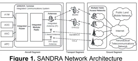
The SANDRA programme aims to design and demonstrate an integrated communications system for civil aviation. The network architecture is illustrated in Figure 1 and supports the following waveforms:
Analogue VHF and Voice Data Link Mode 2 (VDL2) in the VHF band [7]
Inmarsat Broadband Global Access Network (BGAN) in L-Band [8]
Digital Video Broadcasting - Satellite - Second Generation (DVB-S2) in Ku-band (receive only) [9].
Figure 1. SANDRA Network Architecture
The SANDRA Terminal in Figure 1 is an integrated communications system made up of an Integrated Router (IR), an Integrated Modular Radio (IMR) and a number of antennas. The IR carries out high level functions such as routing, security, Quality of Service (QoS) provision and mobility. The IMR carries out low level functions such as the radio communication layers, radio resource allocation and QoS mapping. The physical separation between the IR and the IMR has the advantage of increased modularity and the ability to identify distinct management roles and functions for higher layer and lower layer components with IP providing the convergence. The Antennas include a hybrid Ku/L band Integrated Antenna (IA), a VHF antenna and a C-band antenna. The IA is a hybrid Ku/L band SatCom antenna to enable an asymmetric broadband link. The Ku-band system is used for receive mode only to reduce the number of antennas and the L-band will use the INMARSAT BGAN link capable of both transmit and receive functions. The VHF antenna will be used to provide transmit and receive links for VDL2 mode ATC and AOC voice communications services. The C-band antenna will be used for AeroMACS to enable aircraft-airport and inter-domain aircraft-airport connectivity. The various end-systems i.e. ATS, AOC, AAC and APC are all connected to the IR.
In the transport segment, VDL Mode 2, BGAN, DVB-S2 and AeroMACS provides connectivity between the aircraft segment and the ground segment supported, by the IMR and their corresponding Radio Access Networks (RANs) on the ground. The selection of the appropriate transport network is made within the SANDRA connection manager (CM) that spans across the IR and the IMR based upon applications, policies, regulatory constraints, service availability, quality of service and other factors.
The ground segment consists of multiple operators; multiple Radio Access Networks (RANs) and their corresponding core networks, the ATN, the Internet and possibly the Public Land Mobile Network (PLMN, for passenger communications). The RANs can also be connected directly to the ATN and the PLMN on the ground. In order to provide mobility service and security services for aeronautical communications, functional components such as the mobility server, security and authentication server are required in the ground segment to provide corresponding mobility information services as well as security services. These components will be
provided by the ATS/AOC/AAC and APC service providers of the ATN on the ground.
The realisation of the IMR within the programme will now be described, illustrating how it will demonstrate some of the key concepts in the integrated communications system approach.
3. Integrated Communication System
Concepts
3.1 System Boundaries
The system boundary for an integrated communications system includes all avionics radio sub-systems and is illustrated in Figure 2. The boundary for the maximum system covers the following interfaces:
Maintenance interface – this allows the system to be installed and maintained, and includes the ability to upgrade software and firmware
Configuration interface – this allows the system to be configured, for example, setting certain internal IP addresses
Avionics interface – this provides access to avionic systems outside the IMR, for example, to obtain or provide navigation information
Cockpit interface – this provides voice and data services to the cockpit
Cabin interface – this provides voice and data services to the cabin, for example, through the In Flight Entertainment (IFE) system
Electromagnetic wave interfaces for radio services - the Radio Frequency (RF) electromagnetic wave interfaces at the antennas. The actual antennas are within the system boundary
Power input - this provides power to the system.
Power
Cabin Interface Cockpit Interface Maintenance Interface Configuration Interface Avionics Interface
. . . .
System Boundary
External Electromagnetic
Waves
Internal Electromagnetic
Waves
Antennas
Electronic Equipment
Figure 2. System Boundary for Integrated Communications System
3.2 Candidate Waveform Examples
different waveforms that may need to be supported, but is not a comprehensive list.
Table 1. Candidate Waveform Examples
The tables include the currently anticipated Design Assurance Level for each system, but this may change in the future.
3.3 Separation of Processing from
Transceivers
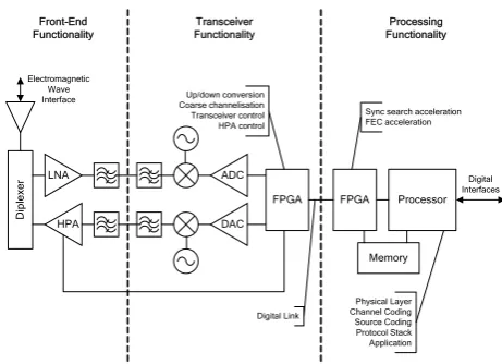
Key to the integrated communications system approach is the partitioning of the radio functionality in order to identify common functionality which can be combined or hosted more efficiently. With this in mind, radio functionality may be split into the following major areas:
Front-end Functionality – This covers antennas and other items that may need to be located close to the antennas, such as antenna matching units, diplexers, low noise amplifiers and high power amplifiers.
Transceiver Functionality – This broadly covers the analogue aspects of radio technology, typically operating in the Intermediate Frequency (IF) and Radio Frequency (RF) domains. It usually includes amplifiers, mixers and filters to provide up and down conversions between an IF representation of and an RF representation of signals. It also covers the conversion between analogue and digital representation of signals.
Processing Functionality – This broadly covers the digital aspects of radio technology, where processing is typically carried out in Field Programmable Gate Arrays (FPGAs) and processors. The later have traditionally been split into Digital Signal Processors (DSPs) and General Purpose Processors (GPPs), but this distinction is less important today since some processors can carry out both digital signal processing and general purpose processing efficiently.
D
ip
le
xe
r
FPGA Processor
LNA
HPA
ADC
DAC
FPGA
Memory Up/down conversion
Coarse channelisation Transceiver control HPA control
Sync search acceleration FEC acceleration
Physical Layer Channel Coding Source Coding Protocol Stack Application
Digital Interfaces Electromagnetic
Wave Interface
Digital Link Front-End
Functionality
Transceiver Functionality
Processing Functionality
Figure 3. Example Partitioning of Radio Functionality
An example partitioning of radio functionality is illustrated in Figure 3. There is some flexibility in the location of certain functions. For example digital up/down conversion and coarse channelisation may be viewed as part of transceiver functionality or processing functionality. Alternatively, it may be split between the two.
Avionics radio equipment has traditionally been based on a federated architecture where a dedicated radio is provided for each type of radio system (e.g. VHF). The above functional partitioning illustrates an opportunity for an integrated communications system where the processing capability is common across different radio systems and can either be reused or shared. This approach is similar to the Integrated Modular Avionics (IMA) [10] approach which moved the provision of other types of avionics equipment from a federated architecture to an integrated architecture. In fact, the integration of the communications system within the IMA is also being examined within the SANDRA programme.
3.4 Digital Serial Links
The partitioning of radio functionality described above supports an architecture where a common baseband processing solution is used in combination with transceiver functionality that is designed for different systems or area of the spectrum. This gives the potential for cost saving by maximising reuse of the design, isolating the transceiver functionality if required and physically separating the location of transceiver functionality and processing functionality. It also provides architectural flexibility since in some systems, it is desirable for the transceiver functionality to be located close to the antenna to reduce cable losses.
Peripheral Computer Interconnect Express (PCIExpress), Ethernet and the Common Public Radio Interface (CPRI) [11].
Point-to-point links are attractive since they are faster, simpler and more reliable than multi-drop links. Modern high-speed serial links include equalisers at the receivers to improve signal integrity. The higher speeds are also achieved because the clock is embedded in the signal, and there is no need to keep several electrical lines synchronised as is required with parallel buses.
3.5 Security
Security is an important consideration in the provision of avionics equipment and can be viewed as covering confidentiality, integrity and availability of systems and data.
Confidentiality problems can be caused, for example, by eavesdropping on communications and gaining unauthorised access to systems through loopholes in the access control measures.
In terms of integrity, attackers may, for example, attempt to modify data, inject false data or simply selectively delete data and thereby cause the aircraft systems to make incorrect decisions due to erroneous or missing information. This could be achieved by intercepting communications, for example, or by introducing malicious software onto a processing platform.
Availability problems can be caused by attackers blocking communications or causing vital systems to fail through, for example, exploitation of software bugs in the applications or their underlying operating systems.
There are several groups and organisations that are looking at various aspects of security for avionics. The activities of these groups and organisations are summarised below.
Airlines Electronic Engineering Committee (AEEC) is an airlines and airframe manufacturers standards group that co-ordinates several security activities for avionics. The standards and working groups of interest are:
ARINC 811 – Aircraft Information Security Process. This is a model for assessing security risk, implementing appropriate countermeasures, operating these countermeasures and feeding results back to risk assessment.
ARINC Manager of Air-Ground Interface Connection (MAGIC) – This group is looking at integrated communications systems on board aircraft, initially for airline and passenger systems but with the ability to extend this to ATM and AOC systems later on.
Radio Technical Commission for Aeronautics (RTCA) Inc is a US based organisation that develops aviation standards. A similar organisation in Europe is the European Organisation for Civil Aviation Equipment (EUROCAE). The RTCA SC-216 group is working on security issues, and so is the EUROCAE WG-72 group.
Both groups are collaborating to develop the following security related documents:
Minimum Aviation System Performance Standards (MASPS) for Aeronautical Electronic and Networked Systems Security
Security Assurance and Assessment Processes and Methods for Safety-related Aircraft Systems.
Air Transport Association of America, Inc (ATA) is an airline trade association based in the US. The following working group and specification cover security matters:
Digital Security Working Group – this group provides a forum for addressing the application of digital security technologies and establishing best practice and conventions.
Spec 42: Aviation Industry Standards for Digital Information Security – this specifies identity management solutions based on Public Key Infrastructure (PKI) technology.
EUROCONTROL is the European organisation for the safety of air navigation, and the Federal Aviation Administration (FAA) is an agency of the US government that regulates and oversees all aspects of civil aviation in the US. The following study has been carried out by EUROCONTROL and the FAA:
Communications Operating Concept and Requirements for the Future Radio System (COCR) [12] – This focuses on air traffic control and air operations, and includes a security risk assessment in these areas. Confidentiality is rated as of low importance except for business needs, but integrity and availability are rated as potentially of very high importance across a wide range of systems. The main recommendation is the use of cryptographic communications security as the main form of protection.
The above specifications and studies for security are likely to be relevant to the integrated communications system approach.
3.6 Segregation
Segregation applies at two levels in the context of the integrated communications system approach. First of all there is often a need to segregate the provision of services, for example, segregating cockpit services used by the crew from the cabin services used by passengers. Secondly, where software applications share the same resources (e.g. processor and memory) there is a need to segregate the software applications so that they cannot interfere with each other.
segregation between the various applications was clear and generally defined in hardware such that a fault occurring in that unit could easily be prevented from affecting other applications. However, the obvious drawback with the federated approach is the use of more resources than necessary, which often requires duplication for fault tolerance, further exacerbating the problem. IMA has emerged as a design approach challenging the federated architecture by reducing the costs associated with acquisition, space, power, weight, cooling, installation and maintenance. IMA uses a single computer system (with replication for fault tolerance), to provide a common computing resource for several applications. This is achieved by employing an operating system that provides space (i.e. memory) and time partitioning, for example, an ARINC 653 compliant operating system. Similar issues apply in the integrated communications system approach. Cockpit and cabin services segregation can be achieved through software partitioning, or by using different processing platforms for the different services. Software partitioning can also be provided through an appropriate operating system. However, it should be noted that the tolerable latencies in software defined radio applications are generally less than those in current IMA applications. Latency issues limit the number of waveform applications that can share the same processing platforms using time partitioning.
3.7 Redundancy
Authorities, such as the FAA, specify a minimum level of redundancy of equipment that must be operational before an aircraft is allowed to take off. This redundancy is specified so that a single failure does not cause the loss of any vital communication channel.
In the federated approach, redundancy is provided by replicating dedicated equipment, taking up space and adding weight. In the integrated communications system approach, there are more opportunities for supporting redundancy, including the ability to switch from one processing unit to another in the case of failure.
3.8 Certification
Certification is one of the most difficult areas in the development of avionics systems. It needs, for good reasons, to be done thoroughly, and tends to err on the side of caution to ensure that safety requirements are fully satisfied. The subject is large and complex and addressed in various documents, including the following:
SAE ARP4754 Guidelines for Development of Civil Aircraft and Systems [13]
RTCA DO-178B / ED-12B: Software Considerations in Airborne Systems and Equipment Certification [14]
RTCA DO-248B: Final Report for Clarification of DO-178B [15]
RTCA DO-254 / ED-80: Design Assurance Guidance for Airborne Electronic Hardware [16]
RTCA DO-297: Integrated Modular Avionics (IMA) Development Guidance and Certification Considerations [17].
A careful examination is required between the certification impact for dedicated radio equipment as in the federated approach, and the certification impact where common processor platforms are employed, as in the integrated communications system approach.
4. The SANDRA RRM Architecture
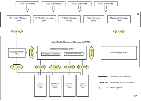
The SANDRA project concentrates on radio link selection among the four heterogeneous radio access technologies during admission control, packet scheduling and handover processes. In SANDRA, a collaborative radio resource management (CRRM) architecture framework where radio link selection decisions are made collaboratively between the IR and the IMR has been derived. To provide efficient RRM among heterogeneous networks, QoS and routing related parameters have to be considered along with the real-time link conditions and characteristics by the CRRM framework. The latter monitors and manage the resources available in the different radio links to ensure that the application QoS/SLA requirements are met during connection establishment and handover processes. Figure 4 shows the CRRM functional and protocol architecture of the SANDRA terminal. From the protocol stack point of view, the application layer supports APC, AAC, AOC and ATS services. The design of the CRRM is based on two existing standards: the ETSI Broadband Satellite Multimedia (BSM) [5] SI-SAP (Satellite Independent – Service Access Point) concept and the IEEE 802.21 MIH framework [6].
4.1 SANDRA CRRM Functional Entities
In Figure 4, the IR represents the network layer of the OSI stack and contains the following functional entities:
IP Route Manager (IRM): This entity provides IP routing and IP address management functions. It interacts with the IP Mobility Manager (IMM) to enable mobility management functions to be carried out. For NEMO [18] support, the IRM will manage the IPv6 and IPv4 prefixes assigned to the mobile network. It is also responsible for setting up Mobile IP tunnels to the correspondent node and reverse tunnels to the Home Agent using IPv6 encapsulation.
IP QoS Manager (IQM): This entity maps application layer QoS parameters onto to those in the IP layer. It also performs packet classification, packet buffering and packet scheduling functions.
IP Mobility Manager (IMM): This entity enables the SANDRA terminal to roam from one network domain to another while maintaining session connection during handover when there is a change in the point of attachment of the terminal. Specifically, the IMM is responsible for neighbour discovery, router advertisement, mobility header management and binding update processing. It is also responsible for handling multihoming and network mobility (NEMO) functionalities.
Policy Manager (PM): The PM manages and maintains a database of the flow-specific policies or rules that specify the traffic flow characteristics (e.g. QoS requirement, cost, security level, etc.) that the radio links may need to meet. These policies may also contain preferences of radio links for individual flows. These rules will facilitate the link selection decision for traffic flow with policy constraints.
Resource Manager (RM): This entity monitors the availability of the different radio links, any reserved resources on them and maintains a view on the different IP traffic flows. It identifies whether there is a need for more resources based on the type of session requests or on the current status of the IP queues.
The IMR representing the data-link and the physical layer of the OSI stack consists of the four different radio technologies as presented in Section 2. Within the IMR, a SANDRA specific Joint Radio Resource Manager (JRRM) is located above the four radio stacks. It is responsible for managing and controlling the resources made available to the underlying radios in a uniform and consistent manner and provides a single common interface between the IR and the IMR. Functional entities included in the JRRM are the Adaptation Manager (AM), the Link Manager (LM) and the Packet Switcher (PS). Both the AM and the LM are control plane entities whereas the PS is a user plane entity.
The AM supports protocol mapping for protocol conversion between the IR and the IMR and address resolution functions for mapping between network layer
identities onto link specific identities. In addition, it also carries out a switching function equivalent to the MIH Function (MIHF) for handover to support handover services including the Event Service (ES), Information Service (IS), and Command Service (CS), through service access points (SAPs) defined by the IEEE 802.21 MIH [6, 19-20] working group.
The LM performs link selection and link configuration functions and together with the RM in the IR forms the Connection Manager (CM). The CM as a whole acts as a MIH user in the MIH framework.
The PS is responsible for switching data packets received from the IR in the user plane to the destined radio modules according to a packet switching table generated and passed by the address resolver in the AM during connection establishment. The packet switching table essentially contains the mapping of the QIDs [5] defined in the BSM SI-SAP concept onto different radio link identifiers (Link IDs). As a result, each data packet can be switched directly to the radio modules without passing through the AM in the user plane.
4.2 SANDRA CRRM Mechanism
The CRRM mechanism defined in SANDRA considers collaborative connection management, collaborative QoS management and collaborative mobility management in relation to admission control, packet scheduling and handover functions as described in the previous section through cross-layer collaboration between functional entities in the IR and the IMR and using the session concept. While the IR is responsible for managing the network layer connections, the IMR is responsible for the link layer connections.
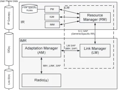
The collaborating entities, the RM and the LM, are grouped into a single cross-layer entity - the CM. The relationships of the CM with the PM, IQM, IMM and AM is depicted in Figure 5.
Figure 5. Collaborative connection management
4.2.1 The SANDRA Sessions concept
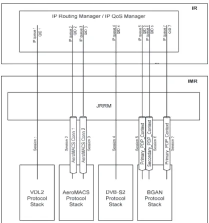
the IR and the IMR in order to provide efficient RRM and to meet the QoS requirements. Sessions are used to map corresponding data queues within the IP layer and the link layer.
In SANDRA, the term “session” corresponding to a single connection is between a given IP queue and a link-layer queue. As shown in Figure 6, there is a one-to-one mapping between the IP queues and the sessions. In BSM [5, 21, 22], the QID is used for mapping IP queues to BSM queues. This QID concept has been adopted and extended within SANDRA to identify the IP queues in the IR and the corresponding session with the IMR. Hence, the sessions will be represented by a QID, which is unique for every session.
Every session between the IR and the IMR will have a certain QoS profile based on the desired application requirements that are being carried by the session. It is important that the QoS parameters of the IP queue are mapped to the session QoS and then further mapped to the QoS of the link-layer queue.
Different sessions are required for the different radio links within the SANDRA system. Hence, if two active radio links are present, then at least two sessions are required to carry data over the two radio links, i.e. one for each radio link. In other words, the same session cannot be used for carrying data over two radio links.
Figure 6. The SANDRA Sessions concept
Radio technologies like VDL2 and DVB-S2 only provide single type of radio bearers and hence limited RRM functionalities. Only a single type of radio connection may be established between the terminal and the ground infrastructure of these radio technologies at any given time. Therefore within SANDRA, only a single session is required between the IR and the IMR for these radio technologies. Newer radio technologies like BGAN and AeroMACS support multiple radio bearers of different QoS simultaneously. As such, multiple sessions may be
present between the IR and the BGAN and AeroMACS radio stacks.
A session can be general or dedicated, depending on whether the radio request(RR) is a general RR or a specific RR. A general session means that a session is established without specific restrictions apart from satisfying the QoS requirements. In this case, the LM can make decisions on link selection - to select the most suitable link available which can satisfy the requirements specified in the RR. In addition, user traffic from multiple applications can be transmitted on the same session. The RM in the IR will make the decisions on how to use these general sessions to transmit user data. Thus, the IR and IMR make collaborative decisions on the session establishment. While the IR decides how user data from multiple applications will be transmitted on different sessions, the IMR decides on the most suitable link access technology for the requested session. A dedicated session is established for a specific application; only data from this specific application can be transmitted on the requested session. If a RR from the IR includes policy based routing decision, for example a dedicated radio link should be used for this specific RR due to regulatory or geographical constraints, the LM in the JRRM of the IMR should try to set up the session on the specified radio link. In this case, the IR makes the decision on which link access technology should be used and informs the IMR through a specific RR so that the IMR can collaborate by allocating resource on the specified radio link for the requested session.
4.2.2 Collaborative Connection Management
Connection management functions include connection establishment, connection termination and connection modifications. These are carried out by the RM in the IR and the LM in the IMR collaboratively to manage the network layer and link layer connections.
As shown in Figure 5, the PM is connected to a database of the application flow-specific rules and policies. These policies may govern the decision on which radio links can be used for different applications. Such policies may be based on the type of applications, type of aircraft, the location of the aircraft and flight path, etc. It may also be based on security and regulatory requirements that may restrict the applications to be transported over a specific radio link. Applications that do not have strict requirements specified by the policy manager may be transported over any one of the available links that satisfies the application QoS.
would be responsible for managing the resources required for such traffic also. As such, the RM carries out the first level of decision making. It is responsible for deciding when new resources are required, when resources are released, etc. It will also perform link selection decision upon receiving dedicated session requests.
The LM is responsible for controlling the radio links and performs the second level of RRM related decision making for connection establishment. In the case of general session request, the LM performs suitable link selection by mapping the application QoS requirements onto the resource availability and the quality of the available links. The radio link that can most satisfy the QoS requirements will be selected and a session between the IR and the selected radio link will be established.
4.2.3 Collaborative QoS Management
In relation to satisfying the QoS requirements upon a service request, the IQM in the IR will control and manage the IP Queues. On receiving data from the higher layers, the IP QoS manager performs packet classification based on the type of application and perform packet marking using Diffserv code points. Codes corresponding to the QoS requirements are added to the IP header of each packet before sending it to the IMR. The IR also performs packet level scheduling of all incoming application packets based on their QoS requirements. The IR sees the different sessions between the IR and the IMR as different data tunnels though which different data needs to be sent. Application data as a result of a dedicated session request will be sent over a dedicated session, otherwise they can be sent over any available sessions that may satisfy its QoS requirements.
The IMR needs to be able to also setup appropriate link-layer connections that meet the desired QoS that is requested by the IR. This requires mapping the higher layer QoS parameters to the link-specific QoS parameters. If the radio link network cannot meet the desired QoS then another suitable link may be selected that could satisfy the QoS. If none of the available radio links is able to meet the desired QoS then the session request is rejected. The IR may then re-issue the resource request with the modified QoS parameters.
The IP QoS Manager in the IR is responsible for monitoring the IP queues to make sure that there are no packet drops within the system. The Packet Switcher in the IMR is also responsible to monitor any packet drops. These performance metrics need to be reported to the management unit in the IR via the management plane. When the existing sessions are not able to satisfy the QoS needs of the application, then a new session may be set up or additional resources may be requested on the existing radio links. This would require QoS re-negotiation with the ground networks.
4.2.4 Collaborative Mobility Management
The SANDRA system supports multihoming where the IR can be connected to multiple ground networks via different radio links at any given time. Due to location
constraints, handover support across different radios is required. For example, the AeroMACS radio technology would be primarily available only at the airports during taxiing, taking-off and landing whereas satellites will be the primary means for communications when the aircraft are at cruising attitude. In addition, an aircraft may move out of coverage of a given satellite link and then enter into another. The fast movement of the aircraft presents another complexity for mobility management in terms of handover.
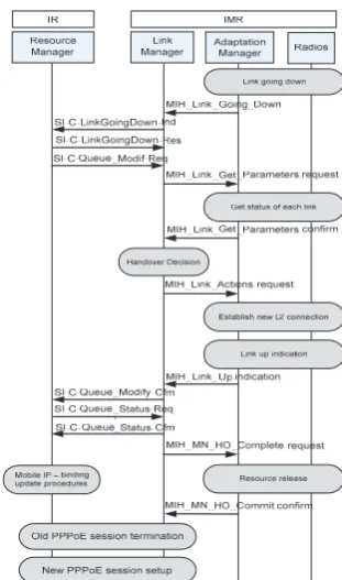
In SANDRA, NEMO will be used by the IR for providing local and global mobility solutions and seamless mobility across the different networks. The IR and the IMR work in a collaborative manner to provide a cross layer mobility management solution. The IR may request the IMR to handover sessions from one radio link to another if there are some rules that dictate that different links may be used by an application during different phases of the flight. The IMR will also periodically monitor the link conditions and if it detects that a given link is no longer available then it will initiate the handover procedure. In the case of a general session, the Link Manager will select another suitable active link that may already be active for other general sessions. The Link Manager will then handover the old link to the new link and informs the IR about the handovers. The IR may then initiate the NEMO/Mobile IP binding updates to the ground networks. In case a special session is already active on this link, the LM will inform the IR about this session so that the Resource Manager may perform suitable link selection for this session.
4.3 CRRM Signalling Procedures
Figure 7. General session establishment
From Figure 7, the resource request in a new session establishment procedure is handled by the ETSI BSM SI-C-Queue_Open-Req primitive that demands specific QoS requirements to be fulfilled by the IMR link setting. Upon reception of this primitive, the IMR makes use of MIH primitives to check the link status of each available radio technology then perform the link selection function to establish L2 connection on the selected radio technology. Then, the ESTI BSM SI-C-Queue_Open-Cfm primitive is used by the IMR to confirm the establishment of L2 connection with the IR. Finally the SI-C-Queue_Status primitives are exchanged to get the IP setting information and a new PPPoE session is established for the SANDRA session identified by a newly assigned QID by the IMR. Figure 8 presents the L2 connection establishment procedure for handover using the ETSI BSM SI-C-Queue_Modify-Req primitive that indicates a new queue modify request due to a link will become unavailable that triggers a handover event on the existing QID session(s). Consequently, QoS re-negotiation is required on the new link. This phase is then accomplished by making use of both ETSI BSM and MIH primitives as can be seen from the signalling message exchanges between the IR and the IMR. Following the SI-SAP primitives, the IR will perform the mobile IP update, then terminate the old PPPoE session and establish the new PPPoE session for the same SANDRA session.
Figure 8. General Mobile controlled handover
5. SANDRA Proof-of-Concept Integrated
Modular Radio Demonstrator
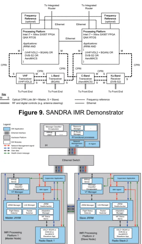
The SANDRA IMR demonstrator is illustrated in Figure 9, showing two common processing platforms, optional frequency references, three transceivers and one receiver. The processing platforms are connected to the transceivers and receiver by CPRI. The processing platforms also connect to each other and to the external Integrated Router (IR) via Ethernet.
Processing Platform Intel i7 + Xilinx SX95T FPGA QNX RTOS Applications: JRRM AND {
(VHF/VDL2 + BGAN) OR DVB-S2 OR AeroMACS } VHF Transceiver (VHF/VDL2) L-Band Transceiver (BGAN) C-Band Transceiver (AeroMACS) Ku-Band Receiver (DVB-S2) Frequency Reference (optional) Frequency Reference (optional) Processing Platform Intel i7 + Xilinx SX95T FPGA QNX RTOS Applications: JRRM AND {
(VHF/VDL2 + BGAN) OR DVB-S2 OR AeroMACS } To Integrated
Router To Integrated Router
Key
Optical CPRI Link (M = Master, S = Slave) RF and digital controls (e.g. antenna steering)
M M M M
M
M M
S S
S S S
S S
M M
S Frequency reference
Ethernet
To Front End To Front End To Front End To Front End Ethernet Ethernet Ethernet CPRI CPRI CPRI CPRI CPRI CPRI
Figure 9. SANDRA IMR Demonstrator
Link Manager
Adaptation Manager Packet Switcher
VDL2+ BGAN or DVB-S2 or AeroMACS Waveform App. Resource Manager PPPoE client Message Classifier/ Encapsulator IP Route Manager JRRM Healthchecker Flight Status Detector JRRM Manager PPPoE Server Message Classifier/ Encapsulator ... ... Link Manager Adaptation Manager Packet Switcher
VDL2+ BGAN or DVB-S2 or AeroMACS Waveform App. JRRM Healthchecker Flight Status Detector JRRM Manager Ethernet Interface SW Application Hardware Platform SW Modules Network Management signal Control signal User data Health check message
PPPoE Server Message Classifier/ Encapsulator WF Status Servo WF Status Servo
Figure 10. JRRM SW Architecture
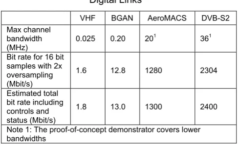
Figure 10 depicts the software architecture of the SANDRA terminal down to the Radio Stacks. One IR, one Master Node and one Slave Node hardware platforms are represented by the grey boxes. On each IMR processing platform, there are five applications running:
The Supervisor Application: This is responsible for launching the JRRM and the various waveforms. The JRRM can then tell the Supervisor Application which application to launch. If a waveform application goes down, the supervisor will inform the JRRM.
The VT Manager: The Virtual Tunnel (VT) Manager in the IMR works as PPPoE server as well as packet encapsulator converting between IP packets and SANDRA specific SAP messages. It is responsible for establishing PPPoE connections with the IR based on the real time information updated by the JRRM, such as service names and IP addresses. It is also controlled by the JRRM whether it works as Master mode or Slave mode.
The JRRM application: The core JRRM adaptation layer responsible for the collaboration RRM. It
consists of the JRRM Manager, Packet Switcher, Healthchecker, Link Manager, Adaptation Manager, and Flight Status Detector.
The Waveform application: There are three combinations of the waveforms being loaded into one of the two FGPA boards, the VDL2+BGAN, the DVB-S2 or the AeroMACS.
The IMR agent: This is a network management application which is responsible for collecting network management related information. It consists of three main parts: a management interface, a Management Information Base (MIB), and the core agent logic.
The JRRM can control and manage the various radio links and control which radio link is loaded onto the processing platform. It can then establish connection over the links according to the various QoS requirements. Handover of connections from one link to another can also be performed if a radio link is lost. The JRRMs on the two platforms work in a Master-Slave configuration, whereby a hot swap can take place if the current master JRRM fails due to any hardware or software failure. These provide the reliability and redundancy feature that is critical for the aeronautical communication systems.
5.1 High-Speed Digital Serial Link
Selection
The IMR architecture employs a high-speed digital serial link between transceiver functionality and the processing functionality illustrated in Figure 3. This link mainly carries baseband samples of the receive signal and baseband samples or symbols of the transmit signal. In addition, it carries control and status signals. An important requirement for this link is the required bit rate. The estimated bit rate for each system is given in Table 2, based on 16 bit samples and two times oversampling with reference to the minimum Nyquist requirement for the bandwidth of interest.
Table 2. Bit Rate Requirement for High-Speed Digital Links
VHF BGAN AeroMACS DVB-S2
Max channel bandwidth
(MHz) 0.025 0.20 20
1 361
Bit rate for 16 bit samples with 2x oversampling (Mbit/s)
1.6 12.8 1280 2304
Estimated total bit rate including controls and status (Mbit/s)
1.8 13.0 1300 2400
Note 1: The proof-of-concept demonstrator covers lower bandwidths
In radio communications applications, other controls such as fast Automatic Gain Control (AGC) or inner loop power control can require significantly shorter response times. For example, the maximum round trip delay in the CPRI specification (excluding cable delays) is 5 μs, in order to support the UTRA-FDD (UMTS Terrestrial Radio Access - Frequency Division Duplexing) inner loop power control.
The required latency of the link depends on the types of applications that need to be supported and the desired location of functionality at each end of the link. A round trip delay of the order of 100 μs means that fast responses such as fast AGC or inner loop power control will need to be implemented at the transceiver unit. A round trip delay with the CPRI figure of 5 μs means that fast responses such as fast AGC or inner loop power control can be implemented at the processing unit.
The required alignment of a transmit burst to a receive signal varies from system to system. One method of achieving alignment is to drive the Analogue to Digital Converter (ADC) and Digital to Analogue Converter (DAC) from the same clock source, thus providing a fixed relationship between transmit samples and receive samples. A transmit function in software or firmware can then set up a transmission aligned to the timing defined by the ADC and DAC pair. In this scenario, the only impact of the performance of the link (i.e. its latency) will be on the amount of memory required in the transceiver unit to buffer receive and transmit samples.
Additional requirements include environmental requirements and support for locating transceiver functionality and processing functionality at different ends of the aircraft, for example through the use of optical fibres.
The following candidate high-speed serial interfaces have been examined:
PCI Express (PCIe)
Serial RapidIO (SRIO)
Common Public Radio Interface (CPRI).
CPRI has been selected for use in the SANDRA demonstrator since it has the following desirable characteristics:
specifically designed for links between transceiver functionality and processing functionality
supports line rates of up to 6144 Mbit/s, well in excess of the requirements of Table 2
supports electrical and optical media, with the latter supporting distances of over 10 km
supports the distribution of frequency references, should this be desirable
flexible enough to support a variety of radio waveforms
round trip delay is guaranteed to be as low as 5 μs since unlike PCIe and SRIO, it is frame based rather than packet based
supports a number of topologies such as chains, trees and rings.
5.2 Processing Card and FPGA Card
Selection
The processing platform for the SANDRA demonstrator is hosted in a 19” 4U industrial PC with an Intel i7 processor. A COTS XMC card with a Xilinx SX95T FPGA and Small Form-factor Pluggable (SFP) connectors provides an FPGA capability and supports CPRI connectivity.
The above choices have been made to support rapid development and demonstration rather than target a product.
5.3 Real-Time Operating System Selection
The QNX Real-Time Operating System (RTOS) has been selected for use on the processing platform since it has a strong micro-kernel architecture, supports the Portable Operating System Interface for Unix (POSIX), supports multi-core processors, supports time partitioning and has very capable trace and debug facilities.
Once again, the choice has been made to support rapid development and demonstration rather than target a product since, for the latter, the choice of operating system would need to be assessed in terms of DO-178B certification.
6. Conclusions
designing the integrated radio system and presents the collaborative RRM mechanisms for an aeronautical communication network. It describes the sessions and QID concepts and shows how BSM and MIH standards are extended to enable signalling exchanges for the CRRM mechanism across different radio technologies. Based on the SANDRA communication architecture, it can be achieved on interworking of different radio access technologies through common IPv6 based networking solutions for an aeronautical Internet. More options in terms of users’ connectivity are available. The CRRM mechanism can provide more efficient and intelligent capability for link selection and handover in order to simplify the complexity for the end users to access the SANDRA services.
Acknowledgements
The research leading to these results has been partially funded by the European Community's Seventh Framework Programme (FP7/2007-2013) under Grant Agreement n° 233679. The SANDRA project is a Large Scale Integrating Project for the FP7 Topic AAT.2008.4.4.2 (Integrated approach to network centric aircraft communications for global aircraft operations). The project has 31 partners and started on 1st October 2009.
References
[1] EUROCONTROL: Strategic Guidance in Support of the Execution of the European ATM Master Plan. Edition 1.0 (2009)
[2] SESAR Joint Undertaking, http://www.sesarju.eu [3] EUROCONTROL: IEEE 802.16E System Profile
Analysis for FCI’S Airport Surface Operation. Edition 1.3 (2009)
[4] SANDRA (Seamless Aeronautical Networking through integration of Data links Radios and Antennas), http://www.sandra.aero
[5] ETSI Technical Specification, Satellite Earth Stations and Systems (SES); Broadband Satellite Multimedia (BSM) Common air interface specification; Satellite Independent Service Access Point (SI-SAP). TS 102 357 V1.1.1.
[6] IEEE Std. 802.21, Media Independent Handover Services, 2009.
[7] “Manual on VHF Digital Link (VDL) Mode 2”, ICAO, Doc 9776 AN/970, 2001.
[8] http://www.globalcoms.com/products_satellite_bgan.asp [9] ETSI EN 302 307 V1.2.1 (2009-08), Digital Video
broadcasting (DVB) 2nd generation framing structure, channel coding & modulation systems for broadcasting, interactive services, news gathering and other broadbands satellite applications (DVB-S2).
[10] RTCA: Integrated Modular Avionics (IMA) Development Guidance and Certification Considerations, DO-297. (2005)
[11] CPRI: Common Public Radio Interface (CPRI); Interface Specification. V4.1 (2009)
[12] EUROCONTROL/FAA: Communications Operating Concept and Requirements for the Future Radio System, Version 2.0
[13] SAE: Guidelines for Development of Civil Aircraft and Systems, ARP 4754. (2010)
[14] RTCA: Software Considerations in Airborne Systems and Equipment Certification, DO-178B. (1992)
[15] RTCA: Final Report for Clarification of 178B, DO-248B. (2001)
[16] RTCA: Design Assurance Guidance for Airborne Electronic Hardware, DO-254. (2000)
[17] RTCA: Integrated Modular Avionics (IMA) Development Guidance and Certification Considerations, DO-297. (2005)
[18] Network Mobility (NEMO) Basic Support Protocol. RFC3963, January 2005.
[19] Francini, A., Rajkumar, A., Feder, P., & Hernandez, U.O. (2006). 21-06-0620-01-0000-New_section_5_5, IEEE Std. 802.21.
[20] Kuroda, M., Saito, Y., Ishizu, K., & Komiya, R. (2006). Clarification of MIH_NMS_SAP, DCN: 21-06-0786-00-0000.
[21] ETSI, Technical Report, Satellite Earth Stations and Systems (SES); Broadband Satellite Multimedia (BSM); Services and architectures. TR 101 984 V1.2.1.