Page 300 www.ijiras.com | Email: [email protected]
Exploring The Effect Of Temperature On Rate Of Diesel Fuel
Consumption By ICES Interms Of Engine Parameters
Festus Motey
Dr. Essel Ben Hagan
Engineer, Ghana
I. INTRODUCTION
During combustion, energy degradation occurs and for some decades now researchers have been trying to minimize or optimize internal combustion engine or automobile engine processes. Various attempts have been made by engineers and scientist to get a better insight into these combustion processes so as to find one of the means of eliminating or reducing energy degradation. Thus, internal combustion efficiency will be increased when a better understanding of sources of energy degradation is arrived at. Baik, (2001); Zheng, Reader and Hawley, (2004). Higher achievements of solving problems associated with energy degradation will result to making internal combustion engines the most effective heat engines.
There is also the need to produce powerful potent tools of software for both compression ignition and spark engines that will reveal methods of achieving higher efficiency as well as lowest emission upon application. The overall thermodynamic characteristics of internal combustion engine consist of physical and chemical processes that are connected or related to engine design and thermal properties. Also, overall internal combustion engine performance depends on direction of processes as well as equilibrium positions. Maximum useful work done in the engine is a function of thermal quantity of the system and that of surroundings under reversible conditions. Morrison, and Crossland, (2000). Su, Mosbach, Bhave, Kook, Bae and Kraft, (2007). Portions of this thermal energy are available to do useful work. The objective of this Abstract: Fuel is very essential for ICE motion. Internal combustion is the process of burning fuel with oxygen in air tight combustion chamber to produce heat energy from fuel chemical energy for motion. Solving problems of liquid fuel degradation will help increase ICE efficiency as well as solve associated problems. ICE thermodynamic characteristics are dependent on engine design, physical and chemical properties. Engines as well as environmental factors have negative influence on rate of fuel or specifically diesel consumption which this research will objectively find out. Thus, compression ignition engines use diesel as fuel. Initially, air in combustion chamber is highly compressed to ignitable temperature before atomized fine diesel droplets are sprayed into this air. Then burning process of combustion starts. At cold weather conditions or low compression ratio or combination of both conditions will result to use of pre – warmers to aid internal combustion. Pre – warmers are also called glow plugs. Less diesel burn, higher combustion temperature, no electrical ignition system, higher reliability, use of diesel as fuel, higher voltage, easy lubrication and absence of radio frequency emission devices are relative advantages of compression ignition engines. Multi – port electronic fuel injection system injects accurate quantity of diesel at any instant into cylinder. ECU is the electronic device incorporated into fuel system to calculate instant accurate fuel quantity to be supplied into cylinder. Tables of data in the memory of ECU are used to calculate the instant accurate air fuel ratio. Fuel systems are used to predict components. Nozzles for splitting fuel are fixed at injector ends. Modeling and simulation equations of fuel distribution and fuel system components are the methodology adopted by this article. Conclusively, the factors above have negative influence on total ICE temperature as well as fuel consumption. Reduction of these factor values will reduce rate of fuel consumption.
Keywords: Injection; Compression; Atomization; Simulation; Metering.
Page 301 www.ijiras.com | Email: [email protected] research is to analyze mode of fuel consumption and
distribution in compression ignition engines. Furthermore, the objective of this research is to determine if number of pistons, number of piston rings, heat (temperature) generation, piston diameter and connecting rod weight have influence on total engine temperature which also intend affect the rate of fuel (diesel) consumption. Vujanovic, (2010).
II. REVIEWED LITERATURE DIESEL ENGINE
Compression ignition engines also known as diesel engines are internal combustion engines. Internal combustion engines are the type of engines in which combustion or burning of fuels takes place exclusively in air tight combustion chamber. In diesel engines, air or gas is first pumped into the combustion chamber, compressed to very high temperatures and pressures. The air compression process is known as adiabatic process. Diesel fuel is then injected into the combustion chamber so that it will be ignited. Diesel is atomized before injected into the high pressure and temperature combustion chamber for ignition. Kumar, Srinivas, Nelson and Rao, (2004). Yue, (2008). During cold weather or lower compression ratio starting or combination of both conditions, combustion chamber pre – warmers also known as glow plugs are used to aid ignition in compression ignition internal combustion engines. Originally, diesel engines operate on principle of constant pressure which is gradual with respect to combustion resulting to no audible knock. Inherent lean burn resulting to heat dissipation by excessive air and highest efficiency due to very high expansion ratio are also factors accounting or responsible for the highest fuel economy. Nam and Giaanneli, (2005); Song and Yu, (2009). Comparatively, spark ignition engines or gasoline engines and gas engines collectively use spark plugs for igniting air – fuel vapourized mixture. Two stroke and four stroke diesel engines are used for many applications. Compression ignition engines were improved alternative engines that replace steam engines. Compression ratio of diesel engines is within range of 15.1 and 23.1. After complete combustion, combustion gases will expand during expansion stroke and push the piston downwards. Thus, heat energy of gases force piston to descend further downwards. This force is transmitted to the crankshaft through piston rod. Pre – mature detonation is not an associated problem of compression ignition because only air is compressed until near the top dead center before diesel is injected into combustion and also due to higher compression ratio. Burning of less diesel, higher combustion temperature, higher expansion ratio, 15% higher efficiency, higher voltage, no electrical ignition system, higher reliability, quick adoptability to damp environments and biodiesel use, absence of radio frequency emission devices (such as spark plug wires, coils, among others), easy lubrication and better longevity are factors responsible for advantages of compression ignition engines. Jarrier, Champoussin, Yu, and Gentile, (2000); Pulkrabek and Willard, (2004).
DIESEL INJECTION SYSTEM
Multi – port electronic fuel injection systems have now become the dominating fuel distribution system which delivers fuel into internal combustion chamber of ICEs. This system is similar to throttle – body electronic fuel system. Multi – port electronic fuel injection system functions by delivering accurate quantity of fuel into internal combustion chamber for ICE operations at a particular instant. Factors involved in ICE operations such as speed, load, temperature, pressure, nature of road, among others are dynamic. Tong, Hung and Cheung, (2000); Meyer, (2007). Therefore, supply of fuel into these cylinders is sensitive and must vary accordingly. ECU is the computer device incorporated into fuel system that at any moment will calculate fuel quantity to be supplied into cylinder or internal combustion chamber. Thus, ECU enables the required fuel quantity at any moment enters internal combustion chamber. Therefore, ICE designers will use mode of fuel distribution to predict appropriate components for exhaust emissions, horse power, fuel economy, among others. Fuel supply system, sensing system and data processing or fuel metering system are the three major subgroups of electronic fuel injection system. Basically, hardware component used for the fuel delivery is located in fuel supply system. Bishop, Nedungadi, Ostrowski, Surampudi, Armiroli and Taspinar, (2007). Wu, Chen, Hsieh and Ke, (2009). Fuel tank, fuel supply line, electronic fuel pump, fuel filter, fuel rail, fuel injectors, fuel pressure regulator and fuel return line are basic components for multi – port fuel injection system. This is the orderly arrangement through which fuel flows from fuel tanks to injectors entering into cylinders. Nozzles are fixed at delivery ends of injectors. These nozzles are directly mounted into intake manifold as well as cylinder intake. Pressure regulator, fuel return line and other modern devices are used to maintain pressure in multi – port electronic fuel injection systems.
Sensing subsystem or section of multi – port electronic fuel injection system consist of electronic control unit, oxygen sensor, engine coolant temperature sensor, engine speed sensor, mass air flow sensor, intake air temperature sensor, throttle body, intake manifold, exhaust manifold and manifold absolute pressure sensor. Accurate quantity of air is delivered into cylinder through the throttle. In the memory of ECU of fuel metering system or data processing are series of data table programs that contain tables of values of all sensors. Thus, ECU will do all appropriate comparisms to produce accurate air – fuel ratio. Internal valves of injectors are pulse to open and close very fast within milliseconds, by which fuel is metered. Opening as well as closing time of injector’s internal valves is known as pulse width, whiles time interval between pulses is pulse interval. Xin, Uludogan and Reitz, (2004); Goldwine, (2008).
III. METHODOLOGY
Page 302 www.ijiras.com | Email: [email protected] operations of ICE by this research is done by modeling as well
as simulation. This methodology of modeling and simulation are used so as to objectively redefine, reanalyzed as well as improve fuel supply. Gilat, (2004). Thus factors of age, fuel type, nature of road, load, pressure, velocity, among others were incorporated into models for remodeling and resimulation. These models are mathematical equations consisting of alphabets of variables that represent components and operations of electronic fuel injection systems. During modeling and simulation, these alphabets are substituted by values from previous literature. Saris and Philips, (2005); Guzzella and Onder, (2010).
Modeling is practice of formulating matlab programs and running these programs with values of such variables. Simulation involves opening new windows and picking representative blocks from simulink libraries into these windows. These representative blocks are processes or components of electronic fuel injection systems. During simulation, the blocks are licked by connecting lines so that ICEs or systems are formed for running. Highm and Higham, (2005). Thus, these methodology tools provide graphical results for further analysis. These graphs for modeling, remodeling, simulation and resimulation are correspondly compared for analysis as well as conclusions. These results show that these factors have influence on the mode of fuel distribution as well as rate of fuel combustion. Therefore, values of the variables must be altered in accordance to this research so as to achieve meaningful reduction in rate of liquid fuel consumption by ICEs. Comparably, this methodology is more accurate, less time involving and less costly relative to experimental analysis. Moler, (2004).
IV. EQUATIONS OR MODELS FOR MODELING Fuel Injection Velocity at Nozzle Tip
Equation 114
Source: Martinez, Sanchez, Bermudex and Riesco – Avila, (2010).
The above equation represents mass flow rate of fuel through the nozzle.
Where
= Mass flow rate of fuel through the nozzle = Chp = Nozzle minimum area
= Discharge coefficient = z = Density of liquid fuel T = engine temperature
= Pressure drop across the nozzle Heat Release Rate
Equation 115
Source: Kanne, (2000)
The equation (115) one hundred and fifthteen above is a model for change of fuel burnt fraction with respect to crank angle.
Where
heat supplied by fuel = burnt fraction at crank angle n = Weibe force factor
a = Weibe efficiency factor crank angle
spark timing duration of speed Injection Dynamics of Fuel Equation117.
Source: Amini, Mirzaei and Khoshbakhti, (2013).
The above equation represents a model for mass of air through throttle plate and mass of air intake port.
Where:
= Air mass flow into engine.
= Air mass flow past the throttle plate. = Air mass flow into the intake port. Inlet or Intake Temperature of Fluid Equation 118
Source: Clive (2007)
The above equation is a model for temperature of inlet liquid fuel.
Where
= Inlet temperature of fluid
= Temperature of fluid at 293k or 0oC = match number = 0.1
1.4
Intake Manifold Dynamics Equation 131
Source: Pulkrabek and Willard, (2004).
This equation is the model for total volume of air and fuel mixture.
Where
= clearance volume = 59
= swept volume = compression ratio
= 3.86
= total volume
= angle which connecting rod make with centerline = crank angle from TDC position
= 20
Page 303 www.ijiras.com | Email: [email protected] = connecting rod length
V. MODELING OF EQUATIONS
Matlab Program for Equation (114) One Hundred and Fourteen
%FUEL INJECTION VELOCITY AT NOZZLE TIP %_____________________________________
function fuelinjectionvelocity
%fuel injection velocity at nozzle tip = Ui
%Ui = CD*sqrt(2*chp/y)
%fuel injection velocity at nozzle tip with reference to T = Uii
%Uii = CD*sqrt(2*chp*T/y) %where
%T=temperature of engine
%chp=pressure drop across the nozzle %y=density of liquid fuel
%DC=discharge coefficient CD=21;
T=70/273; y=45.5; chp=8:4:154;
Ui=CD*sqrt(2.*chp/y); Uii=CD*sqrt(2.*chp*T/y); plot(chp,Ui,chp,Uii)
xlabel('chp');%x - axis label
ylabel('Ui/Uii');%y - axis label
Legend('(CD*sqrt(2.*chp/y))','(CD*sqrt
(2.*chp*T/y))')
title('FUEL INJECTION VELOCITY AT
NOZZLE TIP')
end
Remodeling of equation “Ui” has been done by this research by multiplying with the factor of engine temperature “T” to form equation “Uii”. The equation “Ui” has been model by the previous author.
Matlab Program for Equation (115) One Hundred and Fifteen
%%OPTIMIZATION OF CONTROL LAW FOR AIR FUEL RATIO
%HEAT RELEASE RATE
%---
function heatreleaserate(HRR)
%heat release rate =(HRR)
%HRR= a*n*Qin/thetad(1-Xb)*(theta-thetas/thetad)^n-1
%heat release rate with reference to H = HRR1
%HRR1=a*n*Qin/thetad(1-Xb)*H*(theta-thetas/thetad)^n-1
% H is number of pistons
% Xb is the burn fraction as a function of crank angle
% Qin is heat supplied by the fuel % n is the Weibe form factor
% a is the Weibe effeciency factor % theta = Crank angle
% thetas = Spark timing
%thetad = Duration of heat release H=7;
n=3; a=5;
thetas = 12.1; thetad = 2; theta = 4;
Qin = 6:0.5:120; Xb = 7.3;
%HRR = a*n*Qin./15*(1.-Xb)*(theta-thetas/thetad)^.3-1;
HRR = a*n*Qin./thetad*(1.-Xb)*(theta-thetas/thetad)^n-1;
HRR1 =
a*n*Qin./thetad*H*(1.-Xb)*(theta-thetas/thetad)^n-1 plot(Qin,HRR,Qin,HRR1)
xlabel('Qin')%x-axis label
ylabel('HRR/HRR1')%y-axis label
legend(
'(a*n*Qin./thetad*(1.-
Xb)*(theta-thetas/thead)^n-1)',
'(a*n*Qin./thetad*(1.-Xb)*H*(theta-thetas/thetad)^n-1)')
title('HEAT RELEASE RATE')
end
Equation “HRR” has been modeled by the previous author but this research has also remodeled it to equation “HHR1” by incorporation of H.
Matlab Program for Equation (117) One Hundred and Seventeen
%OPTIMIZATION OF CONTROL LAW FOR AIR FUEL RATIO
% INJECTION OF DYNAMIC OF FUEL
%_____________________________________
function injectiondynamicoffuel(mf)
%injection dynamic of fuel=mf %mf = mfv + mff
%injection dynamic of fuel with reference to T = mf1
%mf1 = mf*T + mff
%mfv = mass flow velocity %mff = mass flow of fuel %T= engine temperature T=10/273;
mfv =5:5:320; mff =120; mf=mfv+mff; mf1=mfv.*T+mff; plot(mfv,mf,mfv,mf1)
xlabel('mfv');%x-axis label
ylabel('mf/mf1');%y-axis label
legend('(mfv+mff)','(mfv.*T+mff)')
title('INJECTION OF DYNAMIC OF FUEL')
end
The previous author has modeled equation “mf” without incorporating the effect of the engine temperature on the ICE fuel consumption. This research has remodel “mf” to “mf1” by including the effect of engine temperature “T”.
Page 304 www.ijiras.com | Email: [email protected] %FLUID CHARATERISTICS MODELING IN
ICE(MODELS)
% INLET TEMPARATURE OF FLUID
%_____________________________________
function inlettemparatureoffluid(ITOF)
% Inlet temperature of fluid = ITOF %ITOF=Tof.*(1+0.5*(y-1)*M^2)^-1/y-1 %Inlet temperature of fluid under conditions of P = ITOF1
%ITOF1=Tof.*(1+0.5*(y-1)*M^2)^-1/y-1*P %Where
%P = piston diameter %M = U/a,U = M*a %M = march number
%U = vehicle cruising speed %Tof = temperature of fluid %a = sonic velocity
%y = gamma or ideal constant
%density at inlet port diameter(pop)=d*(1+0.5*(y-1)*M^2)^-1/y-1
%d = density of fuel %d=2:0.5:600
P=0.3 y=1.4; a=98; U=297; M=U/a;
Tof=5:0.9:2500;
ITOF=Tof.*(1+0.5*(y-1)*M^2)^-1/y-1; ITOF1=Tof.*(1+0.5*(y-1)*M^2)^-1/y-1*P; plot(Tof,ITOF,Tof,ITOF1)
xlabel('Tof');%x-axis label
ylabel('ITOF/ITOF1');%y-axis label
legend(
'(Tof.*(1+0.5*(y-1)*M^2)^-1/y-1)','(Tof.*(1+0.5*(y-1)*M^2)^-1/y-1*P')
title('FLUID CHARATERISTICS MODELING
IN ICE(MODELS)')
end
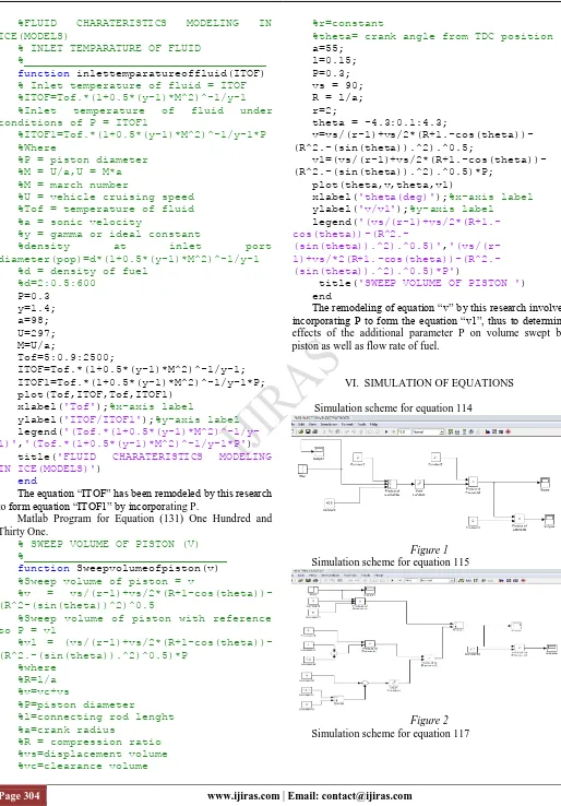
The equation “ITOF” has been remodeled by this research to form equation “ITOF1” by incorporating P.
Matlab Program for Equation (131) One Hundred and Thirty One.
% SWEEP VOLUME OF PISTON (V) %_______________________________
function Sweepvolumeofpiston(v)
%Sweep volume of piston = v
%v = vs/(r-1)+vs/2*(R+1-cos(theta))-(R^2-(sin(theta))^2)^0.5
%Sweep volume of piston with reference to P = v1
%v1 = (vs/(r-1)+vs/2*(R+1-cos(theta))-(R^2.-(sin(theta)).^2)^0.5)*P
%where %R=l/a %v=vc+vs
%P=piston diameter
%l=connecting rod lenght %a=crank radius
%R = compression ratio %vs=displacement volume %vc=clearance volume
%r=constant
%theta= crank angle from TDC position a=55;
l=0.15; P=0.3; vs = 90; R = l/a; r=2;
theta = -4.3:0.1:4.3;
v=vs/(r-1)+vs/2*(R+1.-cos(theta))-(R^2.-(sin(theta)).^2).^0.5;
v1=(vs/(r-1)+vs/2*(R+1.-cos(theta))-(R^2.-(sin(theta)).^2).^0.5)*P;
plot(theta,v,theta,v1)
xlabel('theta(deg)');%x-axis label
ylabel('v/v1');%y-axis label
legend(
'(vs/(r-1)+vs/2*(R+1.-
cos(theta))-(R^2.-(sin(theta)).^2).^0.5)',
'(vs/(r-
1)+vs/*2(R+1.-cos(theta))-(R^2.-(sin(theta)).^2).^0.5)*P')
title('SWEEP VOLUME OF PISTON ')
end
The remodeling of equation “v” by this research involves incorporating P to form the equation “v1”, thus to determine effects of the additional parameter P on volume swept by piston as well as flow rate of fuel.
VI. SIMULATION OF EQUATIONS Simulation scheme for equation 114
Figure 1 Simulation scheme for equation 115
Page 305 www.ijiras.com | Email: [email protected] Figure 3
Simulation scheme for equation 118
Figure 4 Simulation scheme for equation 131
Figure 5
VII. MODELING RESULTS
Modeling results of equation 114
Modeling results of equation 115
Modeling results of equation 117
Modeling results for equation 118
Modeling results for equation 131
VIII. SIMULATION RESULTS
Simulation result i for equation 114
Simulation result ii for equation 114
Simulation result i for equation 115
Simulation result ii for equation 115
Simulation result i for equation 117
Simulation result ii for equation 117
Simulation result I for equation 131
Simulation result ii for equation 131
IX. ANALYSIS OF RESULTS
Page 306 www.ijiras.com | Email: [email protected] These two lines are analyzed to deduce the effects of these
parameters on temperature as well as rate of fuel injection through nozzle with respect to ICE operational conditions. Simulation results ii for the equations are results obtained after incorporation of the parameters in these models.
Modeling result for equation 114 indicates that fuel velocity at nozzle tip has reduce which means that temperature effect has also reduce, hence less fuel consumption rate. From equation 115 modeling results, there is relative increase of heat from ICE. Therefore total engine temperature will be lower resulting to less fuel consumption rate. Modeling results of equation 117 indicated that injection dynamic of fuel in lower, thus fuel injection rate is lower at lower temperatures after incorporation of these parameter. Remodeling results of equation 118 reveal that intake or inlet temperature of the fuel has reduced comparatively due to the engine parameter influence. Thus, this decreases heat generation, inlet fuel temperature and total temperature of ICE. Relatively, there is reduction in piston swept volume of fuel indicated by results of equation 131. This means that the parameter influence will cause temperature reduction and piston swept volume of fuel to be consumed.
Simulation results ii for equations 114, 117, 118 and 131 show that these parameters have comparatively reduced temperature as well as rate of liquid fuel consumption after re – simulation. There is comparatively more heat release from ICE after re – simulation of equation 115. This means that total temperature of ICE was reduced likewise rate of fuel consumption.
X. CONLUSION AND RECOMMENDATION These parameters have lower total engine temperature as well as rate of fuel consumption after the re-modelings and re - simulations. Therefore, more research must be done using other methods and parameters.
REFERENCES
[1] Amini, A., Mirzaei, M. and Khoshbakhti, S. R. (2013) “Optimization – base Non – Linear Control Law with Increased Robustness for Air Ratio Control in SI Engine”. International of Automotive Engineering.
[2] Baik, S. (2001). Development of Micro – Diesel Injector Nozzles via MENS Technology and Effects on Spray Characteristics. PhD Dissertation, University of Wisconsin – M, U. S. A.
[3] Bishop, J., Nedungadi, A., Ostrowski, G., Surampudi, B. J., Armiroli, P. and Taspinar, E. (2007). “An Engine Start/Stop System for Imrove Fuel Economy”. Journal for Society of Automotive Engineers, 01 – 1777.
[4] Clive, L. (2007). “One Dimentional Modeling of an Internal Combustion Engine”. Mekanik fordjupning. [5] Gilat, A. (2004). MATLAB: An Introduction with
Applications. John Wiley and Sons (Publisher).
[6] Goldwine, G. (2008). The Effect of Fuel Injection Profile on Diesel Engine Performance, PhD Thesis Ben – Gurion University
[7] Guzzella, L. and Onder, C. H. (2010). Introduction to Modeling and Control of Internal Combustion Engine Systems. 2nd Edition, Springer Verlag, Berlin.
[8] Highm, D. J. and Higham, N. J. (2005). MATLAB Guide, 2nd Edition. Siam (Publisher).
[9] Jarrier, L., Champoussin, J. C., Yu, R. and Gentile, D. (2000). “Warm – Up Direct Injection Diesel Engine, Experimental and Modeling”. Journal for Society of Automotive Engineers. 01 – 0299.
[10] Kumar, P. R., Srinivas, P. N., Nelson, J. E. B. and Rao, S. S. (2004). “Experimental Studies on Energy Approximation in a Single Cylinder Diesel Engine”. Institution of Engineers (India) J - MC. Volume 85, pp. 45 49.
[11] Martinez, S., Sanchez, F., Bermndex, V. and Riesco – Avila M. J. (2010).
[12] Meyer, J. (2007). Engine Modeling of an Internal Combustion Engine. PhD Thesis, Ohio State University. [13] Moler, C. B. (2004). Numerical Computing with
MATLAB. Siam (Publisher).
[14] Morrison, J. and Crossland, B. (2000). An Introduction to the Mechanics of Machines. Longman Group Limited (Publisher), Essex, UK. 4th Edition, pp. 5 – 192.
[15] Nam, E. K. and Giaanneli, R. (2005). “Fuel Consumption Modeling of Conventional and Advanced Technology Vehicles in the Physical Emission Rate Estimator (PERE)”.EPA 420 – P – 05 – 001, Washington DC. [16] Pulkrabek, and Willard, W. (2004). Engineering
Fundamental of the Internal Combustion Engine. Pearson Prentice Hall (Publisher), Upper Saddle River, New Jesey.
[17] Saris, M. and Philips, N. (2005). “Computer Simulation Engine Performance”. University of Pennsylvania Press. [18] Song, G. and Yu, L. (2009). “Estimation of Fuel
Efficiency of Road Traffic by a Characterization of VSP Speed Based on Force”. Transportation Research Board, Washington, DC, pp. 11 – 20.
[19] Su, H., Mosbach, S., Bhave, A., Kook, S., Bae, C. and Kraft, M. (2007). “Two – Stage Fuel Diesel Injection of a Diesel Fuel HCCI Engine”. Journal for Society of Automotive Engineers.
[20] Tong, H., Hung, W. and Cheung, C. (2000). “On – Road Motor Vehicle Emissions and Fuel Consumption in Urban Driving Conditions”. Journal on Air Waste Management Association, volume 50, pp. 543 – 554.
[21] Vujanovic, M. (2010). Numerical Modeling of Multiphase Flow in Combustion of Liquid Fuel. Doctoral Thesis, University of Zagreb.
[22] Wu, Y. Y., Chen, B. C., Hsieh, F. C. and Ke, C. T. (2009). “A Study of the Characteristics of Fuel – Film Dynamics for Four Stroke Small – Scale Spark – Ignition Engine”. Journal for Society of Automobile Engineers, paper 2009, 01 - 0591
[23] Xin, J., Uludogan, A. and Reitz, R. D. (2004). “Exploring the Use of Multiple Injectors and Split Injectors to Reduce DI Diesel Engines Emissions”. Engine Research Center, University of Winconsin, Madison (Publisher) [24] Yue, H. (2008). Mesoscopic Fuel Consumption and
Page 307 www.ijiras.com | Email: [email protected] [25] Zheng, M., Reader, G. T. and Hawley, J. G. (2004).