A DOCUMENT MANAGEMENT SYSTEM MODELING
Ptracu AureliaPetroleum and Gas University of Ploieúti, Economics Sciences Faculty, [email protected]
Tnsescu Ana
Petroleum and Gas University of Ploieút, Economics Sciences Faculty, [email protected]
The authors propose in this paper a model for a document management system, describing, briefly, the document management system and the model concepts, as well as, the Unified Modeling Language characteristics. Finally, they are presented some more important diagrams of this language.
Key words: Model, Document Management System, UML, Class Diagram, Use Case Diagram
Introduction
Business processes streamlining and productivity increasing are fundamental concerns for any organization (private, public or non-profit) [10]. In an increasingly strict regulatory environment, the document and records management is one of the major objectives of any organization.
The electronic document management has represented a continuous concern for computer scientists from all over the world and has developed as an important activity in the document archiving and retrieving field in the documentation centres. Although, almost all the documents from an organization are electronic documents, they can not be effectively used if they are not integrated into a management system. The present technologies, both hardware and software technologies, allow the presentation of the electronic document management concept in a new context, the collaboration and cooperation context in a knowledge based economy. The document management term is a part of a wider concept that covers the communication and knowledge management aspect of an organization [6].
The document management is an information system that allows the transfer, the storage and the retrieving of any electronic documents with connecting facilities with other information systems or electronic devices [1]. In the figure 1 it is presented the document management life cycle.
Manage
Change
Create
Review
Approve
Release
Access
The authors propose in this paper a model for a document management system (DMS). For that purpose, they are defined, briefly, the DMS and the model concepts, they are described the UML language characteristics and, finally, they are presented some more important diagrams of this language.
UML characteristics
The model is an abstract representation of a system that allows system performances planning, study, analysis, conception and control before its proper achievement, as well as, the design documentation creation, facilitating at the same time the communication between the design teams [3]. This model construction implies using of a modeling language, i.e. a communication mean for all the persons involved (designers and users) to understand the same thing.
Currently, the object modeling industrial standard is UML (Unified Modeling Language). UML is a fundamental graphic language that is defined round three diagrams categories, each of them being used in representation of some information system particular concepts. The first category describes the functional services, the second one represents the system static structure and the third one refers to the dynamics of the system running [4].
UML is the standard language for specifying, visualizing, constructing and documenting the artefacts of a software system [8].
UML – a specifying language
In the software engineering, the specification means to elaborate precise, complete and without ambiguities models. A visual specification, such as UML specification, is exposed to the risk of generating ambiguities in the communication process in a higher degree than the formal specification. However, a visual specification of the solution in all the software system development stages is preferred due to the importance of better communication between the software engineering specialists (users and beneficiaries) as partners in the same project [2].
UML – a visualizing language
UML emphasizes the visualizing of a software solution to remove the biggest part of the communication problems that can arise between different participants’ categories at a software development [2].
UML – a constructing language
The models elaborated in UML can be easily translated in numerous programming languages. This state of things suggests the natural mapping possibility of a model in languages like Java, C++, Visual Basic etc. [2].
UML – a documenting language
A real software company produces all kind of components additional to executable code obtaining of a software system like [2]:
• requirements regarding software system; • system architecture describing;
• design specifications; • source code;
• development plans etc.
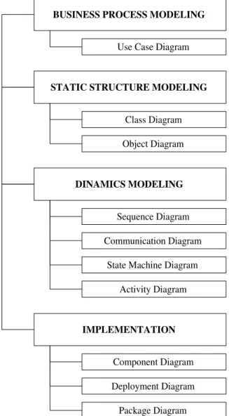
Fig. 2 UML Diagrams.
The current version (UML 2.0) adds three more diagrams: composite structure diagram, interaction overview diagram and timing diagram.
The functional model is represented in UML by the use case diagrams that describe the system from the user point of view [7].
The object model is represented in UML by the class diagrams and object diagrams that describe the BUSINESS PROCESS MODELING
Use Case Diagram
STATIC STRUCTURE MODELING
Class Diagram Object Diagram
DINAMICS MODELING
Sequence Diagram Communication Diagram
State Machine Diagram Activity Diagram
IMPLEMENTATION
Component Diagram Deployment Diagram Package Diagram
The authors presents, further, the Use Case Diagram and the Class Diagram regarding the DMS.
The Use Case Diagram produces a first view upon the system structure, a design point of departure, an identification of the objects and sequence diagrams [3]. This diagram’s elements are: the actors (interns, externs, subsystems), the use cases and the relations between use cases.
The Use Case Diagram proposed by the authors is presented in figure 3.
Fig.3 The Use Case Diagram.
In the case of DMS, the actors, i.e. the roles which the users are playing with the respect to the system, are: the system administrator, the database operator, the database and the document.
The use cases contains a set of actions sequences indicating what must be designed (conversion, document saving, deny saving).
The Class Diagram is the most important diagram in the object-oriented analysis and design. The diagram’s purpose is to structure the static nature of the classes in terms of attributes, operations and
relationships [5].
This contains classes and relationships between classes. A class is a model for objects with similar structure, behaviour and relationships. Each class has a name, attributes and operations.
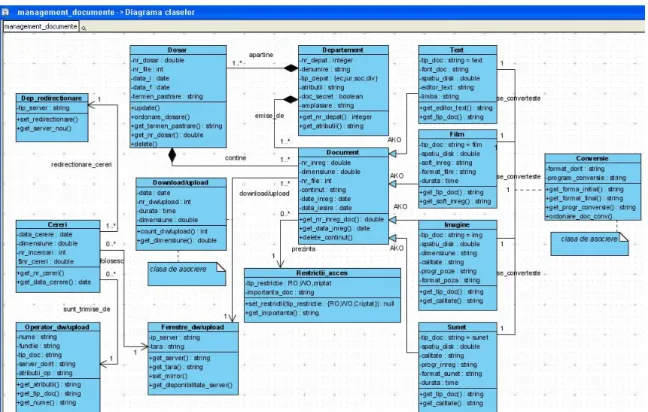
Analysing the activity regarding the document management, the authors have identified and defined 8 object classes : the existing documents (Document), the departments that issued the documents (Departament), the files in which are the documents are included (Dosar), the access restrictions (Restrictii_acces), the downloading or uploading mirrors (Ferestre_dw/upload), the access requests (Cereri), the redirecting departments (Dep_redirectionare), the operators (Operator_dw/upload) and 4 subclasses regarding the document type (Text, Film, Imagine, Sunet). There are, also, 2 special classes Conversie and Download/upload that are association classes (figure 4).
Fig. 4 The Class Diagram.
A Class Diagram can contain both relationships between classes and relationships between classes’ instances.
Relationships between classes are represented by generalization, dependency and realization. The diagram from this paper includes only generalization relationships. Generalization is a subclass-class relationship. According with the figure, in the diagram there are 4 generalization relationships between Document superclass and Text, Film, Imagine and Sunet subclasses (any instance of the Text, Film, Imagine and Sunet subclasses is, also, an instance of the Document class, inheriting the attributes and operations of this class).
Conclusions
The authors have realized a model for DMS using UML language. The UML language has the following advantages:
• is easy to use by the users; • ensures extensibility;
• formulates specifications independent of a certain programming language and system working processes.
References
1. Baltac, V., Managementul documentelor – Introducere,
http://www.softnet.ro/library/files/papers/Introducere_in_DRT.pdf.
2. Bocu, D., IniĠiere în modelarea obiect orientată a sistemelor soft utilizând UML, Editura Albastră, Cluj Napoca, 2002.
3. Dumitraúcu, L. (coord.), Analiza úi proiectarea orientată obiect a sistemelor informatice cu UML, Editura UniversităĠii din Ploieúti, 2005.
4. IoniĠă, A.D., Modelarea UML în ingineria sistemelor de programare, Editura BIC ALL, Bucureúti, 2003.
5. Lungu, I., Sabău, Gh., Velicanu, M., Sisteme informatice. Analiză, proiectare úi implementare, Editura Economică, Bucureúti, 2003.
6. Năstase, P, Managementul electronic al documentelor,
http://www.doctorat.ase.ro/Suport_curs_Modul2/Management%20elect%20documentecontabile.p df.
7. Pavelescu, R.M., Metodologie de proiectare a unui sistem de gestiune úi arhivare electronică a documentelor, Revista Informatica Economică, Editura INFOREC, Bucureúti nr. 2(26), 2003. 8. Quatrani, T., Introduction to the Unified Modeling Language, UML Evanghelist, 2003,
ftp://ftp.software.ibm.com/software/rational/web/whitepapers/2003/intro_rdn.pdf.
9. Yao, Y.-H., Trappey, A.J.C., Ho, P.-S., XML-based ISO9000 electronic document management system, Robotics and Computer-Integrated Manufacturing, Elsevier Science, vol 19, issue 4, August 2003.
10. * * *- Document Management Overview. A guide to the benefits, technology and implementation
essentials of digital document management solutions,
http://www.laserfiche.com/docs/pdf/document_management_guide.pdf.
11. * * *- Conspectus the IT report for directors and decision makers, Workflow, Document & Business Process Management, July 2004, http://www.conspectus.com
12. * * *, Visual Paradigm for Unified Modeling Language: VP-UML 6.1 User’s Guide,