The Network Layer—
Layer 3
Now it is time to hijack the GSM freight train, to see what is inside, to break into the time-slotted boxcars and spill the drums of unknown acids and solvents on the ground, to free the circus animals from their cages, and to pry loose the carefully marked and numbered boxes and bags from their neat and orderly framed pallets. Then we will paw through the letters, tear open the neatly addressed and numbered envelopes, and read through the private matters inside. It is time to dig deep into the freight and leave the carefully packed contents strewn on the side of the tracks so that we can regard the goods in all their details. In doing so, we will notice that everything was packed neatly and carefully, one box inside another. While we are engaged in our vandalism, we are careful to leave the passengers and their bags undisturbed; our interest lies only with the signaling freight, not the paying passenger traffic. The network layer (Layer 3) is the valuable freight in the GSM freight train, and the passengers are the traffic.
The network layer in the GSM architecture, also referred to as thesignaling layer,uses a protocol that contains all the functions and details necessary to establish, maintain, and then terminate mobile connections for all the services offered within a GSM PLMN. The network layer also provides control functions to support additional services such as supplementary services and short message services. Due to the complex forms of signaling, particularly those introduced by a mobile user, the GSM signaling system needs thoroughly defined procedures and structures for the protocol to be implemented reliably in the network layer [1]. This chapter will describe the
structure of Layer 3, which can be divided further into threesublayers.The general procedures of the Layer 3 protocol are introduced, as well as the parameters and the elements of a Layer 3 message. For better practical understanding, an example is offered on how Layer 3 signaling messages are exchanged during the process of setting up a call over the radio interface.
Layer 1 is the freight train, switches, lights, and tracks. Layer 2 is the pallets, boxes, drums, and carefully labeled envelopes in the train. Layer 3 is the valuable contents of all the containers and envelopes themselves. Please do not confuse the layered protocols with the speech traffic; the user’s speech data donotmove within the secure confines of the signaling layers.
7.1 SUBLAYERS OF LAYER 3
As mentioned above, there are three sublayers defined for Layer 3: (1)radio resource management(RR), (2)mobility management(MM), and (3)connection management (CM). A sublayer can be regarded as an entity unto itself, which handles the tasks and functions of a specific segment of signaling in the GSM PLMN. Its protocol consists of messages and procedures that allow each sublayer to fulfill the tasks assigned to it.
7.1.1 Radio Resource Management Sublayer
The tasks covered in this segment of the network layer are closely connected to the physical layer. The RR sublayer is responsible for the management of the frequency spectrum, the GSM system’s reactions to the changing radio environment, and everything related to maintaining a clear channel between the PLMN and the mobile station. These responsibilities include channel assignment, power-level control, time alignment, and handover from one cell to another. The RR sublayer handles all the procedures necessary to establish, maintain, and release dedicated radio connections. Appropriately, the radio connections are also called RR connections. An RR connec-tion is necessary in order to provide a path for further signaling traffic and then, eventually, a suitable traffic channel to carry the user’s data.
Within the RR sublayer, we find some carefully defined procedures used to cover these tasks:
• Channel assignment procedures; • Channel release;
• Channel change and handover procedures;
• Change of channel frequencies, hopping sequences (hopping algorithms), and frequency tables;
• Power control and timing advance;
• Modification of channel modes (speech and data); • Cipher mode setting.
A fixed network has no equivalent of the RR sublayer, because it has perma-nently wired connections to each of its subscribers, who gain access to it by simply lifting the receiver on the phone.
7.1.2 Mobility Management Sublayer
The MM sublayer has to cope with all the effects of handling a mobile user that are not directly related to radio functions. These tasks include the kinds of things a fixed network would do to authorize and connect a user to a fixed network, which are modified to account for the fact that the user may not remain in the same place:
• Support of user mobility, registration, and management of mobility data; • Checking the user and the equipment identity;
• Checking if the user is allowed to use the services and what kind of extra services are allowed;
• Support of user confidentiality (registering the user under a temporary mobile subscriber identity (TMSI));
• Provision of user security;
• Provision of an MM connection, based on an existing RR connection, to the CM sublayer (see Section 7.1.3).
The MM sublayer uses a large number of predefined procedures to meet the needs listed above:
• Location update procedure. • Periodic updating.
• Authentication procedure.
• IMSI attach procedure. A mobile station will perform (when indicated by the attach flagin the base station’s BCCH) a location update procedure after power-on, present its IMSI to the network, and get a TMSI in return.
• IMSI detach procedure. A mobile station will perform (when indicated by the attach flag in the base station’s BCCH) adetach procedure just after power-off, telling the network that it is no longer in service.
• TMSI reallocation procedure. • Identification procedure.
7.1.3 Connection Management Sublayer
The CM sublayer manages all the functions necessary for circuit-switched call control in the GSM PLMN. These functions are provided by the call control entity within
the CM sublayer. There are other entities within the CM sublayer to cope with providing supplementary services and SMSs. The call control responsibilities are almost identical to those provided in a fixed network; the CM sublayer is virtually blind to the mobility of the user. The call control access schemes used in GSM are, to a large degree, inherited from the ISDN, with only a few simplifications and adaptations. The call control entity in a GSM network establishes, maintains, and releases call connections for communication links. Again, there are some specific procedures defined for this purpose:
• Call establishment procedures formobile-originated calls; • Call establishment procedures formobile-terminated calls;
• Changes of transmission mode during an ongoing call (incall modification); • Call reestablishment after interruption of an MM connection;
• Dual-tone multifrequency (DTMF) control procedure for DTMF transmissions. Note: Two low-frequency tones within the audible frequency range from a 4
×4 matrix can represent any one of 16 depressed dial keys. This DTMF dial method is used in the U.S. fixed telephone network, in contrast to the pulsed dialing used in so many other places. The analog transmission of such tone sequences can also be used to access certain supplementary services in the network (e.g., to check a mailbox or enable call forwarding to another number). GSM is a digital network, and digital values (bits) have to be transmitted instead of analog binary representa-tions such as tones.
A call control connection is always based on an existing MM connection. The call control entity uses the MM connection to exchange information with its peer.
7.2 STRUCTURE OF A LAYER 3 MESSAGE
Before taking a closer look at a typical signaling sequence, let us see what the process should do. A signaling process may contain one or more signaling procedures, and each procedure consists of an exchange of signaling messages. A signaling message is, however, not the smallest unit we can consider when dividing signaling procedures into their constituent parts. A signaling message consists of elements, and each element has a specific purpose, function, and information content.
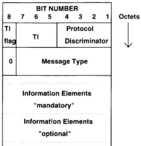
Figure 7.1 shows a schematic view of the structure of a Layer 3 message. Note the similarity to the Layer 2 envelope in which this message will eventually be placed. The information contained in the message, and its binary representations (each octet of eight bits), is the Layer 3 part that goes into the Information field of a Layer 2 frame.
Only theoptionalandmandatoryinformation elements of the Layer 3 message have a variable length, indicated with the dotted lines in Figure 7.1. All the elements of the message are explained in the following four sections.
Figure 7.1 Structure and elements of a Layer 3 message.
7.2.1 Transaction Identifier
The transaction identifier (TI) is a pointer with a length of four bits. It is used to distinguish between (possible) multiple parallel CM connections and between the various transactions taking place over these simultaneous CM connections. For RR and MM connections, the TI is not relevant; the TI field is always coded with 0000 in these cases. The TI uses the bits 8-7-6-5 in the first octet of a Layer 3 message. Bit number 8 is called theTI flagand indicates the originator of a CM connection. It is set to 0 by the originator of a CM message, and when a message is sent back to the originator by its peer entity, it is coded with a 1. The originator also fills in theTI value(bits 7, 6, and 5). The TI value is kept for the duration of a transaction and serves as a label for it.
7.2.2 Protocol Discriminator
The protocol discriminator (PD) links the Layer 3 protocol to the entity the message is addressed to. It has a length of four bits, and it identifies the six protocols shown in Table 7.1.
Table 7.1
Protocol Discriminators Used in GSM Signaling
Protocol PD Binary PD Hexadecimal
Radio resources mgmt. 0 1 1 0 6 Mobility management 0 1 0 1 5 Call control 0 0 1 1 3 Short-message service 1 0 0 1 9 Supplementary service 1 0 1 1 B Test procedure 1 1 1 1 F All other values are reserved
7.2.3 Message Type
The message type (MT) indicates the function of the Layer 3 message. It uses the lower six bits of the second octet in the Layer 3 message. Six bits are sufficient to address 64 different message types in a protocol indicated by the PD. The MT is part of a set of messages in a protocol. Bit 8 is reserved and is always set to 0. Bit 7 is a send sequence variable and may be used for MM and CM messages.
7.2.4 Information Elements
A Layer 3 message may contain one or more information elements (IE). Whether or not there are IEs, and how many IEs are contained in a message, depends on the MT. There are distinct definitions for the different MTs, each of which decides which IEs (if any) must or may be present in a message. GSM distinguishes mandatory IEs, which appear earlier in a message and have a reserved place in the structure of the message, from optional IEs. Optional IEs, if present, appear after the mandatory IEs. Optional IEs always have to carry aninformation element identifier(IEI), which tells the receiver of the message the purpose of the information contained therein.
Another distinction can be made between IEs with fixed and variable lengths. IEs with variable lengths also have to carry a length indicator, which is one octet. The length indicator is not to be confused with the length indicator field in a Layer 2 frame.
There are, then, four possible combinations of IE types: 1. Mandatory fixed length (MF);
2. Mandatory variable length (MV); 3. Optional fixed length (OF); 4. Optional variable length (OV).
7.3 EXAMPLE OF A LAYER 3 MESSAGE
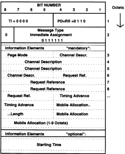
The structure and functions within a message can be illustrated with a complete signaling message. The example chosen is animmediate assignmentmessage, which
is sent on the AGCH by a base station in response to an initial channel request (random access burst) from a mobile station. Its purpose is to assign a dedicated channel for a continuing signaling procedure. It is, itself, part of an initial channel assignment procedure, which is performed in order to establish an RR connection. Figure 7.2 shows the content of an immediate assignment message.
The immediate assignment message contains most of the information the mobile station needs to establish an RR connection with the network. This information is contained in the IEs of the message. The reader should note that the mandatory IEs
appear before the optional IEs, the ones with a fixed length before the ones with variable length. The message, including all the fixed-length fields at its start, are eventually mapped into the Information fields in an appropriate Layer 2 frame.
The mobile station may request a channel for various reasons. Some of the reasons are (1) establishing a call after being paged, (2) establishing a call after the user has dialed a number and pressed the SEND button, and (3) performing a location update procedure.
The TI has the value 0000, because the immediate assignment belongs to the RR protocol (the PD indicates this; see the first entry in Table 7.1). The MT is followed by the mandatory and optional IEs. Six IEs are examined here.
7.3.1 IE Page Mode
The page mode informs the mobile station how and with which paging blocks within the PCH it will still have to monitor the network. The PCH configuration on the broadcast channel is subject to change due to different loads on a base station. The IE page mode consists of only half of an octet (four bits).
7.3.2 IE Channel Description
The IE channel description contains all the necessary information about the physical dedicated channel identified in this initial assignment.
1. Channel type: Five bits are used to indicate the channel type, including a subchannel number, if applicable (e.g., FACCH/TCH, SDCCH/4, SDCCH/8). The applicable bit patterns are:
00001 for FACCH/TCH;
0001T for half-rate FACCH/TCH (when half-rate is introduced); 001TT for SDCCH/4 or CBCH (cell broadcast for short messages) on
SDCCH/4;
01TTT for SDCCH/8 or CBCH (cell broadcast for short messages) on SDCCH/8.
The T-bits indicate the subchannel number. The bit pattern 01010 would indicate an SDCCH/8 (01 binary = the fourth channel type), subchannel 2 (010 binary=2 decimal).
2. The time slot number: Three bits address the time slot number to be used on the assigned channel, and the range is from 0 to 7.
3. The training sequence code (TSC): Three bits indicate the TSC to be used on the assigned channel. There are eight different TSCs defined, and they range in from 0 to 7.
4. The hopping bit: The hopping bit indicates whether frequency hopping should be used.
5. The mobile allocation index offset (MAIO) and the HSN: In the case of frequency hopping, these two parameters inform the mobile stations of the channels to hop among and which hopping sequence to use.
6. The ARFCN: In the case where no frequency hopping is to be used, this parameter defines the channel number of the newly assigned channel.
7.3.3 IE Request Reference
This IE consists of three octets. It contains the five-bit random number, which was sent by the mobile station in the channel request (random access burst), and the three-bit coded cause of the channel request (eight bits total). Two more octets are used to tell the mobile station at which frame number the channel request (in the mobile’s random access burst) was received by the base station. The mobile’s channel request is answered by this particular immediate assignment message. This little trick makes it possible for the mobile station to identify its own unique immediate assignment message after sending only eight information bits. The mobile station knows the random number, and it knows the frame number in which it sent the channel request. The problem of more than one mobile station accessing the same channel because of reading the same immediate assignment message is solved with a rather high probability of success with this trick.
7.3.4 Timing Advance Value
The first correction value for the mobile station’s burst timing is sent in the first dedicated message to a terminal. The base station derives this value from the timing error in the random access burst it receives from the mobile station. The first timing correction makes sure that the next burst from the mobile station fits into the assigned time slot (see Section 7.3.2, item 2). Additional timing advance adjustments are contained in the SACCH, which is sent along with any dedicated channel (SDCCH or TCH/FACCH).
7.3.5 IE Mobile Allocation
When it comes time to assign a dedicated channel with frequency hopping, this IE assigns the frequency channel numbers to be used in the hopping sequence. The selection is a subset (maximum: all) of the frequency channels used by the base station in a cell or a cell sector. This IE has a variable length of from one to nine octets.
7.3.6 IE Starting Time
The only optional IE in the immediate assignment message has a length of three octets, including the IEI. It is used to tell the mobile station a frame number. The mobile has to wait until the indicated frame number appears (in the T1, T2, and T3 timers) before it can start further transmissions. The maximum time covered by this IE is a little more than three minutes.
7.4 EXAMPLE OF A SIGNALING PROCESS: CALL ESTABLISHMENT
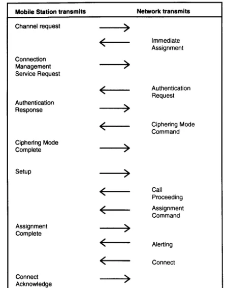
A number of signaling messages have to be exchanged between a mobile station and a base station in order to establish a call connection over the radio interface. The base station is the element in the GSM network the mobile stationtalksto. However, most of the signaling messages in the downlink (from the base station to the mobile station) do not originate in the base station (BTS) itself, but originate further back in the network, usually from the BSC or the MSC. Some signaling messages originate in the mobile, and most uplink signaling messages are directed to the entities behind the BTS, as well. The BTS only transports the messages between the data link layer and the physical layer; it acts as a bit mapping device as it transforms the Um bit sequences to the Abis bit patterns. The BTS can make the reverse transformation as well. Figure 7.3 shows the signaling flow exchanged during amobile-originated call setupin the form of MTs. Mobile users dial the number they want to reach and then push the SEND button on the phone. The mobile station, of course, has to be registered to and synchronized with the network before it can indicate service availability on its handset display. Figure 7.3 shows that 14 messages are required to activate a traffic channel, but this signaling flow takes place within just a few seconds. The actual duration of this signaling sequence is strongly dependent on the logical channel used for information transfer.
The mobile station starts with the transmission of achannel requestmessage (random access channel) for the remainder of its signaling needs. The immediate assignment message assigns the requested signaling channel (see Section 7.3 for some of the details). Once it is assigned to a dedicated channel, the mobile station tells the network what it desires, in this case the services of the CM entity. It transmits aCM service requestmessage to make its wishes known to the network. Before this service can be granted, some RR matters and some MM procedures have to be sorted out. We have already learned that a call control connection or a CM connection will be based on existing RR connections and MM connections. The necessary connections are established by the authentication procedure (authentication request andresponse) and the subsequent RR procedure, which sets the cipher mode (cipher mode commandandcipher mode complete). The authentication response will contain a key that the network uses to verify the mobile station’s authorization to obtain
Figure 7.3 Example of a call establishment sequence.
service. The cipher mode command is used by default in this procedure in order to switch on an encryption process in Layer 1. It is, however, also possible that the cipher mode command indicates that no ciphering is used. Ciphering would start with the transmission of the cipher mode complete message, which will already be encrypted. Then the mobile station will transmit the setupmessage indicating the
type of service it requires from the CM entity, the user number it would like to reach, and (optionally) identification of itself and its capabilities. The network starts a routing process in order to connect the addressed user (signaled bycall proceeding). In the meantime, the network assigns a traffic channel for the transmission of user data (speech). This assignment command is answered by an assignment complete message from the mobile, which is already on the new channel (TCH/FACCH) and is using the FACCH for the remaining signaling messages. The old signaling channel is released and this resource is made available for other signaling links. When the other party is reached and alerted (the phone rings), the network transmits thealert message to the mobile. The mobile station generates an audible ring-back tone to tell its user that the other party has been reached and is being alerted. There are also some procedures defined in case the other party is busy or cannot be reached at all. In the successful case, the other party will accept the call by lifting the receiver, which is indicated by theconnect messageto the mobile. The acknowledgment by the mobile station is accomplished with theconnect acknowledge message it sends back to the network. The FACCH, which was used for the final signaling messages, is replaced by user data.
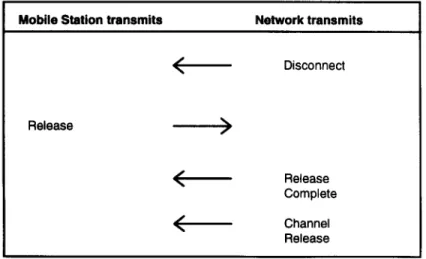
In order to disconnect the communication link, such as would happen if the land party hangs up, the network will initiate a call release procedure by sending a disconnect message (see Figure 7.4). This message will be followed by a release message from the mobile station. The network acknowledges this with a release completemessage. Then comes the transmission of thechannel releasemessage after which the Layer 3 connection is terminated. The data link layer connection will also
be disconnected (see Chapter 6), and, finally, the physical radio link will vanish. Figure 7.4 shows the procedure of a network-initiated call release.
There are some defined procedures for a call setup originated by the network (paging) and a mobile-originated call release. There are also mechanisms to be called upon when problems arise during the signaling processes. These mechanisms generally bring the signaling entities back into a defined state in order to avoid tied-up network resources, wasted capacity, and bad service. Such mechanisms include the repetition of messages that were not answered or ignoring bad or incomplete messages, or they may simply release the whole signaling link.
7.5 A LAYER 3 SIGNALING TRACE
A call setup recorded by the same GSM test system we used in Chapter 6 will illustrate the exchange of signaling data over the radio interface (Figure 7.5). This time we ignore the Layer 2 envelopes and look only at their contents. The procedure is a mobile-originated call setup that a GSM mobile station has performed in a network simulated by the test system.
In a manner similar to the Layer 2 trace (in Section 6.4), the test system has added some information that is useful when examined in combination with the exchanged messages. The information includes frame numbers, time stamps, the direction of transmission (uplink=ul, downlink=dl), the logical channel (RACH/ AGCH/SDCCH/FACCH), time slot number, TI, PD, as well as MTs, IE names, and their contents. The T1, T2, and T3 counters appear just as they did in Chapter 6.
The trace used an SDCCH/8 signaling channel. We can also look at the TDMA frame numbers to determine how long the whole procedure lasted.
FN start (channel request): 4,610
FN connect: 5,386
Difference: 776
Since the duration of one TDMA frame is 4.615 ms, the duration of the whole signaling sequence is 4.615 ms/frame×776 frames=3.58 seconds.
7.6 TIMERS
In order to ensure a smooth flow of signaling messages and to avoid tied-up links or the excess use of processor time and network (radio channel) capacity, there have to be restrictions on the time used for the procedures. There also have to be restrictions on the number of attempts made to perform certain signaling procedures. A mobile station that continuously transmits channel requests, even when a base station
Figure 7.5 (continued).
rarily has no capacity to serve it, would disturb the network and generate unnecessary radio traffic. This negative effect can be controlled and managed by the use of additional timers. The GSM network and its entities work with a number of timers in the signaling processes. A timer is started at the transmission of a message that requires an answer within a defined period. Upon receiving the answer, the timer is stopped or reset. For example, the network side starts a timer called T3101 at the transmission of an immediate assignment message. It is reset after the mobile station transmits on the newly assigned channel. If the mobile station does not seize the new channel within this time (in T3101), the channel request will be ignored and the reserved channel will be released for another communication link. The spurned mobile station would have to request a channel again.
For the data link layer, Layer 2, a timer called T200 is defined. It specifies how long a Layer 2 entity can wait before repetition of a Layer 2 frame. An example is an SABM command not answered by a UA response. The possible response times are a function of the data rates of the different logical channels; the FACCH is much faster than the SDCCH. There are, therefore, different timer values for different logical channels. They range from 155 ms to approximately 1 second.
7.7 SIGNALING ARCHITECTURE IN A GSM PLMN
A GSM PLMN uses complex and sophisticated signaling processes to provide service and still be flexible enough to interface with a variety of communication entities and partner systems. Although a multitude of thick specifications exist, all GSM networks installed in the world and all those yet to be installed in the future will differ from each other in their architectures. This is because of the different services offered in different markets and the different access and interfaces to the fixed networks. The signaling architectures still have some common ground on which we
can work. One of the major objectives in designing the GSM system was, and remains, to maintain an open and flexible character in the architecture, leaving it open to adaptations, different interfaces, and new service implementations. The chief infrastructure components interface physically with each other (radio interface Um, Abis interface, A interface) as well as logically with each other (OSI layers and CCITT SSN7). The logical entities in a GSM PLMN have their assigned tasks and functions. They communicate with each other with protocols and procedures. They all represent a giant communications system: a huge machine, which connects and disconnects, switches and relays, routes and registers, counts and bills. Taken together with all the connecting fixed networks, it becomes the largest machine ever made. This chapter will give a general view on how a GSM PLMN logically intercon-nects from the exchange (MSC) to the user terminal (mobile station), since this subject does not belong anywhere else in the book. A complete analysis and discussion of the structures and architectures inherent in the definition of a GSM PLMN is far beyond the scope of this book. The interested reader should refer to the applicable GSM Technical Specificationsfor further details. Another, far less painful approach to discussing the subject in all its variety can be found in [2], which is recommended as an intermediate step between this book and the official standards and recommen-dations.
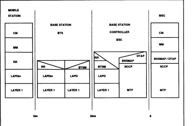
Figure 7.6 shows the GSM signaling environment in a simplified diagram with logical blocks, functional planes, and interfaces.
The are four entities (devices or machines): • Mobile station;
• Base transceiver station; • Base station controller; • Mobile switching center.
The three interfaces that connect them have names: • Um (between the mobile station and BTS);
• Abis (between the BTS and BSC); • A (between the BSC and MSC).
7.7.1 Mobile Station and Base Transceiver Station Connection
The GSM mobile station includes all Layer 3 functions and its sublayers (RR, MM, CM). It interfaces with the BTS via the radio interface, Um (Layer 1), and the LAPDm (Layer 2). LAPDm ends in the BTS. The BTS itself only needs very restricted Layer 3 capabilities. There are only a few RR functions in the BTS, where some examples are (1) to control transmission timing (timing advance) and (2) power control. The BTS is transparent to the much larger amount of signaling that comes with MM and CM.
Network
Layer—Layer
3
179
7.7.2 The BTS-to-BSC Connection
The BTS interfaces with the BSC on the Abis interface via a PCM-30 link, which is a 2.048-Mb (32 subchannels (or slots)×64 kbps=2.048 Mbps) fixed-line standard [3]. See Chapter 11 in Part III on base station testing for lots of details on the Abis interface. Due to its late and initially fragmented standardization, the Abis interface appeared in a variety of different interpretations and implementations. This led to incompatibilities among network components from different manufacturers. So, if network operators decided to buy a BSC from one supplier, they had little choice but to buy BTSs from the same supplier. The Abis interface uses 64-kbps signaling subchannels in order to carry signaling data and submultiplexed 16-kbps channels (one 64-kbps subchannel has four 16-kbpssub-subchannels) for the transfer of user data (speech). For the transformation of speech in and out of the 64-kbps links, which are used as a standard in the ISDN and GSM networks as the only entities that can be switched, a transcoder rate adapter unit (TRAU) is used. The TRAUs can be physically located in the BSC, in the BTS, or even in the MSC. This leads to a wide variety of installations. Rate adaptation is also an important issue for non-speech user data transmissions. In general, it is more economic to have the TRAU/ rate adaptation as close as possible to the switch (MSC), because the traffic adapted to the rates used in GSM radio transmission (speech: 13 kbps easily fits into a 16-kbps subchannel) is substantially lower (and thus cheaper to transmit) than the 64 kbps of fixed ISDN lines. In the case of speech traffic taking place between two users of GSM mobile stations, the signals will always be transformed twice: first from 13 to 64 kbps, and second from 64 back to 13 kbps, even if they are both connected to the same BSC or BTS.
The BSC controls the BTSs connected to it and maintains contact with the MSC. A BSC and the connected BTSs are, together, also referred to as abase station subsystem (BSS). The BSC has to perform the remainder of the RR functions and relay information, such as random access, paging, and ciphering messages.
7.7.3 The BSC-to-MSC Connection
The BSC is connected via a PCM-30 link to the MSC; this interface is called an A-interface.The switching entity of the GSM PLMN, the MSC, is organized with a CCITT SSN7 protocol. Consequently, it transmits and receives user data (speech), and signaling data in 64-kbps subchannels of the PCM-30 link (CCITT G.703, ISDN standard).
The A-interface also transmits the CM and MM protocols to and from the MSC. The BSC and BTS are transparent to these messages, which is to say they merely hand them back and forth using their own protocols and various means of physical transmission (LAPD, LAPDm, and Layer 1). The functions within the MSC
that are used to handle and convey this kind of information (meant for a specific mobile station), as well as general BSS control information, is allocated to the base station system management part (BSSMAP) and the direct transfer application part (DTAP). They make use of the lower planes’ signaling connection control part (SCCP) and message transfer parts (MTP), which are equivalent to the lower three layers in the OSI model. The SCCP is responsible for the establishment of signaling nodes, and the MTPs transfer the information between the nodes.
REFERENCES
[1] GSM Technical Specifications,ETSI, Sophia Antipolis, Vols. 04.07 to 04.88.
[2] Mouly, M., and B. Pautet,The GSM System for Mobile Communications,Palaiseau, 1992. [3] CEPT T/S 46-20 Recommendation and CCITT Q.920/921/G.703 Recommendations.