Universiteit Leiden
Computer Science
A Method for Automated Prediction of
Defect Severity Using Ontologies
Name:
Martin Pavlov ILIEV
Student-no:
s1053574
Date: 10/07/2012
1st supervisor: Dr. M.R.V. (Michel) Chaudron
2nd supervisor: Dr. P.W.H. (Peter) van der Putten
MASTER'S THESIS
Leiden Institute of Advanced Computer Science (LIACS)
Leiden University
Niels Bohrweg 1
2333 CA Leiden
The Netherlands
A Method for Automated Prediction
of Defect Severity Using Ontologies
Martin Pavlov ILIEV
Master’s Thesis
LIACS, Leiden University
Logica Netherlands B. V.
ABSTRACT
Assessing severity of software defects is essential for prioritizing fixing activities as well as for assessing whether the quality level of a software system is good enough for release. In practice, filling out defect reports is done manually and developers routinely fill out default values for the severity levels. Moreover, external factors are a reason for assigning wrong severity levels to defects. The purpose of this research is to automate the prediction of defect severity. We have researched how this severity prediction can be achieved through incorporating knowledge of the software development process using ontologies. In addition, we also employ an IEEE standard to create a uniform framework for the attributes of the defects.
The thesis presents MAPDESO – a Method for Automated Prediction of DEfect Severity using Ontologies. It was developed using industrial case studies during an internship at Logica Netherlands B. V. The method is based on classification rules that consider the software quality properties affected by a defect, together with the defect’s type, insertion activity and detection activity. The results from its validation and comparison with the Weka machine learning workbench indicate that MAPDESO is a good predictor for defect severity levels and it can be especially useful for medium-to-large projects with many defects.
ACKNOWLEDGEMENTS
I would first and foremost like to thank my academic supervisors, Dr. Michel Chaudron and Dr. Peter van der Putten, and my mentor at Logica, ir. Edwin Essenius, for their time, effort, guidance and invaluable feedback throughout the research.
Big thanks to the people at Logica for being very helpful and open-minded and for allowing me to work on industrial case studies. I also want to thank the members of the Software Engineering Group at LIACS for their useful insights and advice throughout the research. Finally, I would like to express my deepest gratitude to my family since without them none of this would have been possible. I would like to thank them for their inexhaustible support, for their patience and understanding and for encouraging me to always do the very best I can. Thank you!
- 3 -
CONTENTS
1. INTRODUCTION ... - 5 -
1.1. Problem statement ... - 5 -
1.2. Means for achieving the research goal ... - 6 -
1.3. IEEE Standard ... - 7 -
1.4. Related work ... - 8 -
1.5. Research contribution ... - 10 -
1.6. Outline ... - 10 -
2. ONTOLOGY DEVELOPMENT AND LANGUAGES ... - 11 -
2.1. Definition ... - 11 -
2.2. Ontology development and editors ... - 12 -
2.3. Web Ontology Language ... - 14 -
2.4. Reasoners ... - 15 -
2.5. Ontology editor, language and reasoner used in the research ... - 16 -
2.6. Section summary ... - 16 -
3. METHOD DESCRIPTION ... - 17 -
3.1. Developing the ontology ... - 17 -
3.1.1. Meta-meta level ... - 17 -
3.1.2. Meta level ... - 17 -
3.1.3. Class level ... - 19 -
3.1.4. Instance level ... - 22 -
3.1.5. Classification rules ... - 23 -
3.2. The method flow ... - 25 -
3.2.1. Detection of defects ... - 27 -
3.2.2. Analysis and conversion of the defects’ information ... - 27 -
3.2.3. Entering the converted information into the ontology ... - 28 -
3.2.3.1. Creating the classes for the defects – editor Create Multiple Subclasses ... - 29 -
3.2.3.2. Adding the converted information to the classes – Quick Restriction Editor ... - 30 -
3.2.4. Automatically predicting the severity levels of defects ... - 31 -
3.3. Section summary ... - 33 -
4. CASE STUDIES ... - 34 -
4.1. Case Study 1... - 34 -
4.1.1. Data collection ... - 34 -
- 4 -
4.1.3. Data classification ... - 35 -
4.1.4. Results ... - 36 -
4.2. Case Study 2... - 38 -
4.2.1. Data collection ... - 38 -
4.2.2. Data analysis and conversion ... - 39 -
4.2.3. Data classification ... - 39 -
4.2.4. Results ... - 40 -
4.3. Summary of the results from Case Study 1 and Case Study 2 ... - 41 -
4.4. Section summary ... - 42 -
5. VALIDATION... - 43 -
5.1. Approach – VCS ... - 43 -
5.1.1. Data collection ... - 43 -
5.1.2. Data analysis and conversion ... - 44 -
5.1.3. Data classification ... - 45 -
5.2. Results ... - 45 -
5.3. Validation of the results ... - 47 -
5.4. Experiment ... - 47 -
5.5. Section summary ... - 52 -
6. COMPARISON ... - 53 -
6.1. The Weka machine learning workbench ... - 53 -
6.2. Predicting severity levels of defects using classifiers from Weka ... - 54 -
6.2.1. Preparing the data ... - 54 -
6.2.2. Selecting the classifiers ... - 55 -
6.2.3. Classifying the test data ... - 58 -
6.3. Comparison of the performances... - 59 -
6.4. Section summary ... - 64 -
7. CONCLUSIONS AND RECOMMENDATIONS... - 65 -
8. FUTURE WORK ... - 67 -
BIBLIOGRAPHY... - 68 -
Appendix A ... - 70 -
- 5 -
1.
INTRODUCTION
Software goes through a testing phase, which aims to find the problems users might experience before the software goes into actual use. The goal of finding these problems is to remove them before the actual use of the software so that the users will not be hindered by them. According to the IEEE Standard Classification for Software Anomalies [2], the cause of a software problem is called a software defect. In order to remove the problems, the defects need to be fixed. Within this thesis well established standards (including the IEEE Standard Computer Dictionary [1] and the IEEE Standard in [2]) are used for defining the necessary terms. The classification in [2] defines a defect as:
a fault if it is encountered during software execution (thus causing a failure);
not a fault if it is detected by inspection or static analysis and removed prior to executing the software.
In [1] a fault is defined as an incorrect step, process, or data definition in a computer program, while a failure represents the inability of a system or component to perform its required functions within specified performance requirements. The dictionary relates all these terms to one another by distinguishing between a human action (a mistake), its manifestation (a hardware or software fault), the result of the fault (a failure), and the amount by which the result is incorrect (the error). Hence, a software defect is the reason for producing an incorrect or unexpected result in a computer program or system, or it causes it to behave in unintended ways.
All users would like to have quality software products. Quality, as given in [1], represents the degree to which a system, component, or process meets specified requirements, customer or user needs or expectations. Therefore, a step towards deploying a high quality software product is to test it first. This is achieved during the system testing phase of the software development life cycle when testing is conducted on a complete, integrated system to evaluate the system’s compliance with its specified requirements [1]. This phase results in finding defects in the software product. In general, it is very difficult (or not possible at all) to fix all defects before the deployment date. Hence, these defects need to be categorized so that only the important ones are fixed within the specified time constraint in order to release a quality software product.
1.1. Problem statement
Out of all defects found during the testing phase, the important ones have to be fixed before a predefined deadline. Therefore, a software team needs to decide on the order in which to fix these defects. It is a common practice to assign severity levels to the defects to differentiate between their impacts on the software. The severities of defects represent the different levels of negative impact a defect will have on the deployment of a software product. For example, a severity level showstopper is assigned to defects that prevent the release of the software system and immediate attention is required. On the other hand, a severity level minor is
- 6 - assigned to defects that do not prevent the release of the system but the users are annoyed by their presence. It is clear, then, that defects must be assigned the correct severity levels.
The assignment of severity levels to defects is specific for every software system or company and is done manually, usually by test analysts according to their expertise. Different software projects define different sets of severities and, hence, assign different severity levels to their defects. This results in software projects using sets of severities containing three, four or five severity levels (sometimes even more). In addition, it is regularly the case that a defect is assigned the default severity level, which typically is medium. If, at this point, a user is consulted, he/she might not agree with the assignment of default severities and might want some defects to be fixed sooner than others. Moreover, people sometimes make mistakes when assigning severities or are influenced by external factors that lead to assigning wrong severity levels to defects. To address these problems, we have conducted research in the area of how to predict the severity of defects using the knowledge of the software development process while decreasing the workload of the software architects and the test analysts. This means that we use this knowledge to assign severities that reflect what is important not only for the developers but also for the users. The aim is to devise a method for automatically predicting the severity levels of defects found during testing at the system level and also during coding and maintenance. Its name is MAPDESO – a Method for Automated Prediction of DEfect Severity using Ontologies. Such a method would be especially useful for medium-to-large software systems, which have 100 defects or more.
1.2. Means for achieving the research goal The means used for achieving the goal of this research are
the IEEE standard in [2] in order to create a uniform framework for the attributes of the defects, and
Artificial Intelligence (AI) techniques, namely ontologies, reasoning and automatic classification, in order to capture software defects through an ontology and automatically reason about the defects and their severity levels.
Since different projects define and use different sets of severity levels, creating a uniform framework will be valuable for providing a single set of severity levels that is known to everybody – software architects, developers, test analysts. Therefore, the time and cost for retraining people when they switch projects will decrease since all projects will conform to the same standard for software anomalies.
In addition, researchers have used different techniques to predict the severity levels of defect reports [3], the presence or absence of faults [4] and defects [5], [6]. These techniques include standard text mining methods, logistic regression and machine learning techniques, Six Sigma methodology. Though they have proven to be very useful, they base their results on text mining analysis and on statistical methods. For achieving the research goal we use AI techniques because this way the prediction process is automated and it is based on the different levels of impact defects have on the quality properties of the software (other factors also take part in the prediction process).
- 7 - Figure 1 presents a summary of everything explained until now. The problems in the figure refer to the problems mentioned in Section 1.1; the method (explained in details in Section 3) includes the means for achieving the goal of this research as given partly in Section 1.1 and in Section 1.2, while the result is the outcome from the method as given in Section 1.1.
Figure 1. Summary of the current problems, the method to overcome them and the end result. The next subsection contains details about the above-mentioned IEEE standard while Section 2 presents details about ontologies and ontology engineering.
1.3. IEEE Standard
The IEEE Standard Classification for Software Anomalies (IEEE Std 1044™-2009) [2] is sponsored by the Software & Systems Engineering Standards Committee of the IEEE Computer Society and it was approved on 9 November 2009. This standard provides a uniform approach to the classification of software anomalies, regardless of when they originate or when they are encountered within the software development life cycle. The classification data, given in [2], can be used for a variety of purposes, including defect causal analysis, project management, and software process improvement (e.g., to reduce the likelihood of defect insertion and/or to increase the likelihood of early defect detection). Moreover, the standard contains a classification of defects, which defines a core set of widely applicable classification attributes. Sample values for the most common attributes are provided together with definitions and examples for both the attributes and their values. The table in the standard with the most common attributes and their values contains ten attributes. For the purposes of our research the attributes that provide the following information are necessary:
what is the severity of a defect (only one value is possible),
what is/are the quality property/properties affected by a defect (one or more values are possible),
what is/are the type(s) of a defect (one or more values are possible),
in which phase of the software cycle a defect was inserted (only one value is possible),
and in which phase of the software cycle a defect was detected (only one value is possible).
- 8 - Hence, the following five attributes are selected from the standard: Severity, Effect, Type, Insertion activity and Detection activity. The idea behind using specifically them is to provide a uniform framework for the attributes of the defects and their values so that the method can be used across multiple software projects and systems.
It should be noted that there are five more attributes – Status, Priority, Probability, Mode and Disposition. They also provide valuable information but it is not essential for the purposes of this research (knowing the values of these attributes for the different defects is not obligatory). Therefore, these five attributes are not considered in the rest of the research.
1.4. Related work
As explained in the previous sections, the severity levels assigned to defects are used to find out what is the impact of that defect on the deployment of the software. It is also known that different software projects assign different severity levels to their defects. More importantly, why a specific defect is assigned one severity and not another and whether both the developers of the software product and its users agree on the assignment of the severity levels are areas that still need more attention.
A new and automated method, which assists the test engineer in assigning severity levels to defect reports, is presented in the paper by Menzies and Marcus [3]. The authors have named the method SEVERIS (SEVERity ISsue assessment) and it is based on standard text mining and machine learning techniques applied to existing sets of defect reports. The tool is designed and built to automatically review issue reports and alert when a proposed severity is anomalous. Moreover, the paper presents a case study on using SEVERIS with data from NASA’s Project and Issue Tracking System (PITS). The case study results indicate that SEVERIS is a good predictor for issue severity levels, while it is easy to use and efficient. The idea behind our research is similar to the study in [3] – an automated method for predicting what severity levels to be assigned to defects. However, we base our method on the software development process and software quality properties in order to decide what severity level to assign to a defect so that, in the end, the user satisfaction with the quality of the deployed software product will rise.
Zhou and Leung [4] investigate the accuracy of the fault-proneness predictions of six widely used object-oriented design metrics with particular focus on how accurately they predict faults when taking fault severity into account. Their results indicate that most of these design metrics are statistically related to fault-proneness of classes across fault severity and that the prediction capabilities of the investigated metrics greatly depend on the severity of faults. This work is similar to the one in [3] since the authors use logistic regression and machine learning methods for their empirical investigation. In our research, we focus on predicting the severity levels of defects using AI techniques such as ontologies and automatic classification. This is achieved by developing an ontology and classifying the defects input in it using developed classification rules.
It should also be mentioned that there is research in the area of predicting defects in the design phase [5]. This research resulted in the development of a tool called MetricView. Its goal is to give more insight into UML models by visualizing software metrics that have been computed
- 9 - by an external tool directly on top of the graphical representation of the UML model. Hence, this tool makes it clearer to see what is correct and what is incorrect in the models. There is also an extension to this tool that provides a lot of additional features such as calculations of metrics within the tool, several views to explore and navigate UML models, visualization of evolution data. The research presented in [5] can be related to ours because we make use of the software process though not for predicting defects but for predicting the severity levels of the defects. An obvious difference is also the fact that we are interested in defects detected mainly from the system testing phase and not from the design phase.
Additional motivation for this work comes from the research conducted by Suffian [6] who establishes a defect prediction model for the testing phase using Six Sigma methodology. The author’s aim is to achieve zero-known post release defects of the software delivered to the end users. This is done by identifying the customer needs through the requirements for the prediction model, outlining the possible factors that associate to defect discovery in the testing phase and elaborating on the repeatability and capability of test engineers in finding defects. At the end of his research, the author states that his work focuses on predicting the total number of defects regardless of their severity or the duration of the testing activities and that future effort can focus on improving the defect prediction model to predict defect severity in the testing phase. Therefore, our research represents an extension to the research in [6] since we aim at predicting the severity levels of defects that have been found during testing at the system level (though we also consider defects found during coding and maintenance). Moreover, our study makes use of defects’ attributes as defined in [2] to develop a method that will be applicable to many software projects.
In addition, there is research aimed at the combination of ontologies and software design, which emphasizes on error detection [7], [8]. Such research proves to be very useful since it enhances software design quality, as stated by Hoss [7], and it also improves the practice in ontology use and identifies areas to which ontologies could be beneficial other than, for example, knowledge sharing and reuse, as explained by Kalfoglou [8]. In this work, we combine ontologies with knowledge of the software development process. We do that in order to automatically predict the severity levels of defects taking into consideration the fact that the defects have already been detected and reported. In other words, our goal is different from the ones mentioned in [7] and [8] though the means to achieve it are similar to some extent. Another interesting research related to our work is presented in the paper by Jin and Cordy [9]. The authors provide an outline of the design and function of the Ontological Adaptive Service-Sharing Integration System (OASIS). OASIS is a novel approach to integration that makes use of specially constructed, external tool adapters and a domain ontology to facilitate software reengineering tool interoperability through service-sharing. With their work, the authors employ ontologies to facilitate a common and difficult maintenance activity – the integration of existing software components or tools into a consistent and interoperable whole. In our research, we not only employ ontologies for achieving our goals but also consider maintenance activities since our method can be applied to defects detected during maintenance.
- 10 - 1.5. Research contribution
Based on the presented related work, the contribution of this research is the following:
1) We use the knowledge of the software process and quality properties in order to, for example, assign higher severity levels (than originally) to defects inserted during the design and requirements phases. This way, the predicted severity levels will reflect what is important not only according to the developers but also according to the users. 2) We use ontologies and ontology reasoning (AI techniques) to automatically classify
the defects input in the ontology into predefined severity levels. To this end, we propose a set of rules that is synthesized based on industrial projects.
3) We use attributes and their values from the well-established IEEE standard in [2] in order to describe the defects and their severity levels in the ontology. This way, the severity assessment method will be applicable to any software project and useful for many people such as software architects, developers, test analysts (under the condition that they will also use that standard).
1.6. Outline
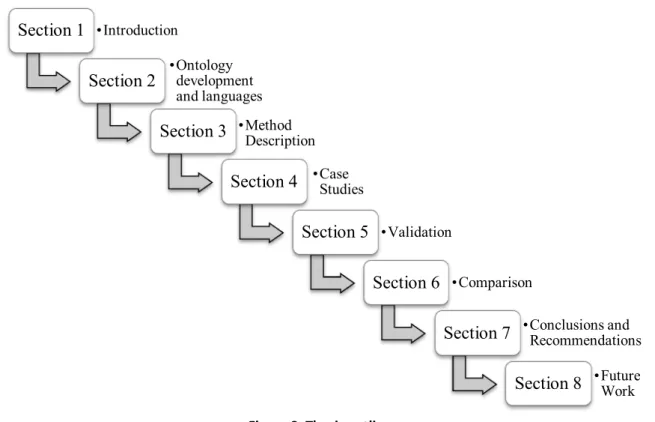
The outline of this thesis is visualized in Fig. 2 and it is organized in the following way. Section 2 presents background information about ontologies, ontology engineering and languages. After that, Section 3 describes the method – MAPDESO, which represents the essence of this work. In Section 4 are presented two industrial case studies with details about how they were conducted and what results were achieved. Then, Section 5 provides the validation of the method. The comparison of the ontology classification with the classification done by an existing software tool is discussed in Section 6. Finally, Section 7 contains the conclusions and the recommendations while Section 8 presents the future work.
Figure 2. Thesis outline. Section 1 • Introduction Section 2 • Ontology development and languages Section 3 • Method Description
Section 4 • Case Studies
Section 5 • Validation
Section 6 • Comparison
Section 7 • Conclusions and Recommendations
- 11 -
2.
ONTOLOGY DEVELOPMENT AND LANGUAGES
Software Engineering (SE), as defined in [1], is the application of a systematic, disciplined, quantifiable approach to the development, operation and maintenance of software. Technology innovation demands from SE reliable and sustainable software products. To answer these demands, SE is aided by other computer science disciplines. Artificial Intelligence (AI), for example, is one of these disciplines that will bring SE to further heights. Particularly ontologies, an AI concept, will help SE by providing tools (in the forms of ontology languages) and methods that can be used together to facilitate the development of understandable, durable and high-quality software [16].
2.1. Definition
The most common definition of ontologies says that an ontology is an explicit specification of a conceptualization [10]. In other words, ontologies are explicit formal specifications of the terms in the domain and the relations among them [10].
According to a more elaborate version of the definition, an ontology defines a common vocabulary for researchers who need to share information in a domain and it includes machine-interpretable definitions of basic concepts in the domain and relations among them [11]. Many disciplines develop standardized ontologies that domain experts use to share and annotate information in their fields. A particular example for such a discipline is medicine, which has produced large, standardized, structured vocabularies. One of them is the SNOMED ontology, which provides a common vocabulary for clinical terms [11]. Figure 3 visualizes part of the SNOMED ontology. It shows some of the medical conditions caused by epilepsy and their relations to different clinical findings.
- 12 - In addition, according to [12], an ontology consists of definitions of concepts, relations and rules and is used in knowledge-based systems with the potential to employ inference. Ontologies are also formalized knowledge, represented in a language that supports reasoning. Once we have defined the term ontology we are ready to dive into the details of ontology development, editors, languages and reasoners.
2.2. Ontology development and editors
Before explaining how to develop ontologies we should answer the question why would someone want to develop an ontology. According to [11], some of the reasons are
to share common understanding of the structure of information among people or software agents;
to enable reuse of domain knowledge;
to make domain assumptions explicit;
to separate domain knowledge from the operational knowledge;
to analyze domain knowledge.
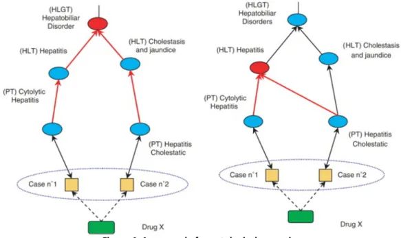
These reasons are complemented by developing an ontology to codify knowledge and to use reasoning to infer new associations from existing ones. An example for this is shown in Fig. 4. On the left is visualized the original hierarchy of the Medical Dictionary for Regulatory Activities (MedDRA). On the right is presented the same hierarchy after ontological reasoning is applied. It is visible that a new association is added between two of the terms – (PT) Hepatitis Cholestatic and (HLT) Hepatitis, because of their definitions and the existing associations.
Figure 4. An example for ontological reasoning.
It is often the case that an ontology is not the goal in itself. Developing an ontology is similar to defining a set of data and their structure to be used by other programs. For instance, problem-solving methods, domain-independent applications, and software agents use ontologies and knowledge bases built from ontologies as data [11].
- 13 - It is important to point out that there is no single correct ontology-design methodology [11]. However, a good understanding of ontologies is needed to understand this work. Therefore, below we mention an ontology-design methodology as an example.
An easy and straightforward way to describe the development of an ontology is the top-down approach, as explained in [12]. The goal of this approach is the level of abstraction. There are four levels of abstraction: meta-meta level, meta level, class level and instance level (ordered in top-down fashion). We begin at the meta-meta level and end at the instance level. Of course, every level influences each level of lower abstraction. Therefore, the results from the meta-meta level are used at the meta level and also at the class and instance levels.
The Meta-meta level is the phase in which the foundation of the ontology is defined. This includes the decision about the used representation language and a definition of its modeling primitives.
The Meta level is the phase in which the key concepts and their relations are defined. This should be done in such a way that the addition of data to an existing ontology should be possible without loss of pre-existing data in that ontology. In other words, the data in an ontology must be preserved.
The Class level is used to add more specific descriptions of the knowledge. Having the key concepts already defined in the previous phase, in this phase we define specific sub-concepts of the key concepts.
The Instance level is the most specific phase out of the four. The instances represent knowledge that is specific to real projects or systems to which the developed ontology will be applied.
Developing an ontology requires an environment where the above-explained process will be executed. Such environments are called ontology editors. Currently, there are many ontology editors, each having its own strengths and weaknesses. According to the World Wide Web Consortium (W3C)1, examples of ontology editors are Protégé2, SWOOP3, OntoStudio4 (previously called OntoEdit), NeOn Toolkit5, Knoodl6, etc.
Out of the existing ontology editors, Protégé has proven to be the most popular and user-friendly (it is supported by a large community of active users) and the one with many available plug-ins [17], [18]. The results from a survey on Semantic Web practices show that Protégé is the most frequently used ontology editor with a market share of 68.2% [17]. Protégé is ahead of all other editors since the second most frequently used editor is SWOOP with 13.6%, after that is OntoEdit with 12.2% and each of the rest (simple text editor, OntoStudio, etc.) has a share of 10% or less [17].
1 http://www.w3.org/ 2 http://protege.stanford.edu/ 3 http://www.mindswap.org/2004/SWOOP/ 4 http://www.ontoprise.de/en/products/ontostudio/ 5 http://neon-toolkit.org/ 6 http://www.knoodl.com/
- 14 - In addition to being the most frequently used editor, Protégé is a free, open source ontology editor and knowledge-based framework. It is based on Java, it is extensible and provides a plug-and-play environment. It contains tools to construct domain models and knowledge-based applications with ontologies. Protégé implements a rich set of knowledge-modeling structures and actions that support the creation, visualization and manipulation of ontologies in various representation formats [18]. The Protégé platform supports two main ways of modeling ontologies via the Protégé-Frames7 and Protégé-OWL8 editors.
2.3. Web Ontology Language
The most recent development in standard ontology languages is the Web Ontology Language (OWL)9. It is endorsed by W3C to promote the Semantic Web10 vision. OWL is a W3C Recommendation for representing ontologies on the Semantic Web. Moreover, OWL is the language with the strongest impact in the Semantic Web with more than 75% of ontologists selecting this language to develop their ontologies [17].
The Web Ontology Language is intended to provide a language that can be used to describe classes (concepts) and the relations between them that are inherent in Web documents and applications. OWL is based on a logical model, which makes it possible for concepts to be defined and described. Complex concepts can be built up out of simpler concepts. Moreover, the logical model allows the use of a reasoner, which can help to maintain the hierarchy of the concepts correctly [13].
An ontology that conforms to OWL, called an OWL ontology, consists of classes, properties and individuals, their descriptions and relations. If an OWL ontology is given, the OWL formal semantics specifies how to derive its logical consequences, i.e. facts that are not literally present in the ontology but entailed by the semantics. This can be achieved by using ontology reasoners.
As explained in the OWL Guide11 and in [13], OWL provides three sublanguages – OWL-Lite, OWL-DL and OWL-Full, designed for use by specific communities of implementers and users. The defining feature of each sublanguage is its expressiveness. OWL-Lite is the least expressive while OWL-Full is the most expressive. OWL-DL’s expressiveness falls in-between. Each sublanguage is an extension of its simpler predecessor, both in what can be legally expressed and in what can be validly concluded.
OWL-Lite is the sublanguage with the simplest syntax. Its intended use is in situations where only a simple class hierarchy and simple constraints are required [13]. Because of the simple class hierarchy and constraints, automated reasoning is not used in OWL-Lite ontologies. OWL-DL is more expressive than OWL-Lite. OWL-DL is intended to be used when users want the maximum expressiveness without losing computational completeness (all 7 http://protege.stanford.edu/overview/protege-frames.html 8 http://protege.stanford.edu/overview/protege-owl.html 9 http://www.w3.org/2004/OWL/ 10 http://www.w3.org/2001/sw/ 11 http://www.w3.org/TR/owl-guide/
- 15 - entailments are guaranteed to be computed) and decidability (all computations/algorithms will finish in finite time) of reasoning systems. OWL-DL is so named because it is based on Description Logics (DL). According to [13], Description Logics represent a decidable fragment of First Order Logic and are amenable to automated reasoning. Therefore, it is possible to automatically compute the classification hierarchy and check for inconsistencies in an ontology that conforms to OWL-DL [13].
OWL-Full is the most expressive sublanguage. It is meant for users who want maximum expressiveness with no guarantees for decidability or computational completeness. Hence, it is not possible to perform automated reasoning on OWL-Full ontologies, as stated in [13].
2.4. Reasoners
A reasoner (also called inference engine) is a software application that derives new facts or associations from existing information [17]. It is a key component for working with ontologies. The survey results in [17] indicate that the most popular reasoners are Jena12, RacerPro13, Pellet14 and FaCT++15.
Jena is a Java framework for building Semantic Web applications, as explained on the Jena project’s home page. Although it includes an inference engine to perform reasoning, it is a comprehensive toolset. It provides a collection of tools and Java libraries to help programmers develop Semantic Web and linked-data applications, tools and servers.
RacerPro is the commercial name of the RACER software (Renamed ABox and Concept Expression Reasoner). The origins of RacerPro are within the area of Description Logics. It can be used as a system for managing OWL ontologies and it can also be used as a reasoning engine for ontology editors such as Protégé.
Pellet is an open-source Java-based OWL-DL reasoner, which provides standard and cutting-edge reasoning services for OWL ontologies. It supports the full expressivity of OWL-DL and is the first sound (all provable statements are true) and complete (all true statements are provable) DL reasoner that can handle this expressivity. It provides functionalities to check consistency of ontologies, classify the taxonomy (this is the superclass-subclass hierarchy in an ontology), check entailments, etc. Pellet is used in a number of projects, from pure research to industrial settings. According to [14], it has proven to be a very reliable tool for working with OWL-DL ontologies and experimenting with OWL extensions.
FaCT++ is the new generation of the FaCT16 OWL-DL reasoner. FaCT++ uses the established FaCT algorithms, but with a different internal architecture. Moreover, FaCT++ is implemented using C++ in order to create a more efficient software tool and to maximize portability. 12 http://jena.apache.org/about_jena/about.html 13 http://www.racer-systems.com/products/racerpro/ 14
Old link: http://www.mindswap.org/2003/pellet/. New link: http://pellet.owldl.com.
15
http://owl.man.ac.uk/factplusplus/
16
- 16 - 2.5. Ontology editor, language and reasoner used in the research
When considering how to use ontologies and ontology reasoning for achieving the goal of this research, we realized that it is imperative to be able to perform automated reasoning on the developed ontology (as already mentioned). This process includes checking the consistency of the ontology and classifying the taxonomy, which in our case means classifying the defects into predefined severity levels according to developed rules. Hence, we made the following choices.
The Protégé platform was selected for the ontology development because of its functionality and popularity, as explained in Section 2.2. Since the ontology language selected was OWL (see Section 2.3) – leading to the development of an OWL ontology, the Protégé-OWL editor was the obvious choice from the Protégé platform.
As explained earlier, the OWL language provides three sublanguages. So, the next question was which sublanguage fits the purposes of our research. It turned out that there are some simple rules of thumb how to find out which sublanguage to use [13]. OWL-Lite was not considered because it provides simple constructs and they are not sufficient. Therefore, the choice had to be made between OWL-DL and OWL-Full. For our research, it is important to be able to carry out automated reasoning on the ontology and, as explained in Section 2.3, DL provides such a possibility while Full does not guarantee it. Hence, OWL-DL was chosen as the OWL sublanguage.
Last but not least, we had to choose an appropriate reasoner to use in the ontology. At this point of time, we already knew that the ontology will be developed using Protégé and it will conform to OWL-DL, so the choice of the reasoner was relatively straightforward. As explained in Section 2.4, Pellet supports the full expressivity of OWL-DL and using it we can check the consistency of the ontology and classify the taxonomy. Therefore, we decided to use Pellet as the OWL-DL reasoner in the research.
2.6. Section summary
In this section we provided information about ontologies, ontology development and editors, the Web Ontology Language and popular reasoners. Moreover, we discussed which ontology editor, language and reasoner we used in the research and why. Hence, it is now safe to continue further with the details of the developed method and the case studies in the research.
- 17 -
3.
METHOD DESCRIPTION
The end result from the method described in this section – MAPDESO, is the solution to the problems we are facing, as mentioned in Section 1.1 and shown in Fig. 1.
The method has culminated in the development of an ontology for automated prediction of defect severity (automatic classification of defects into the severity levels from the IEEE standard in [2]). We should point out that the two main purposes to use this ontology, though not the only ones, are
sharing common understanding of the structure of information among people or software agents – achieved by using the IEEE standard for the defects’ attributes and their values;
enabling reuse of domain knowledge – achieved by reusing the ontology and the developed classification rules in order to predict the severity levels of defects from various projects.
Although there are different reasons for developing and using ontologies, as mentioned in Section 2.2, it turns out that the above two are the most common reasons for using ontologies, as evident by the survey results in [17].
The process of developing the ontology is an essential part of MAPDESO. However, once the ontology is developed, this process does not need to be repeated when using the method. In other words, developing the ontology is done only once, while using it can be done multiple times. In the first subsection we will describe the process of developing the ontology so that it will be clear later how the ontology and the classification work. After that, we will explain the method and we will refer to using the ontology as a black box process – only the input and the output will be mentioned.
3.1. Developing the ontology
In Section 2.2, we referred to an approach for ontology development. For clarity and understandability, we will follow that approach when explaining how the ontology was developed.
3.1.1. Meta-meta level
This is the phase for defining the foundation of the ontology. In fact, we have completed this phase since we already know which ontology editor, language and reasoner we will use – Protégé-OWL, OWL-DL and Pellet, respectively (for more information refer to Sections 2.2-2.5). Hence, the ontology development approach has a predefined meta-meta level.
3.1.2. Meta level
This is the phase in which the key concepts in the ontology and their relations are defined. For our ontology, in this phase, we defined and created the base classes and the properties.
- 18 - Classes are the focus of most ontologies and they represent concepts in a domain of discourse [11]. They are described using formal (mathematical) descriptions that state precisely the requirements for membership of the class. They may be organized into a superclass-subclass hierarchy, also known as a taxonomy [13]. At this level of ontology development we created the following classes:
Defect – this class represents all defects.
Effect – this class represents attribute Effect from the IEEE standard in [2]. Its values are quality properties and classes of requirements that are impacted by a failure caused by a defect.
Type – this class represents attribute Type from the IEEE standard. The type of a defect represents the nature of that defect. The attribute’s values are categorizations based on the class of code or the work product within which a defect is found.
InsertionActivity – this class represents attribute Insertion activity from the IEEE standard. Its values are the activities during which a defect is inserted.
DetectionActivity – this class represents attribute Detection activity from the IEEE standard. Its values are the activities during which a defect is detected.
We created the properties describing the relations between the defects and the attributes from the standard. Hence, these properties describe the relations between class Defect and classes
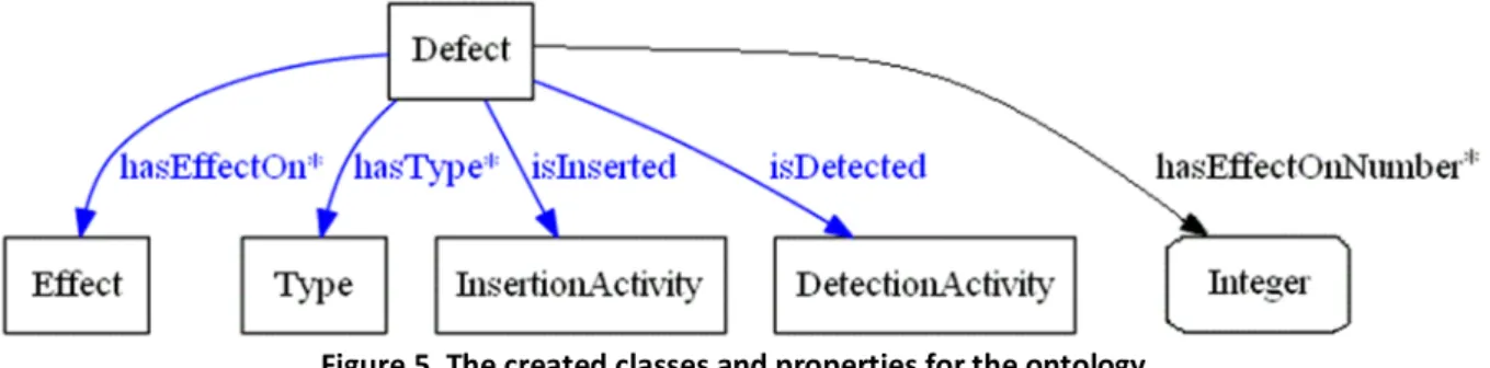
Effect, Type, InsertionActivity and DetectionActivity (if these properties relate to the classes, then the same relations will also hold for the respective subclasses). Figure 5 presents the created classes and properties for the ontology.
Figure 5. The created classes and properties for the ontology. On the figure are shown five properties. They are the following:
hasEffectOn* – this is an object property (linking an individual to an individual [13]) that relates class Defect (domain of the property) to class Effect (its range). Hence, this property relates a defect to one or more quality properties (e.g., performance, functionality) affected by it. The asterisk at the end of the property means that its range accepts one or more values.
hasType* – this is an object property that relates class Defect (domain) to class Type
(range). This property relates a defect to one or more values of the range (e.g., data, interface). The asterisk at the end of the property means that its range accepts one or more values.
isInserted – this is an object property that relates class Defect (domain) to class
- 19 - (e.g., design, coding). The absence of an asterisk at the end of the property means its range accepts only a single value, which implies that this is a functional property [13].
isDetected – this is an object property that relates class Defect (domain) to class
DetectionActivity (range). In other words, this property relates a defect to its detection activity (e.g., supplier testing, production). The absence of an asterisk at the end of the property means its range accepts only a single value, which, as above, implies this is a functional property [13].
hasEffectOnNumber* – this is a datatype property (linking an individual to a specific datatype [13], for example, integers) that relates class Defect and its subclasses (domain) to datatype Integer (range). This property represents the number of values (an integer) of attribute Effect that are affected by a defect. The asterisk at the end of the property means that its range accepts one or more values (the integer 1 or the integer 2, etc.).
It is important to note that the relations defined by the five properties will be used specifically for the subclasses of the classes mentioned above. Moreover, in Fig. 5, the object properties are depicted in blue color while the datatype property is depicted in black for easier differentiation. The datatype Integer is given in a rounded rectangle to point out that it is not a class (depicted with rectangles) but a datatype.
3.1.3. Class level
In this phase we define the sub-concepts of the key concepts defined at the Meta level. In the current ontology, this means that we will add the required subclasses to the existing classes. Hence, for class Defect, we defined six subclasses. They are the following:
DefectID – this class represents all defects input in the ontology as its subclasses.
DefectWithBlockingSL – this class represents all defects assigned blocking severity level (they are displayed as its subclasses after performing the ontology classification).
DefectWithCriticalSL – this class represents all defects assigned critical severity level (they are displayed as its subclasses after performing the ontology classification).
DefectWithMajorSL – this class represents all defects assigned major severity level (they are displayed as its subclasses after performing the ontology classification).
DefectWithMinorSL – this class represents all defects assigned minor severity level (they are displayed as its subclasses after performing the ontology classification).
DefectWithInconseqSL – this class represents all defects assigned inconsequential severity level (displayed as its subclasses after performing the ontology classification). The five classes that are related to the five severity levels from the IEEE standard are defined as disjoint from each other because every defect is assigned one and only one severity level. In the ontology class hierarchy the defects are subclasses of class DefectID. As mentioned earlier and clearly stated in [13], one of the key features of OWL-DL is that the superclass-subclass relationships can be computed automatically by a reasoner. Hence, to use this feature, we have to input the specific defects as separate classes. Moreover, they are input as subclasses of class DefectID for clarity and readability of the overall ontology taxonomy.
- 20 - Figure 6 presents the class hierarchy for class Defect and its subclasses.
Figure 6. Class Defect and its subclasses.
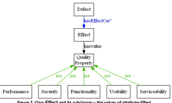
Next, we created the subclasses for the other four classes. Since the classes are the attributes from the IEEE standard, their subclasses are the values of the respective attributes. For clarification and readability, Fig. 7 shows class Effect together with its relation to the quality properties (the hasvalue arrow). Moreover, the figure shows the created subclasses (using
isa arrows) which are the values of attribute Effect. These subclasses are listed below together with their definitions, as taken from the IEEE standard in [2]:
Functionality – actual or potential cause of failure to correctly perform a required function (or implementation of a function that is not required), including any defect affecting data integrity.
Usability – actual or potential cause of failure to meet ease of use requirements.
Security – actual or potential cause of failure to meet security requirements, such as those for authentication, authorization, privacy/confidentiality, accountability (e.g., audit trail or event logging), and so on.
Performance – actual or potential cause of failure to meet performance requirements (e.g., capacity, computational accuracy, response time, throughput, or availability).
Serviceability – actual or potential cause of failure to meet requirements for reliability, maintainability, or supportability (e.g., complex design, undocumented code, ambiguous or incomplete error logging).
- 21 - Figure 8 presents class Type and its subclasses using isa arrows. These subclasses are the values of attribute Type. They are listed and defined below using the definitions from [2]:
Data – defect in data definition, initialization, mapping, access, or use, as found in a model, specification, or implementation.
Interface – defect in specification or implementation of an interface (e.g., between user and machine, between two internal software modules, between software module and database, between internal and external software components, between software and hardware, etc.).
Logic – defect in decision logic, branching, sequencing, or computational algorithm, as found in natural language specifications or in implementation language.
Description – defect in description of software or its use, installation, or operation.
Syntax – nonconformity with the defined rules of a language.
Standards – nonconformity with a defined standard.
Other – defect for which there is no defined type.
Figure 8. Class Type and its subclasses – the values of attribute Type.
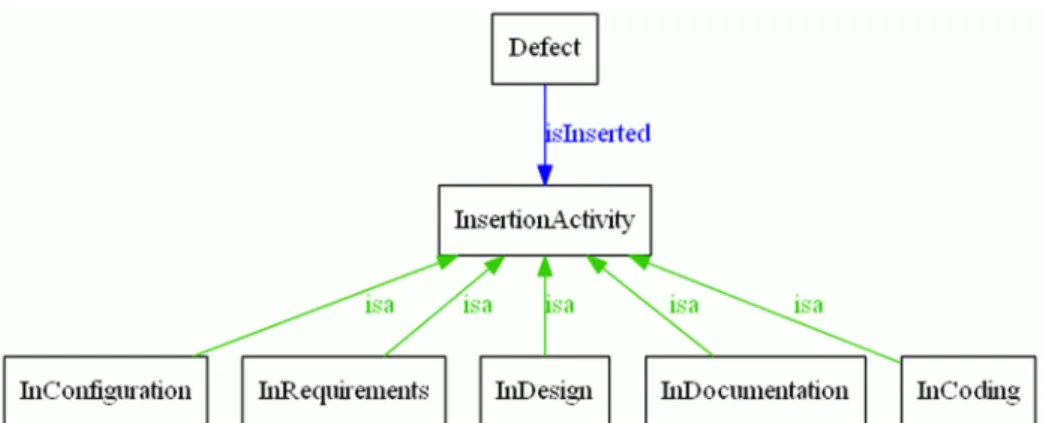
Figure 9 shows class InsertionActivity and its subclasses. The subclasses represent the values of attribute Insertion activity. They are given below together with their definitions from [2]:
InRequirements – defect inserted during requirements definition activities (e.g., elicitation, analysis, or specification).
InDesign – defect inserted during design activities.
InCoding – defect inserted during “coding” or analogous activities.
InConfiguration – defect inserted during product build or packaging.
InDocumentation – defect inserted during documentation of instructions for installation or operation.
Figure 10 presents class DetectionActivity and its subclasses, which represent the values of attribute Detection activity. These subclasses and their definitions from [2] are listed below:
FromRequirements – defect detected during synthesis, inspection, or review of requirements.
FromDesign – defect detected during synthesis, inspection, or review of design.
- 22 - Figure 9. Class InsertionActivity and its subclasses – the values of attribute Insertion activity.
Figure 10. Class DetectionActivity and its subclasses – the values of attribute Detection activity.
FromSupplierTesting – defect detected during any testing conducted by the supplier.
FromCustomerTesting – defect detected during testing conducted by the customer.
FromProduction – defect detected during production operation and use.
FromAudit – defect detected during an audit (pre-release or post-release).
FromOther – defect detected during any other activity, such as user/operator training or product demonstrations.
3.1.4. Instance level
This is the most specific phase. Instances represent knowledge that is specific to real projects or systems to which the developed ontology will be applied. Hence, the specific defects input in the current ontology can be regarded as instances. However, as already explained, the defects are input as classes that are subclasses of DefectID. For example, Fig. 11 shows five particular defects input in the ontology as subclasses of DefectID (the other defects are not present because of space concerns). In fact, Fig. 11 represents an extended version of Fig. 6 up to some minor layout differences, which are explained later.
- 23 -
3.1.5. Classification rules
For the current ontology we have also developed classification rules that are responsible for the classification of the input defects into the five severity levels from the standard. We have developed five sets of rules – one set of rules for each of the five classes
DefectWithBlockingSL, DefectWithCriticalSL, DefectWithMajorSL, DefectWithMinorSL
and DefectWithInconseqSL.
The classification rules represent necessary and sufficient conditions for a defect to belong to one and only one of the above five classes. In other words, if a defect satisfies the set of rules corresponding to one of the five classes, then this defect belongs to that class and is assigned the severity level corresponding to the class (i.e., blocking-, critical-, major-, minor- or inconsequential severity level). On the other hand, if a defect belongs to one of the five classes, then it satisfies the set of rules corresponding to that class.
Next, we list the rules for each of the five classes and explain their meaning.
Rule 1 (R1) defines the necessary and sufficient conditions for a defect with blocking severity level (class DefectWithBlockingSL). It consists of two sub-rules and they are the following: (R1.1) Defect
(R1.2) hasEffectOnNumbermin 4
These sub-rules mean the following: an entity is assigned blocking severity level if and only if it is: (R1.1) a defect; (R1.2) affecting at least four of the values of attribute Effect (which represent quality properties as already mentioned).
Rule 2 (R2) defines the necessary and sufficient conditions for a defect with critical severity level (class DefectWithCriticalSL). It consists of five sub-rules and they are the following: (R2.1) Defect
(R2.2) (hasEffectOnNumberexactly 2) or (hasEffectOnNumberexactly 3) (R2.3) (isInsertedonly (InDesignorInRequirements)) or
((isInserted only (InCoding or InConfiguration)) and ((hasEffectOnNumber exactly 3) or (hasTypemin 2)))
(R2.4) hasTypeonly (DataorInterfaceorLogic)
(R2.5) isDetectedonly (FromCodingorFromSupplierTestingorFromCustomerTesting orFromProduction)
These sub-rules mean the following: an entity is assigned critical severity level if and only if it is: (R2.1) a defect; (R2.2) affecting exactly two or exactly three of the values of attribute Effect; (R2.3) inserted during the design phase or the requirements phase, or inserted during the coding phase or the configuration phase and affecting exactly three values of attribute Effect or at least two values of attribute Type; (R2.4) affecting one or more of the values
- 24 - Data, Interface or Logic of attribute Type; (R2.5) detected during the coding phase, or the supplier testing phase, or the customer testing phase, or during production use.
In Rule 2 the operator or represents logical disjunction and the operator and represents logical conjunction. The same applies for these operators in the other rules (if they are present in the other rules).
Rule 3 (R3) defines the necessary and sufficient conditions for a defect with major severity level (class DefectWithMajorSL). It consists of two sub-rules and they are the following: (R3.1) Defect
(R3.2) notDefectWithBlockingSLand
(not DefectWithCriticalSLor ((isInsertedonly (InCoding orInConfiguration)) and
(hasEffectOnNumber exactly 2) and ((hasType only Data) or (hasType only
Interface) or (hasTypeonlyLogic)))) and
notDefectWithMinorSLand
notDefectWithInconseqSL
These sub-rules mean the following: an entity is assigned major severity level if and only if it is: (R3.1) a defect; (R3.2) not a defect with blocking severity level, and not a defect with critical severity level or it is inserted during the coding phase or the configuration phase and is affecting exactly two values of attribute Effect and only one of the values Data or Interface or Logic of attribute Type, and not a defect with minor severity level and not a defect with inconsequential severity level (the reason for adding the part of this sub-rule after not DefectWithCriticalSL and before and not DefectWithMinorSL is explained in details in Appendix A in order not to disrupt the flow of the method description).
In Rule 3 the operator not represents negation (also called logical complement). The same applies for this operator in the other rules (if it is present in the other rules).
Rule 4 (R4) defines the necessary and sufficient conditions for a defect with minor severity level (class DefectWithMinorSL). It consists of four sub-rules and they are the following: (R4.1) Defect
(R4.2) hasEffectOnsome (notUsabilityandnotSecurity) (R4.3) hasEffectOnonly (notUsabilityandnotSecurity) (R4.4) hasEffectOnNumbermax 1
These sub-rules mean the following: an entity is assigned minor severity level if and only if it is: (R4.1) a defect; (R4.2) affecting some values of attribute Effect that are not Usability and Security; (R4.3) affecting only values of attribute Effect that are not Usability and Security (this sub-rule is needed in order to make sure that the defect can only have the specified values – such a sub-rule is known as a closure axiom [13]); (R4.4) affecting at most one value (and, therefore, exactly one) of attribute Effect.
- 25 - Rule 5 (R5) defines the necessary and sufficient conditions for a defect with inconsequential severity level (class DefectWithInconseqSL). It consists of three sub-rules and they are: (R5.1) Defect
(R5.2) hasEffectOnsomeUsability
(R5.3) hasEffectOnonlyUsability
These sub-rules mean the following: an entity is assigned inconsequential severity level if and only if it is: (R5.1) a defect; (R5.2) affecting value Usability of attribute Effect; (R5.3) affecting only value Usability of attribute Effect (as above, this sub-rule is needed in order to make sure that the defect can only have the specified value).
The classification rules complement the developed ontology. Hence, it is important to point out that these rules
were developed manually based on the pattern of the empirical data (from Case Studies 1 and 2 – see Section 4) and on heuristic strategies, such as intuitive judgment, etc. The rules were later improved to be as general as possible in order to apply the method to various software projects (see the validation in Section 5 for an example).
use designers’ recommendations – the designers’ logical argumentation for translating the user requirements into the software design and for assigning severity levels to eventual defects is studied and incorporated in the rules.
give more weight to defects inserted during the requirements and design phases than during the coding and configuration phases – this way, the defects inserted earlier in the software cycle will be given higher severity levels and hence, fixed sooner than other defects. Therefore, more users of the software product will be satisfied.
consider the quality properties affected by a defect as a key component (but are not restricted only to that) for classifying the defect into one of the five severity levels. Thus, the greater the extent to which a defect affects the quality of the software, the higher the severity level that will be assigned to the defect.
As a result, using these rules, defects will be assigned severity levels in a way that will reflect what is important not only according to the developers/test analysts but also according to the users of the software system.
3.2. The method flow
It is clear now how the ontology was developed. In this subsection we will focus on how to use the ontology in order to automatically predict the severity levels of defects from different projects. The method consists of the following steps: detecting defects; analyzing and converting the information about the defects into the information needed as input for the ontology; entering the converted information about the defects into the ontology; and, lastly, predicting the severity levels of the defects input in the ontology through a single click of a button. These steps are illustrated in the UML activity diagram in Fig. 12 on the next page. The diagram represents a reference point for the description of the whole method flow.
- 26 - Figure 12. Activity diagram for automated prediction of defects’ severity levels.
- 27 - Before explaining the details of MAPDESO, it should be noted that there are two options when using it, as illustrated in Fig. 12. The first option is to apply the method to a project that does not use the IEEE standard in [2] for describing its defects. And the second option is to apply the method to a project that has adopted the IEEE standard for describing its defects. The obvious difference is the omission of the second step from the method as given above. The reason stems from the fact that once a project is using the IEEE standard for describing its defects, then the defects and their information can be directly input in the ontology. There is no need to convert the defects’ information because it is already in the form needed to input the defects in the ontology. However, below we will describe and explain all steps of the method.
3.2.1. Detection of defects
The testing activity in the software development cycle detects defects, which software teams have to fix. For our research, testing at the system level was the main source of defects. However, we also took into consideration defects detected during the coding phase and during maintenance. Therefore, the four activities, used in this method to detect defects (no detected defects is also a possibility), as defined in [2], are
coding – defects detected during synthesis, inspection, or review of source code;
supplier testing – defects detected during testing conducted by the supplier;
customer testing – defects detected during testing conducted by the customer;
production – defects detected during production operation and use.
As explained earlier, the next step (Section 3.2.2) is required for projects not using the IEEE standard for describing their defects and it is redundant for projects using the standard for describing their defects.
3.2.2. Analysis and conversion of the defects’ information
Taking this step implies that the software project to which the method is applied has not adopted the IEEE standard for describing its defects. Hence, the information about detected defects is gathered and stored in a way that is, most probably, specific only for the project in question. For example, the set of severity levels might contain three, four, five or more levels; the defect tracking system might not contain any information about a defect’s insertion activity or type; etc. After analyzing the available information about defects from such a project, it is evident that this information has to be converted into the defect attributes and their values from the standard in [2] in order to apply the method to the project. In our research, the analysis and conversion were done manually. This manual process consisted of:
studying the project documentation and the available information from the defect tracking system – this way, we were able to understand the information contained in the defect reports;
conducting interviews with members of the software team – we used their project knowledge in order to gather the information needed for the conversion.
After that, we analyzed the data acquired from the above two steps and if the data were not enough, the steps were repeated. Then, based on the analysis and on the recommendations of
- 28 - the software team members, we converted the gathered information about the defects into the defect attributes and their values from the standard. The used attributes are Effect, Type, Insertion activity and Detection activity, as defined in [2].
It turned out that it is quite easy to present the results from the analysis and conversion step in a table. The table has five columns representing the Defect ID and the used attributes and every row after the first one (which is the top row) represents separate defects with the respective values of the attributes for each and every defect. Table 1 below shows the top row of the table together with example values of the attributes for a fictitious defect.
Table 1. The format of the table presenting the results from the analysis and conversion step
Defect ID Effect Type Insertion
Activity
Detection Activity 001 Functionality;
usability Logic Coding
Supplier testing
… … … … …
As a future direction, there might be another way to complete the analysis that, in fact, can automate it. It is possible to use natural language processing and data mining algorithms to extract the needed information from the defect reports. This way, the extracted defect information will be converted into the attributes and their values from the standard. Although this option was not used in the research, it might be a very useful way to further automate this method, as explained in Section 8.
3.2.3. Entering the converted information into the ontology
This step presents a few ways for entering the converted information into the ontology using the Protégé-OWL editor.
When Table 1 is completed the method continues with entering the converted information (or, in other words, the information from Table 1) into the ontology. This step can be divided in two. First, the classes for all defects that will be input in the ontology should be created as subclasses of class DefectID (as explained in Section 3.1.3). And second, the converted information about the defects (from Table 1) should be added to the created classes.
The editor we used for developing the ontology – Protégé-OWL, gives us three options for inputting the defects in the ontology. The first one is to manually create the classes for all defects and fill out all properties and the values of their respective ranges for every class. The second option is to use two editors – with the first one (called Create Multiple Subclasses) the classes are created, while with the second one (called Quick Restriction Editor) the information about the defects is added to the classes. The third option is to use the Excel Import plug-in – a batch importing plug-in from Protégé-OWL. It provides the opportunity to generate classes from the contents of Excel or CSV (comma-separated values) files. For example, the classes for the defects can be generated from the contents of the first column of Table 1. Then, to add the converted information to the created classes, restrictions are
- 29 - generated or, in other words, the first column of Table 1 is related to the other columns via the properties defined in Section 3.1.2.
If Table 1 contains ten or twelve defects, for instance, then it will be relatively easy to enter them and their information manually into the ontology. If, however, the table contains many defects – twenty or more, then it is also possible to enter everything manually but it will be very time-consuming. Hence, in either case, it is more feasible not to use the first option. Completing the current step using the other two options is similar to a great extent. Since the second option provides important details for inputting the defects in the ontology, we used this option. The two editors are explained below together with some examples.
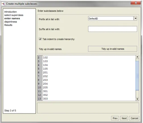
3.2.3.1. Creating the classes for the defects – editor Create Multiple Subclasses
Editor Create Multiple Subclasses is depicted in Fig. 13. The left side of the figure shows the steps that need to be completed in order to create the classes for all defects. This editor gives the opportunity to select the superclass that will contain all created classes (step 2 “Select superclass”). In this case, the superclass is class DefectID. Then, the names of the classes can be entered (or copied from other sources) and they will be created as subclasses of the selected superclass (step 3 “Enter names” – this step is shown in details in Fig. 13). It is valuable to know that prefixes and suffixes can be added for all class names and that the editor automatically validates that the entered terms are valid Protégé names. Moreover, the editor allows disjoints (step 4 “Disjointness”) to be added automatically between all new siblings (and also between the new and the existing ones). We need to add disjoints since all defects are entered as separate and unique classes. In the end, the successful creation of the classes for all defects is confirmed by the editor (step 5 “Results”).