Engineering Structures 229 (2021) 111596
Available online 16 December 2020
0141-0296/© 2020 Elsevier Ltd. All rights reserved.
Characterization of the out-of-plane behavior of CLT panel connections
Rafael A. Salgado
*, Serhan Guner
Department of Civil and Environmental Engineering, University of Toledo, Toledo, OH 43607, USA
A R T I C L E I N F O Keywords: Connections Cross-laminated timber Failure analysis Finite element Nonlinear modeling Numerical analysis Out-of-plane Simulation Structural mechanics Tsunami A B S T R A C T
The increasing damage caused by natural hazards has stimulated the research for new construction systems that can perform well during these events. Cross Laminated Timber (CLT) is a relatively new and robust construction material that has been extensively investigated under seismic load conditions, during which it exhibited good performance. However, its potential as a resilient alternative for natural hazard events that primarily engage the out-of-plane response of the building (e.g., hurricanes, flooding, storm surge, and tsunamis) has not yet been explored. A critical step to assess the performance of platform type CLT buildings to these events is to understand and characterize their out-of-plane behavior as they are critical in the effective load transfer to the in-plane resisting elements. However, there is a major lack of knowledge on the behavior of CLT panel connections subjected to out-of-plane load conditions. This creates a significant barrier in the adoption of CLT structures for resilient wood buildings and communities. The objective of this study is to advance the current understanding and characterize the behavior of CLT panel connections under out-of-plane-induced load conditions. A secondary objective is to identify key connection design parameters and quantify their influences on the out-of-plane behavior. To achieve these objectives, high-fidelity nonlinear numerical models of CLT panel connections are developed, experimentally validated, and investigated under two tsunami-induced out-of-plane load conditions. A numerical investigation with 48 numerical models is performed and the analysis of variance (ANOVA) method is used to quantify the influences of three key connection design parameters on the out-of-plane behavior of CLT panel connections. The results indicated that the crushing of the wall panel’s wood fibers dictated the behavior in one of the out-of-plane directions considered while the axial withdrawal of the nails on the wall side of the connections dictated the behavior in the other direction. A simplified equation and a mechanics-based procedure were developed for estimating the load capacity and quantifying the nail contribution to the capacity of the connections under the out-of-plane load conditions considered.
1. Introduction
Every year, sixteen major earthquakes are expected to occur around the world [1]. Although no data indicates that this number has been rising in recent years, the damage caused by these events has been rapidly increasing due to the urbanization of vulnerable areas. As a result, the ten most costly earthquakes of all time have occurred in the past 30 years – three of them in the past decade – and have inflicted more
than $260bn in damage [2]. This increasing damage has fostered research for new infrastructure systems to create communities with improved resilience. Cross Laminated Timber (CLT) is a relatively new and robust construction material comprised of strong panels formed from wooden boards placed crosswise. The seismic performance of CLT buildings has been extensively investigated over the past decades, where it has been shown to perform very well subjected to earthquake
excitations [3–14].
Earthquakes are the most common source of tsunamis. Major tsu-namis occur about once per decade [15] and, similar to earthquakes, the damage caused by these events has been greatly amplified by vulnerable coastal areas becoming more densely populated. The 2004 Indian Ocean and 2011 Japan events, for example, resulted in approximately 250,000 fatalities, dislocation of more than 350,000 people, and astronomical costs of more than $350 bn. [16–18]. These two events alone have surpassed the aggregated damage cost of the ten most costly earthquakes of all time. Consequently, to increase the resilience of coastal commu-nities, new infrastructure systems must perform well during both seismic and subsequent tsunami events. Although CLT buildings have shown good performance under seismic events, the potential of this new ma-terial as a tsunami-resilient structural system has not yet been explored.
A tsunami wave impact is similar to a wind load in the sense that it * Corresponding author.
E-mail addresses: [email protected] (R.A. Salgado), [email protected] (S. Guner). Contents lists available at ScienceDirect
Engineering Structures
journal homepage: www.elsevier.com/locate/engstruct
https://doi.org/10.1016/j.engstruct.2020.111596
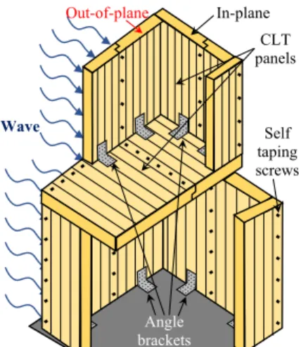
first engages the out-of-plane CLT panels which, subsequently, transfer the applied load to the stiffer in-plane panels, as shown in Fig. 1. During wind load design, most of the wind forces are considered to be trans-ferred to and resisted by the in-plane elements. Tsunami loads, on the other hand, are several times larger than wind loads. For instance, wall pressures created by wind speeds of 322 km/h (i.e., 70 km/h above the category 5 hurricane speed limit) are ten times lower than wall pressures created by a 2.5 m high tsunami wave, according to the wind wall pressure tables [19] and the tsunami force analysis methods provided in [19–21]. If the out-of-plane walls fail to resist the tsunami load, no load transfer will occur to the in-plane panels and the tsunami wave will abruptly inundate the building, applying forces for which the panels may not be designed for, causing extensive damage, and possibly collapse. Consequently, it becomes clear that, under tsunami load con-ditions, the effective load transfer from the out-of-plane to the in-plane resisting elements relies significantly on the capacity of the out-of-plane CLT panels to resist the imposed loads. For this reason, this study dis-cusses the out-of-plane behavior of CLT panel connections in the context of tsunami events, which is a relatively unexplored research area; however, the results can also be applied to other natural hazard events that primarily engage the out-of-plane response of the building such as hurricanes, flooding, and storm surges.
A few available studies have examined the out-of-plane behavior of isolated CLT panels [22–25] while neglecting the behavior of the panel connections. CLT panel connections are used to join the CLT wall panels to another CLT floor panel or the foundation, as shown in Fig. 1 for a platform type of CLT building (i.e., floor slabs are supported by the wall panels below). These wall-to-floor and wall-to-foundation panel con-nections are commonly comprised of metal connectors (such as angle brackets and hold-downs), steel fasteners (such as nails, screws, or bolts), and the local section of the connected CLT panels or the foun-dation. CLT panel connections are known to dictate the performance of CLT structures, supplying most of the flexibility and providing the necessary strength, stiffness, and ductility [3,26–31]. Their behavior is usually governed by certain key connection design parameters, such as the number of fasteners on the wall and floor sides of the connection, and the wood species used in the CLT panel. Consequently, CLT panel connections are expected to dictate the out-of-plane performance of platform type CLT buildings.
To this date, there are no studies in the literature that have attempted to experimentally characterize the out-of-plane behavior of CLT panel connections. Very few studies have explicitly accounted for such behavior in finite element models of CLT structures. However, in these studies, the out-of-plane response is usually modeled using simplified numerical modeling techniques (e.g., [32]), assumed to be equal to the in-plane response (e.g., [33]), or to have a constant elastic response (e. g., [34]). Furthermore, it is also not known what key connection design
parameters are significant and how they influence the global out-of- plane response of the connections. This knowledge gap creates a sig-nificant barrier for the adoption of the CLT material for the creation of tsunami-resilient buildings and communities. Based on the existing literature and the reasons discussed above, the characterization of the out-of-plane response of CLT panel connections is a valuable advance-ment towards more reliable out-of-plane load analyses (such as for wind loads) and towards the performance assessment of platform type CLT buildings.
The main objective of this study is to advance the current under-standing and characterize the behavior of wall-to-floor and wall-to- foundation CLT panel connections under out-of-plane load conditions. The secondary objective is to identify the key connection design pa-rameters and quantify their influences on the out-of-plane behavior, including the load and displacement capacities.
2. Methodology
To achieve the research objectives, experimentally validated high- fidelity nonlinear numerical models of wall-to-floor and wall-to- foundation panel connections were developed and subjected to two out- of-plane load conditions. For brevity, panel connections will simply be referred from now on as connections. The angle brackets, fasteners, and CLT panel layup (i.e., number of layers used and their thickness) selected for use in this study are shown in Fig. 2. This selection was made due to their common use in today’s platform type CLT buildings and their
available in-plane behavior characterization [6,34–42], the results of which were used in this study for experimental validation purposes. The validated models were used to advance the current understanding and characterize the out-of-plane behavior of the connections. A numerical investigation with 48 models was performed and the results were assessed using the analysis of variance (ANOVA) method [43] to statistically identify and quantify the influence of each parameter on the out-of-plane behavior of the connections. Using the results, a simplified equation and a mechanics-based procedure were developed for estimating the load ca-pacity and quantifying the nail contribution to the caca-pacity of the con-nections under the out-of-plane load conditions considered.
3. High-fidelity nonlinear numerical modeling
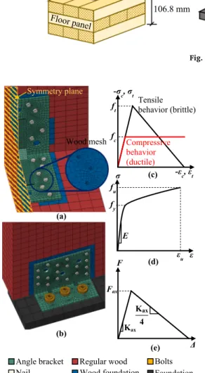
The objective of the high-fidelity numerical model is to enable an accurate simulation of the nonlinear response including the contact, plasticity, and large deformations of the components of the connection shown in Fig. 2. 8-node 24 degrees-of-freedom 3D continuum brick el-ements were used in combination with suitable nonlinear material models (to be discussed below) in the Abaqus program [44]. To ensure an accurate simulation, the employed modeling approach deviated from commonly adopted simplified techniques to model CLT structures, such as the use of zero-length link elements to model the connections (e.g., [37]), springs to simulate the fastening components (e.g., [45]), and layered shell elements to simulate the CLT panels (e.g., [34]).
The wood panels were modeled using two distinct formulations. The first formulation employs an orthotropic uniaxial stress–strain wood
response idealized as a linear-elastic region followed by a post-elastic brittle (i.e., for tension failure modes) or ductile behavior (i.e., for compressive failure modes) as shown in Fig. 3c. This formulation was used to model the wood regions at 4.5d (i.e., nail diameter) or greater distances from the nails, termed herein regular wood region (see Fig. 3a
and Fig. 3c). The second formulation employs the Hong and Barret [46]
wood foundation approach (see Fig. 3a and Fig. 3b). This formulation was used to model the wood regions in the vicinity of the nails (i.e., closer than 4.5d from the nails) as it accounts for the softening of the wood’s mechanical properties due to the damage caused by the
instal-lation of the nails [47].
An isotropic hardening plastic material model was employed to simulate the nonlinear behavior of the fasteners and angle brackets, Angle brackets In-plane CLT panels Wave Self taping screws Out-of-plane
which are typically manufactured from stainless-steel or high-carbon alloy steel. The response of these elements was numerically idealized with a bilinear stress–strain model as shown in Fig. 3d. The European
Yield Model [48] of dowel-type fastening components embedded in wood – adopted by Eurocode 5 [49] and the National Design
Specifi-cation for Wood Construction [50] – classifies the yield of fasteners in
four different modes. The occurrence of each yield mode depends on the wood and fastener material and their geometrical properties. As such, the combined wood and steel modeling approaches employed numeri-cally can account for these bending failure modes. The axial withdrawal behavior of the nails embedded in the wood was modeled following a bilinear axial force–displacement curve dictated by the initial axial
withdrawal stiffness (Kax) and the axial withdrawal capacity (Fax) as shown in Fig. 3e. The models of Eurocode 5 [49], shown in Eq. (1), and Uibel and Blaß [51], in Eq. (2), have been shown to provide a good
estimate of Kax and Fax [28,52]. The nails are typically fastened using pneumatic tools that use compressed air to drive nails into the wood, which causes a prestress state on the nails under service load conditions. Consequently, in the numerical models, an axial compressive pressure load was applied on the nail heads based on typical nail gun air
pressures. Kax= 4 90ρ 1.5d0.8 (1) Fax=0.35d0.8l0.9efρ 0.75 (2)
where ρ is the density of the wood (kg/m3); d is the diameter of the fastening component’s shank (mm); and lef is the threaded length of the
fastening component (mm).
The developed numerical models of the wall-to-floor and wall-to- foundation connections are shown in Fig. 3a and Fig. 3b, respectively. A surface-to-surface discretization method was used to define the me-chanical interface interaction between the different elements of the model (i.e., the CLT panels, fasteners, and angle brackets). This dis-cretization utilized the concept of master and slave contact pairs in which contact interaction behaviors were defined to enforce the contact constraints. The behavior of each contacted interface was characterized in both the normal and tangential directions. The normal direction was dictated by a hard contact algorithm (i.e., the nodes of the slave surface elements were constrained not to penetrate the master surface) while the tangential behavior was dictated by a friction contact algorithm with friction coefficients of 0.3, 0.35, and 0.4 for steel-on-steel, wood-on- steel, and wood-on-wood contact [29,46], respectively – except for the
tangential behavior between the fastening component and the CLT panel, which was governed by the axial withdrawal behavior discussed above and shown in Fig. 3e.
The out-of-plane load was applied on the nodes of the sides of the CLT wall panel, as shown in Fig. 2. This loading approach did not allow the capture of prying actions on the connections caused by the out-of- plane rotation of the wall panels. Rather, the load application was idealized to represent the approach that would be likely used in a real testing machine, in which the load cell would be attached to the wall panel using coupling mechanisms. The match between the numerical and a possible experimental loading approach was also preferred to allow an easy validation of the numerical results by future experimental studies. In addition, the non-inclusion of secondary effects such as the prying action follows the current testing practice of CLT connections. For instance, shear tests apply pure shear forces on the specimen (e.g.,
[41,42]) and usually neglect the effects of the overturning uplift forces
that would likely develop on the panel. Under all load conditions considered, monotonically increasing displacement was applied to the CLT wall panel while the floor panel or foundation steel plate had the bottom face completely fixed. The angle bracket of the wall-to-floor connection has a symmetric configuration, which allowed the half- modeling of the entire system as shown in Fig. 3a. The boundary con-ditions applied to the symmetry plane depended on the symmetry of the applied load. Under load conditions that were symmetric in relation to the symmetry plane, fixed translation perpendicular to the symmetry plane was considered, while under load conditions that were asym-metric in relation to the symmetry plane, fixed translations in the Steel foundation Wall panel Floor panel 106.8 mm 305 mm ABR105 AE116 20 mm 203 mm 5
Wall panel-to-Floor panel Wall panel-to-foundation Fasteners
8 mm 60 mm 1.5 mm 4 mm 44 mm 20 mm 12 mm 10 mm Bolt Annular ring shank nail Out-of-plane load wall panel Axial load Shear load
Fig. 2. Connections analyzed.
(a) (b) σ ε fu fy E εu -σc, σt -εc, εt fc
ft Tensilebehavior (brittle)
Compressive behavior (ductile) F Δ Fax Kax Kax 4 Angle bracket
Nail Wood foundationRegular wood BoltsFoundation
Symmetry plane
(c)
(d)
(e)
Wood mesh
symmetry plane axes were considered. 4. Validation of the modeling procedure
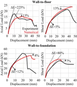
An experimental study from the literature was used to validate the high-fidelity nonlinear numerical models developed. As previously dis-cussed, due to the lack of literature data on the out-of-plane response of CLT connections, extra effort was taken to ensure that the finite element model created well captured the mechanisms observed for the connec-tion responses available in the literature, which were subjected to in- plane load conditions. Mahdavifar et al. [42] tested the connections with the nailing patterns shown in Fig. 4 on CLT panels made of Douglas- Fir. The specimens had the dimensions shown in Fig. 2. Each connection was subjected to in-plane axial and shear load conditions (shown in
Fig. 2). More details on this experimental study can be found elsewhere
[42].
The results yielded a good agreement with the experimental response, as shown by the numerical-experimental comparison in Fig. 5. The calculated axial responses were able to accurately capture the nonlinear stages of the experimentally observed behavior. A softer stiffness was calculated by the axial models, which can be attributed to the uncertainties in both the material properties of the wood panel and the determination of the parameters of the nail’s axial withdrawal
model. The calculated shear responses were able to accurately predict the stiffness in the wall-to-floor model while slightly overestimating it for the wall-to-foundation connection. This phenomenon can be attrib-uted to the higher experimental flexibility resultant of, for example, the top flange of the steel C-section used as foundation versus the perfectly fixed foundation steel plate used in the numerical model. Under shear load, convergence difficulties prevented the calculation of the post-peak response, as shown in Fig. 5.
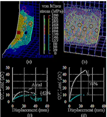
The developed models were also able to capture the failure mecha-nisms. As reported in Mahdavifar et al. [42], for the axial load condition, the wall-to-floor connection failure occurred due to damage on the floor side of the connection caused by the axial withdrawal of the nails. This failure mechanism started at the nails closest to the wall and propagated towards the nails further away from the wall as the axial load increased as shown in Fig. 6a (the von Mises stress is the square-root of a sum of stress values squared; therefore, it is a positive scalar quantity). The wall-to-foundation connection failure occurred due to the rupture of the steel connector around the bolt holes on the floor side of the connection with minimal damage on the wall side as shown in Fig. 6c. In Fig. 6c, the anchor bolts are omitted due to their significantly larger yield strength as compared to that of the angle bracket and the nails. This omission is also present in all other figures that show the failure stress condition of the wall-to-foundation connection to improve the visualization of the stresses in the angle bracket and the nails. For the shear load condition, both connections failed in similar ways: the crushing of the wood fibers in contact with the nail shanks on the wall side of the connection led to the bending of the nail shanks and subsequent formation of plastic hinges as shown in Fig. 6b and Fig. 6d. This nail behavior formed within the topmost layer of the CLT panel and did not penetrate to the core layers.
5. Out-of-Plane behavior of CLT connections
The connection models experimentally validated in Section 4 for in- plane loads were used to develop a fundamental understanding and characterize their behavior under two out-of-plane load conditions shown in Fig. 7. The first condition is representative of the compressive pressure on the exterior walls of the building (caused by wave or wind forces) that pushes the out-of-plane CLT panel towards the interior of the structure (referred to as out-of-plane exterior, or OPE). The second condition is representative of the tensile/suction pressure exerted by a tsunami inundation (or wind) flowing around the building (or that has entered the building), pushing the out-of-plane CLT panel from the interior towards the exterior of the building (referred to out-of-plane interior, or OPI).
The numerically calculated behaviors of the connections under OPE load condition are shown in Fig. 8. When subjected to the OPE load condition, the wall panel moves towards the interior of the building, pushing the angle brackets against the lower section of the panel. As a consequence, in both wall-to-floor and wall-to-panel connections, the OPE behavior was dictated by the crushing of the wall panel’s wood
fibers onto the lower section of the angle brackets as shown in Fig. 8a
and Fig. 8b. This occurred because the fasteners on the floor side of the
connections are the primary out-of-plane shear resistant elements for both connections, which resulted in higher stresses in the wall panel around this region. In addition to the damage to the wall panel, signif-icant vertical bending of the nail shanks on the wall side of the connection was observed due to the tendency of the connection to move upwards as the OPE load increased as shown in Fig. 8a. On the other hand, no significant bending or axial withdrawal was observed in the nails or the anchor bolts on the floor side of the connections. This can be explained by the bending imposed on the angle bracket by the crushed wall panel, which causes a “push down” effect as shown in Fig. 8a. This
effect applied a downward force on the floor flange of the angle bracket that increased the friction between the floor panel and the bracket.
Fig. 8c and Fig. 8d show the force–displacement response of the
connections as compared to their axial response obtained in Section 4. The comparison with the axial response is relevant for two reasons: i) to provide a basis of comparison of the out-of-plane calculated response magnitudes; and ii) because the out-of-plane load can be thought of as an “inverted” axial load where instead of the wall panel moving upwards
in the axial load, the floor panel is moving either towards or away the wall panel in the out-of-plane load. The OPE response was significantly stiffer than the axial response for both connections and significantly stronger than the axial response for the wall-to-floor connection. Despite the load capacities of the connections under OPE load condition being Wall-to-floor
(ABR105) Wall-to-foundation(AE116) Wall side
nailing Floor side
nailing
Nails Anchor
bolt Empty nailslot Empty bolt slot
Fig. 4. Nailing patterns used in the experimental investigation.
0 10 20 30 40 50 5 10 15 20 25 Displacement (mm) 0 10 20 30 40 50Displacement (mm) Axial Load (kN) Shear Load (kN)
Wall-to-floor 0 10 20 30 40 0 10 20 30 40 10 20 30 40 50 60
Axial Load (kN) Shear Load (kN)
Displacement (mm) Displacement (mm) 13% 13% 8% 7% Experiment Numerical Wall-to-foundation ΔE=225% ΔE=5% ΔE=12% ΔE=80%
attained at an average of 40% lower displacements than under axial load, the post-peak behavior presented a favorable plateau, which re-flects the modeled post-peak compressive ductile behavior of the wood panels. The similar axial and OPE load capacities in the wall-to- foundation connection can be explained by the types of fasteners used on the floor side of the connection. The three high-strength anchor bolts fastened to the foundation steel plate provided significantly more strength against the out-of-plane movement imposed by the wall panel. The numerically calculated behaviors of the connections under OPI load condition are shown in Fig. 9. When subjected to the OPI load condition, the behavior of both connections was governed by the axial withdrawal of the nails on the wall side of the connection. This behavior is similar to the one observed under the axial load condition (discussed in detail Section 4) where the axial withdrawal of the nails on the floor side of the connection dictated the behavior of the wall-to-floor connection. It is worth noting that if the nailing pattern was the same in the wall and floor sides of the connection and the wall and floor panels were identical, the OPI and axial responses of the connections should be identical, due to the symmetry of the analysis. At the failure condition, no significant damage was observed on the floor side of the connections as shown in Fig. 9a and Fig. 9b. The OPI response was significantly weaker than the axial response as shown in Fig. 9c and Fig. 9d. This occurred due to the lower number of nails on the wall side of the con-nections compared to their floor side. Furthermore, the OPI response of the wall-to-floor connection was more ductile than that under the axial
load (i.e., 2 times higher the peak displacement) while the response of the wall-to-foundation connection had approximately the same ductility. Despite the axial withdrawal of the nails on the wall side of the connection dictating the behavior, it was observed that not all the nails used on the wall side contributed to the load capacity of the connections.
Fig. 9a and Fig. 9b show the nails that did and did not contribute to the
load capacity of the connections with solid and dashed circles, respec-tively. Only the first four nails of the ten and the first six nails of the eighteen on the wall side of the wall-to-floor and wall-to-foundation connections, respectively, contributed to the load capacity of the
)
b
(
)
a
(
(c)
(d)
von Mises
stress (MPa)
von Mises
stress (MPa)
Fig. 6.Side by side comparison of the numerical and experimental [42] behaviors under (a) axial and (b) shear load for the wall-to-floor and (c) axial and (d) shear load for the wall-to-foundation connectors.
Connectors
In-plane panel
Out-of-plane panel
Reactions
Compressive pressure
In-plane panel
Connectors
Reactions
Tensile/suction pressure
OPE load condition
OPI load condition
Out-of-plane panel
Fig. 7.OPE and OPI load conditions investigated.
Fig. 8.Numerical behavior of the wall-to-floor and wall-to-foundation con-nections under OPE load condition.
connections. This result revealed a 60% inefficiency (i.e., only 40% of the available nails contributed to the load capacity) of both connections to OPI load conditions. The comparison of the load–displacement
response of the connections under OPI and OPE load conditions (see
Fig. 8 and Fig. 9) show that the load capacity in the OPE direction was,
on average, 2.3 and 1.7 times higher than the OPI for the wall-to-floor and wall-to-foundation connectors, respectively.
6. Influence of key connection design parameters on the out-of- plane behavior
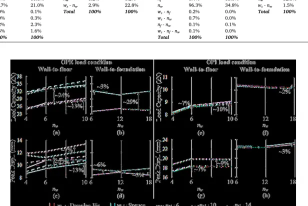
A numerical investigation with 48 models under the two out-of-plane load conditions was performed to study the influence of three key connection design parameters on the behaviors of each connection. Half of the models were subjected to OPE load conditions while the other half were subjected to OPI load conditions. Each model employed a different combination of the levels of the analyzed key connection design pa-rameters shown in Fig. 10. The behavior of each model was assessed based on the engineering demand parameters (EDP) of load capacity and peak displacement. The influence of the key connection design param-eters was identified and quantified based on the analysis of variance (ANOVA), which is a useful method to assess the statistical significance
of the variation of the calculated EDPs due to the changes in single or multiple parameters [53]. The analysis of variance relies on partitioning the total variability of the collected dataset, which is measured as the total sum of squares of the dataset, into components associated with each considered parameter. The contributions of each parameter and their respective interactions are then determined as the percentage of their associated components relative to the total sum of squares. Table 1 numerically presents the ANOVA analysis results, where the single parameter contributions represent the sensitivity of the results to the change on that single parameter while the two- and three-parameter contributions represent the sensitivity of the results to the interaction of two or more parameters [53]. Fig. 11 visually presents the calculated EDP values for each combination of the key connection design param-eters considered.
6.1. Influence on the OPE behavior
For the load capacity of the wall-to-floor connection, the analysis results indicate that the ws and nw parameters had the most significant contribution to the behavior with 98.1% of the total variability (see
Table 1). The calculated contribution of ws was significantly higher than
that of nw, making the load capacity more sensitive to the change in ws as shown in Fig. 11a. For the load capacity of the wall-to-foundation connection, the ws parameter alone had the most significant contribu-tion to the behavior with 96.9% of the total variability (see Table 1 and
Fig. 11b). The increase in load capacity due to the changing in ws from
Spruce to Douglas-Fir (indicated in Fig. 11a and Fig. 11b) was roughly correlated to the 30% difference in their compressive strength. These results are physically confirmed by the calculated failure mode which, for both connections, was primarily governed by the crushing of the wall panel’s wood fibers. For the wall-to-floor connection, the failure mode
was secondarily dictated by the bending of the nail shanks on the wall side of the connection. These failure modes were discussed in more detail in Section 5 (see Fig. 8a and Fig. 8b) and were observed for all combinations of key connection design parameters investigated. Based on these results, ws was the most influential parameter for the OPE load capacity of both connections.
For the peak displacement of the wall-to-floor connection, the analysis results indicate that the nw, nf, and ws parameters had the most significant contribution to the behavior with 95.7% of the total vari-ability (see Table 1). The calculated contribution of nf was much higher than that of nw and ws, which resulted in a higher influence of nf on the peak displacement of the wall-to-floor connection. Fig. 11c shows that nf only significantly influenced the peak displacement at its lowest level (i. e., six nails) while no significant influence occurred at subsequent nf levels. For the peak displacement of the wall-to-foundation connection, the ws parameter and the ws - nw interaction had the most significant contribution to the behavior with 99.8% of the total variability (see
Table 1). Fig. 11d, however, shows that the effective influence of these
parameters on the peak displacement of the connection was negligible. These results are physically confirmed by the fasteners on the floor side Fig. 9. Numerical behavior of the wall-to-floor and wall-to-foundation
con-nections under OPI load condition.
Wall side nails (nw) 6 10 14 4 6 10 6 12 18 Floor side nails (nf) Wall-to-floor Wall-to-foundation
Wood species (ws) Douglas-Fir, Spruce Parameter
Load conditions OPE, OPI
of the connections, which were the primary out-of-plane shear resistant elements. Consequently, for the wall-to-floor connection, the lowest level of nf increased the bearing stresses that each nail imposed on the wood panel, which resulted in larger deformations. For the wall-to- foundation connection, no significant influence was calculated for the peak displacement because the anchor bolts were significantly stronger, rigidly attached to the foundation steel plate, and not part of the nu-merical investigation.
6.2. Influence on the OPI behavior
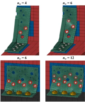
For the load capacity of the wall-to-floor connection, the analysis results indicate that the nw parameter alone had the most significant contribution to the behavior with 96.3% of the total variability. This result is shown in Fig. 11e, where all the lines are approximately con-current. For the wall-to-foundation connection, the nw and ws parame-ters had the most significant contribution to the behavior with 98.4% of the total variability (see Table 1). Fig. 11f, however, shows that the effective influences of these parameters on the load capacity of the connection were negligible. These results are physically confirmed by the calculated failure mode which, for both connections, was primarily dictated by the axial withdrawal of the nails on the wall side of the connection. Furthermore, the numerical investigation revealed that despite the level of nw used in the connections, only the four and six nails that were closer to the bend line of the angle bracket contributed to the load capacity of the wall-to-floor and wall-to-foundation connections, respectively. As a result, Fig. 11e indicates a marginal increase in load
capacity at nw levels above four nails for the wall-to-floor connection while Fig. 11f indicates no significant increase in load capacity at nw levels above six nails for the wall-to-foundation connection. Fig. 12 shows the nails that did and did not contribute to the load capacity of the connections with solid and dashed circles, respectively. In Fig. 12, the stresses were omitted to improve visualization; in addition, the re-sponses of the wall-to-floor connection with nw =10 and the wall-to- foundation connection with nw =18 are shown in Fig. 8c and Fig. 8d. These results support two important conclusions: (i) nw was the most influential parameter for the load capacity of both connections, and (ii)
not all of the available nails on the wall side of the connection contributed to the load capacity of the connection.
For the peak displacement of the wall-to-floor connection, the analysis results indicate that the nf and nw parameters had the most significant contribution to the behavior with 98.8% of the total vari-ability (see Table 1). The calculated contribution of nf was double the contribution of nw, which resulted in a higher influence of nf on the peak displacement of the connection, as shown in Fig. 11g. The contribution of nf and nw was only significant, however, at their respective lowest levels while no significance occurred at subsequent levels. For the peak displacement of the wall-to-foundation connection, the analysis results indicate that the ws and nw parameters had the most significant contri-bution to the behavior with 99.8% of the total variability (see Table 1).
Fig. 11h, however, shows that their effective influences on the peak
displacement were negligible. The influence of nw is physically confirmed by the contribution of only part of the nails on the wall side of the connection to the behavior, as discussed for the load capacity of the Table 1
ANOVA results for the OPE and OPI load conditions.
OPE load condition OPI load condition
Wall-to-floor Wall-to-foundation Wall-to-floor Wall-to-foundation
Contribution Contribution Contribution Contribution
Param. Load Capac. Peak Disp. Param. Load Capac. Peak Disp. Param. Load Capac. Peak Disp. Param. Load Capac. Peak Disp.
ws 80.4% 13.9% ws 96.9% 77.0% ws 2.1% 0.0% ws 16.3% 19.6% nf 0.1% 60.8% nw 0.2% 0.2% nf 0.4% 65.0% nw 82.1% 80.2% nw 17.7% 21.0% ws - nw 2.9% 22.8% nw 96.3% 34.8% ws - nw 1.5% 0.2% ws - nf 1.0% 0.1% Total 100% 100% ws - nf 0.2% 0.0% Total 100% 100% ws - nw 0.0% 0.3% ws - nw 0.7% 0.0% nf - nw 0.2% 2.3% nf - nw 0.1% 0.1% ws - nf - nw 0.5% 1.6% ws - nf - nw 0.1% 0.0% Total 100% 100% Total 100% 100%
connections. In addition, the influence of nf in the wall-to-floor connection is explained by the fasteners on the floor side of the connection, which were the primary out-of-plane shear resistant ele-ments. Consequently, the lowest level of nf increased the bearing stresses imposed by each nail in the wood panel and resulted in larger deformations.
7. Simplified equations and procedures
7.1. A simplified equation for estimating the OPE load capacity
The crushing of the wall panel’s wood fibers onto the lower section of
the angle brackets was the dominant failure mode for the wall-to-floor and wall-to-foundation connections under OPE load condition, as dis-cussed in Section 5 and Section 6.1. Further analysis of the failure con-ditions indicated that, for each combination of connection and wood species studied, the crushing occurred throughout the entire length of the connection (Lc in Fig. 13a) and at approximately the same distance from the bend line of the angle bracket (λHc in Fig. 13a), called herein the crushing distance. Benefiting from this finding, a simplified equation is proposed to estimate the load capacity of wall-to-floor and wall-to- foundation CLT connections (see Eq. (3)). The equation is based on the product of the compressive strength of the wood species of the wall panel in the direction of the OPE load (fc,w) by the rectangular area of
sides Lc and λHc. Since the properties of the wood species and the ge-ometry of the connection is usually known, the λ factor is derived in this study based on the statistical analysis of the results of the numerical investigation conducted in Section 6.1. Fig. 13b and Fig. 13c show, for both connections, the ratio of the calculated load capacity of each examined connection configuration over the crushing force using the entire height of the connection (i.e., λ =1.0 in Eq. (3)). The λ factor was then obtained as the average of the dataset for each connection and wood species studied. Fig. 13b and Fig. 13c also indicate that the crushing distance is, on average, 13% greater for softer wood species (Spruce in this study), and 18% greater for the wall-to-floor connection. The coefficient of variation (COV), which is a measure of the dispersion of the dataset around the average value, was calculated and shown in
Fig. 13b and Fig. 13c. The calculated COVs are well within 10% of the
average for all the connections and wood species studied. Thus, the λ factors shown in Fig. 13b and Fig. 13c are a good representation of the dataset and appropriate for use in Eq. (3) to obtain reliable estimations of the load capacity under the OPE load condition.
POOPE=λHcLcfc,w (3)
7.2. A mechanics-based simplified procedure for quantifying the nail contribution to the OPI load capacity
The axial withdrawal of the nails on the wall side of the connections was the dominant failure under the OPI load condition. Further analysis of the failure conditions indicated that there was a maximum distance from the bend line of the angle bracket, called herein the withdrawal influence distance (dwid), that dictated which nail contributed to the load capacity of the connection, as discussed in Section 5 and Section 6.2. Thus, a mechanics-based simplified procedure is proposed to determine dwid and enable the quantification of the nail contribution to the OPI load capacity of the connections. The procedure is based on the bending stiffness of the flange of the angle bracket experiencing withdrawal and the axial withdrawal stiffness of the nails. The objective is to determine the distance from the bend line of the angle bracket in which the aggregated axial withdrawal stiffness of the nails (∑nKax) exceeds the bending stiffness of the angle bracket (Kb) as illustrated in Fig. 14a. For this purpose, the flange of the angle bracket experiencing the with-drawal is idealized as a fixed cantilever beam with bending stiffness of 3EI/di3, where E is the modulus of elasticity of the angle bracket’s steel; I is the corresponding inertia of the flange of the angle bracket experi-encing withdrawal; and di is the position of nail i measured from the bend line of the angle bracket (see Fig. 14a). The procedure is comprised of two simple steps summarized in Fig. 14b. At the start of the proced-ure, the index i is set to 1, which refers to the closest nail to the bend line of the angle bracket as shown in Fig. 14a. In step 1, the bending stiffness of the angle bracket (3EI/d3) and the aggregated axial withdrawal stiffnesses of the nails at position i (∑nKax) are equated and solved for d as shown in Fig. 14b. In step 2, the calculated value of d and di are compared; if d >di, the index i is incremented by 1, which refers to the
n
w= 4
n
w= 6
n
w= 6
n
w= 12
Fig. 12.Nails that did and did not contribute to the OPI behavior of the connections.
Fig. 13.(a) Failure mode of the connections under OPE load condition (repeated from Fig. 8) and the λ factor calculation for the (b) wall-to-floor and (c) wall-to- foundation connections.
next closest nail to the bend line of the angle bracket, and steps 1 and 2 are performed again (see Fig. 14b). This process is repeated until d ex-ceeds the ith nail position, in which case dwid is determined as di-1 – in
other words, the last nail position at which step 2 results in a “yes”
condition. The nails positioned at a distance within dwid from the bend line of the angle bracket are the ones that contribute to the load capacity of the connection under the OPI load condition.
To verify the accuracy of the procedure, dwid was calculated for the wall-to-floor and wall-to-foundation connections previously investi-gated. Table 2 shows the calculated values of dwid, the number of nails in the angle bracket within this distance, and the number of nails that contributed to the load capacity of the connections under OPI load condition. The results indicate that the proposed method was able to accurately predict which nails contributed to the load capacity of the connections when subjected to the OPI load condition.
8. Conclusions
CLT wall-to-floor and wall-to-foundation connections were studied in order to understand and characterize their behavior under two out-of- plane load conditions. The first condition is representative of the compressive pressure (referred to as OPE) and the second condition is representative of the tensile/suction pressure (referred to as OPI) on the exterior wall of the building. It was observed that the behaviors of the connections were significantly different in the OPE and OPI load con-ditions. The OPE behavior was dictated by the crushing of the wall panel’s wood fibers onto the lower section of the angle brackets and
resulted in a stiff pre-peak with a ductile post-peak behavior. The OPI behavior was dictated by the axial withdrawal of the nails on the wall side of the connection and resulted in a softer pre-peak with a softening post-peak behavior. The load capacity under the OPE load condition was, on average, 2.3 and 1.7 times higher than under the OPI load condition for the wall-to-floor and wall-to-foundation connectors, respectively.
A numerical investigation with 48 models was performed and the analysis of variance (ANOVA) method was used to quantify the influence of three key connection design parameters (i.e., the number of nails on the wall side of the connection, nw, the number of nails on the floor side of the connection, nf, and the wood species, ws) on the out-of-plane behavior of the connections. The results support the following conclusions:
•The ws parameter was the most influential parameter for the load capacity of the connections under the OPE load condition. The change in ws from Spruce to Douglas-Fir increased the load capacity by 24% and 29%, on average, for the wall-to-floor and wall-to- foundation connections, respectively. This increase was roughly the same as the difference between the compressive strength of both wood types.
• The nf parameter was the most influential parameter for the peak displacement of the wall-to-floor connection under the OPE load condition. The lowest nf level of 6 nails increased the peak displacement by 22%, on average, in comparison to the other two nf levels of 10 and 14 nails, which resulted in approximately the same peak displacements.
• Under the OPE load condition, the crushing of the wall panel’s wood
fibers occurred throughout the entire length and at approximately the same distance from the bend line of the angle bracket. This dis-tance was referred to in this study as the crushing distance and was shown to be, on average, 13% greater for softer wood species (Spruce in this study) and 18% greater for the wall-to-foundation connection. • The results of the numerical investigation conducted in this study
were statistically analyzed to determine the crushing distance and to derive a simplified equation for estimating the OPE load capacity of the CLT connections.
• The nw parameter was the most influential parameter for the load capacity and the peak displacement of the connections under the OPI load condition. This study showed that only 40% of the nails on the wall side of the connections contributed to their OPI load capacity. This result indicated that the connections were 60% inefficient to OPI load condition and that there was a maximum distance from the bend line of the angle bracket, referred to in this study as the with-drawal influence distance, that dictated which nail contributed to the load capacity of the connection.
• A mechanics-based simplified procedure for quantifying the nail contribution to the OPI load capacity of the CLT connections was proposed based on their calculated withdrawal influence distance. The accuracy of this procedure was verified with the results of the numerical investigation conducted in this study.
Declaration of Competing Interest
The author declare that there is no conflict of interest. References
[1] United States Geological Survey (USGS). Why Are We Having so Many Earthquakes? Web Page 2016. https://www.usgs.gov/faqs/why-are-we-having-so- many-earthquakes-has-naturally-occurring-earthquake-activity-been.
[2] Toscano P. The most costly earthquakes of all time. Web Page 2011. Kb=3EI/di3
dwid
Stiffness of the connector, Kb
Aggregated withdrawal
stiffnesses of the fasteners, ∑nKax
K (a) (b) d di=1 di=2 di=3 di=4 di=5 i=1 i=2 i=3 i=4 i=5
Fig. 14.Proposed method to determine the withdrawal influence distance. Table 2
Calculated and predicted number of nails that contribute to the load capacity.
dwid
(mm) # Nails Within dwid
# Nails Contributing to Load Capacity (from analyses) Wall-to-floor 42 4 4
Wall-to-
[3] Popovski M, Gavric I. Performance of a 2-story CLT house subjected to lateral loads. J Struct Eng 2016;142:E4015006. https://doi.org/10.1061/(ASCE)ST.1943- 541X.0001315.
[4] Izzi M, Casagrande D, Bezzi S, Pasca D, Follesa M, Tomasi R. Seismic behaviour of cross-laminated timber structures: a state-of-the-art review. Eng Struct 2018;170: 42–52. https://doi.org/10.1016/j.engstruct.2018.05.060.
[5] Pei S, Popovski M, Van De Lindt JW. Seismic Design of a Multi-Story Cross Laminated Timber Building Based on Component Level Testing. World Conference on Timber Engineering (WCTE) 2012, Auckland, New Zealand: 2012, p. 244–52.
[6] Popovski M, Schneider J, Schweinsteiger M. Lateral Load Resistance of Cross- Laminated Wood Panels. World Conference on Timber Engineering (WCTE) 2010, Trento, Italy: 2010, p. 10.
[7] Reynolds T, Foster R, Bregulla J, Chang W-S, Harris R, Ramage M. Lateral-load resistance of cross-laminated timber shear walls. J Struct Eng 2017;143:06017006. https://doi.org/10.1061/(ASCE)ST.1943-541X.0001912.
[8] Pei S, van de Lindt JW, Popovski M, Berman JW, Dolan JD, Ricles J, et al. Cross- laminated timber for seismic regions: progress and challenges for research and implementation. J Struct Eng 2016;142:E2514001. https://doi.org/10.1061/ (ASCE)ST.1943-541X.0001192.
[9] Follesa M, Christovasilis IP, Vassallo D, Fragiacomo M, Ceccotti A. Seismic design of multi-storey cross laminated timber buildings according to Eurocode 8. Ingegneria Sismica Int J Earthq Eng 2013;30:27–53.
[10] Hashemi A, Valadbeigi A, Masoudnia R, Quenneville P. Seismic resistant cross laminated timber structures using an innovative resilient friction damping system. In: Proceedings of the 2016 New Zealand Society of Earthquake Engingeering Conference (NZSEE), Christchurch, New Zealand: 2016, p. 8.
[11] Joyce T, Ballerini M, Smith I. Mechanical behaviour of in-plane shear connections between CLT wall panels. In: Proceedings of the CIB Working Commission W18–Timber Structures. 44th meeting, Alghero, Italy; 2011, p. 3.
[12] Izzi M, Polastri A, Fragiacomo M. Investigating the hysteretic behavior of cross- laminated timber wall systems due to connections. J Struct Eng 2018;144: 04018035. https://doi.org/10.1061/(ASCE)ST.1943-541X.0002022. [13] van de Lindt JW, Furley J, Amini MO, Pei S, Tamagnone G, Barbosa AR, et al.
Experimental seismic behavior of a two-story CLT platform building. Eng Struct 2019;183:408–22. https://doi.org/10.1016/j.engstruct.2018.12.079.
[14] Ceccotti A, Sandhaas C, Okabe M, Yasumura M, Minowa C, Kawai N. SOFIE project - 3D shaking table test on a seven-storey full-scale cross-laminated timber building. Earthq Eng Struct Dyn 2013;42:2003–21. https://doi.org/10.1002/eqe.2309.
[15] Service NW. Pacific Tsunami warning center – frequent asked questions. Web Page 2019.
[16] Mimura N, Yasuhara K, Kawagoe S, Yokoki H, Kazama S. Damage from the Great East Japan Earthquake and Tsunami – a quick report. Mitig Adapt Strat Glob
Change 2011;16:803–18. https://doi.org/10.1007/s11027-011-9297-7.
[17] Kajitani Y, Chang SE, Tatano H. Economic Impacts of the 2011 Tohoku-Oki Earthquake and Tsunami. Earthq Spectra 2013;29:S457–78. https://doi.org/
10.1193/1.4000108.
[18] Goda K, Petrone C, De Risi R, Rossetto T. Stochastic coupled simulation of strong motion and tsunami for the 2011 Tohoku, Japan earthquake. Stoch Env Res Risk Assess 2017;31:2337–55. https://doi.org/10.1007/s00477-016-1352-1.
[19] American Society of Civil Engineers (ASCE). Minimum design loads and associated criteria for buildings and other structures. ASCE 7 Publication 2017:889. [20] Federal Emergency Management Agency (FEMA). Guidelines for Design of
Structures for Vertical Evacuation from Tsunamis. Second Edition. FEMA P-646 Publication 2012:202. https://doi.org/10.1061/40978(313)7.
[21] Yeh H, Barbosa AR, Ko H, Cawley J. Tsunami loadings on structures. Coast Eng 2014:1–13.
[22] Poulin M, Viau C, Lacroix DN, Doudak G. Experimental and analytical investigation of cross-laminated timber panels subjected to out-of-plane blast loads. J Struct Eng 2018;144:04017197. https://doi.org/10.1061/(ASCE)ST.1943-541X.0001915. [23] Mahdavifar V, Barbosa AR, Sinha A. Nonlinear Layered Modelling Approach for
Cross Laminated Timber Panels Subjected to Out-Of-Plane Loading. 41st IAHS. Algarve, Portugal: World Congress; 2016. p. 9.
[24] Fragiacomo M, Menis A, Clemente I, Bochicchio G, Ceccotti A. Fire resistance of cross-laminated timber panels loaded out of plane. J Struct Eng 2013;139: 04013018. https://doi.org/10.1061/(ASCE)ST.1943-541X.0000787.
[25] Chen Y, Lam F. Bending performance of box-based cross-laminated timber systems. J Struct Eng 2013;139:1–12. https://doi.org/10.1061/(ASCE)ST.1943-
541X.0000786.
[26] Hristovski V, Dujic B, Stojmanovska M, Mircevska V. Full-scale shaking-table tests of XLam panel systems and numerical verification: Specimen 1. J Struct Eng 2013; 139:2010–8. https://doi.org/10.1061/(ASCE)ST.1943-541X.0000754.
[27] Fragiacomo M, Dujic B, Sustersic I. Elastic and ductile design of multi-storey crosslam massive wooden buildings under seismic actions. Eng Struct 2011;33: 3043–53. https://doi.org/10.1016/j.engstruct.2011.05.020.
[28] Izzi M, Flatscher G, Fragiacomo M, Schickhofer G. Experimental investigations and design provisions of steel-to-timber joints with annular-ringed shank nails for
cross-laminated timber structures. Constr Build Mater 2016;122:446–57. https:// doi.org/10.1016/j.conbuildmat.2016.06.072.
[29] Rinaldin G, Amadio C, Fragiacomo M. A component approach for the hysteretic behaviour of connections in cross-laminated wooden structures. Earthquake Eng Struct Dyn 2013;42:2023–42. https://doi.org/10.1002/eqe.2310.
[30] Ceccotti A, Sandhaas C, Yasamura M. Seismic Behaviour of Cross-Laminated Timber Buildings. Proceedings of the International Convention of Society of Wood Science and Technology and United Nations Economic Commission for Europe –
Timber Committee, Geneva, Switzerland: 2010, p. 14.
[31] Gavric I, Fragiacomo M, Popovski M, Ceccotti A. Behaviour of Cross-Laminated Timber Panels under Cyclic Loads. In: Aicher S, Reinhardt H, Garrecht H, editors. Materials and Joints in Timber Structures, Dordrecht: RILEM Bookseries, vol 9. Springer; 2014, p. 689–702. https://doi.org/10.1007/978-94-007-7811-5_62.
[32] Huber JAJ, Ekevad M, Girhammar UA, Berg S. Finite element analysis of alternative load paths in a platform-framed CLT building. Proc Inst Civil Eng –
Struct Build 2020;173:379–90. https://doi.org/10.1680/jstbu.19.00136.
[33] Bedon C, Rinaldin G, Fragiacomo M, No´e S. q-factor estimation for 3D log-house
timber buildings via finite element analyses. Soil Dyn Earthquake Eng 2019;116: 215–29. https://doi.org/10.1016/j.soildyn.2018.09.040.
[34] Rinaldin G, Fragiacomo M. Non-linear simulation of shaking-table tests on 3- and 7-storey X-lam timber buildings. Eng Struct 2016;113:133–48. https://doi.org/
10.1016/j.engstruct.2016.01.055.
[35] Li M, Lam F. Lateral Behaviour of Cross Laminated Timber Shear Walls under Reversed Cyclic Loads. In: Proceedings of the Tenth Pacific Conference on Earthquake Engineering; 2015. p. 1–8.
[36] Pozza L, Saetta A, Savoia M, Talledo D. Angle bracket connections for CLT structures: experimental characterization and numerical modelling. Constr Build Mater 2018;191:95–113. https://doi.org/10.1016/j.conbuildmat.2018.09.112.
[37] Pozza L, Saetta A, Savoia M, Talledo D. Coupled axial-shear numerical model for CLT connections. Constr Build Mater 2017;150:568–82. https://doi.org/10.1016/j.
conbuildmat.2017.05.141.
[38] Schneider J, Karacabeyli E, Popovski M, Stiemer SF, Tesfamariam S. Damage assessment of connections used in cross-laminated timber subject to cyclic loads. J Perform Constr Facil 2014;28:371–6. https://doi.org/10.1061/(ASCE)CF.1943-
5509.0000528.
[39] Mahdavifar V, Sinha A, Barbosa AR, Muszynski L, Gupta R. Lateral and withdrawal capacity of fasteners on hybrid cross-laminated timber panels. J Mater Civ Eng 2018;30:04018226. https://doi.org/10.1061/(ASCE)MT.1943-5533.0002432. [40] Danielsson H, Jelec M, Serrano E. Strength and Stiffness of Cross Laminated Timber
at In-Plane Beam Loading. Sweden: Lund; 2017.
[41] Gavric I, Fragiacomo M, Ceccotti A. Cyclic behaviour of typical metal connectors for cross-laminated (CLT) structures. Mater Struct 2015;48:1841–57. https://doi.
org/10.1617/s11527-014-0278-7.
[42] Mahdavifar V, Barbosa AR, Sinha A, Muszynski L, Gupta R, Pryor SE. Hysteretic response of metal connections on hybrid cross-laminated timber panels. J Struct Eng 2019;145:04018237. https://doi.org/10.1061/(ASCE)ST.1943-
541X.0002222.
[43] Weinfurt KP. Multivariate Analysis of Variance. Reading and Understanding Multivariate Statistics: American Psychological Association; 1995. p. 245–76. [44] Corp Simulia. ABAQUS User’s Manual. 2019 Edition. Providence, RI: Dassault
Syst`emes; 2019.
[45] Izzi M, Polastri A, Fragiacomo M. Modelling the mechanical behaviour of typical wall-to-floor connection systems for cross-laminated timber structures. Eng Struct 2018;162:270–82. https://doi.org/10.1016/j.engstruct.2018.02.045.
[46] Hong J, Barrett D. Three-dimensional finite-element modeling of nailed connections in wood. J Struct Eng 2010;136:715–22. https://doi.org/10.1061/
(ASCE)ST.1943-541X.0000160.
[47] Hassanieh A, Valipour HR, Bradford MA, Sandhaas C. Modelling of steel-timber composite connections: validation of finite element model and parametric study. Eng Struct 2017;138:35–49. https://doi.org/10.1016/j.engstruct.2017.02.016.
[48] Johansen KW. Theory of timber connections. Int Assoc Bridge Struct Eng 1949;9: 249–62. https://doi.org/10.5169/seals-9703.
[49] European Committee for Standardization (CEN). Eurocode 5: Design of timber structures: Part 1-1, General–Common rules and rules for buildings. EN 1995-1-1:
2004+A1:2008 Publication 2008:121.
[50] American Wood Council (AWC). National Design Specification® for Wood Construction, 2018 Edition. NDS 2018 Publication 2017:193.
[51] Uibel T, Blaß H. Edge Joints With Dowel Type Fasteners in Cross Laminated Timber. Proceedings of the CIB-W18 Meeting 2007, Bled, Slovenia: 2007, p. 11. [52] Brandner R, Flatscher G, Ringhofer A, Schickhofer G, Thiel A. Cross laminated
timber (CLT): overview and development. Eur J Wood Wood Prod 2016;74: 331–51. https://doi.org/10.1007/s00107-015-0999-5.
[53] Montgomery DC. Design and Analysis of Experiments. 10th ed. Hoboken, NJ: John Wiley & Sons, Inc.; 2019.
![Fig. 6. Side by side comparison of the numerical and experimental [42] behaviors under (a) axial and (b) shear load for the wall-to-floor and (c) axial and (d) shear load for the wall-to-foundation connectors](https://thumb-us.123doks.com/thumbv2/123dok_us/9533971.2437382/5.892.469.828.505.889/comparison-numerical-experimental-behaviors-axial-shear-foundation-connectors.webp)