© 2017, IRJET | Impact Factor value: 5.181 | ISO 9001:2008 Certified Journal | Page 82
EFFECT OF TOOL GEOMETRY ON THE PERFORMANCE OF EDM
Paridhi Malhotra
1, Himank Ambashta
2,Charanjeev Mehndiratta
3, Lakshay Sachdeva
41
Asst Prof, Dept. of Mechanical Engineering, Manav Rachna International University, Haryana, India
2,3,4
Student, Dept. of Mechanical Engineering, Manav Rachna International University, Haryana, India
---***---Abstract
— EDM is the modern machining method whichencounters the problem of high TWR and Low MRR therefore our vision is to increase the efficiency of machining process which can be achieved by modifying the tool geometry and introducing the Air Compressor unit, thereafter enhancing the performance of EDM. In this paper, we explained the work in the development of die-sinking EDM for the improvement of machining characteristics. We investigated the optimum process parameters of EDM on EN19 steel alloy material with EDM oil as a dielectric fluid for solid and air assisted rotary electrode having three holes. We studied the effect of process parameters such as pulse current, rpm, duty cycle on Tool wear rate and Material removal rate for air assisted rotary electrode having three-hole processes as well as on conventional EDM process Three different levels of discharge current, rpm, duty cycle levels of pulse on time have been selected for investigation.
Key Words: Three Holed electrode tool, Solid electrode tool, Air compressing Unit, MRR, TWR
1.INTRODUCTION
Electrical Discharge Machine (EDM) is especially used for the manufacturing of 3-D complex geometry and hard material parts that are extremely difficult-to- machine by conventional machining processes. Its ability to control the process parameters to achieve the required dimensional accuracy and finish has placed this machining operation in a prominent position in industrial applications.[1] In a conventional Die-Sinking EDM machine the manufacturing process the desired shape is obtained by using electrical discharges (sparks). Material is removed from the work piece by a series of rapidly recurring current discharges between two electrodes, separated by a dielectric liquid and subject to an electricvoltage. One of the electrodes is called the tool-electrode, or simply the "tool" orthe other is called the work piece-electrode, or "work piece. “This conventional
.
method shows the disadvantages of having high tool wear rate and lower material removal rate due to which it increases machining time and offers less efficiency. [2] In EDM, since there is no direct contact between the work piece and the electrode, hence there are no mechanical forces existing between them. Any type of conductive material can be machined using EDM irrespective of the hardness or toughness of the material.
2. MATERIAL SELECTION AND FABRICATION
2.1
Tool
The selection of the most appropriate electrode material is a key decision in the process plan for any sinking EDM job. [3] The important variables to be considered for selection of electrode material are material removal rate, tool wear rate, surface roughness, machinability and material cost therefore we choose electrolytic copper rod[4] with three holes drilled in it.
2.1.1
Manufacturing of Tool
The manufacturing of the tool involved a series of steps on the Copper rod:[5]
The rod was first subjected to turning operation to obtain the rough dimensions.
The body of the tool is drilled using 2 mm drill and a blind hole drilled which will serve as the passage for the compressed air.
Then, on the side wall three holes are drilled of 2 mm diameter.
Wall of the tool is externally turned to 12 mm. This is done in stages and with a wooden support inside the electrode because copper used to get extremely hot and there were chances of the bending of the tool.
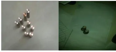
[image:1.595.338.527.579.664.2] Finally, the finishing operation is done to obtain the finish required with the tolerances.
Figure 1: EDM electrodes with no hole and 3-holes
2.2
Work pieces
© 2017, IRJET | Impact Factor value: 5.181 | ISO 9001:2008 Certified Journal | Page 83
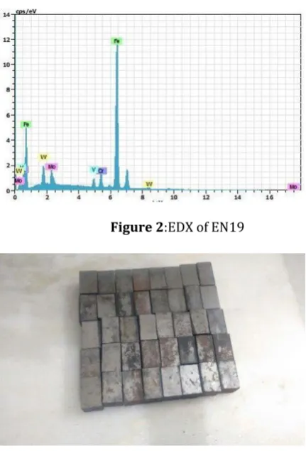
Table 1:Chemical composition analysis in % of Work piece
C V Cr Mo W Fe
0.99 2.06 4.21 5.03 6.10 Rest
2.2.1 Characterization of Work Piece
[image:2.595.52.269.125.174.2]Work piece is characterized by performing EDX. This is done in order to have the data collected as a reference to measure the performance of process. [6]
[image:2.595.54.270.228.546.2]Figure 2:EDX of EN19
Figure 3:Identical Workpieces
3. SELECT RESPONSE VARIABLE
Based on the basic characteristics of EDM, machining parameters are selected which are varied as per the orthogonal array. We have selected four machining parametersfor the experiment which results in a L9
orthogonal array. [7]
Discharge Current(A)
Pulse on time (μs) (Ton)
Duty cycle (dc)
Rotation (rpm)
Table is given below showing levels of each parameters.
Table 2:L9 Array of Experiments
SNo. Current TON D.C RPM
1
3
100 0.56 200
2
3
300 0.64 500
3
3
500 0.72 800
4
5
100 0.64 800
5
5
300 0.72 200
6
5
500 0.56 500
7
7
100 0.72 500
8
7
300 0.56 800
9
7
500 0.64 200
4.RESULTS AND DISCUSSION
The results are calculated for each experiment set as mention in Table 2. Solid and 3-hole electrode are the types tool electrode have been used. Hence, two types of flushing methods have been applied i.e. jet and through flushing for solid and 3- hole electrode respectively. The MRR, TWR and %electrode wear are calculated for each case.
4.1 Material Removal Rate
Table 3:MRR of Work pieces machined with solid tool
S No initial wt. final wt. MRR
1 74.7255 74.6069 0.1186
2 59.7612 59.6804 0.0808
3 71.061 71.0103 0.507
4 63.1816 62.9101 0.2715
5 71.9841 71.8112 0.1729
6 59.7211 59.1481 0.573
7 84.9552 84.763 0.1922
8 67.5381 67.3402 0.1979
9 73.9744 73.8866 0.878
Table 4: MRR of Work pieces machined with 3- holed tool
S No initial wt. final wt. MRR
1 62.7165 62.6011 0.1154
2 62.6569 62.5955 0.0614
3 69.7315 69.6925 0.039
4 59.6183 59.4114 0.2069
5 64.5881 64.4079 0.1802
6 65.0377 64.9607 0.077
7 66.2305 65.5826 0.6479
8 74.7604 74.5982 0.1622
[image:2.595.332.534.450.575.2]© 2017, IRJET | Impact Factor value: 5.181 | ISO 9001:2008 Certified Journal | Page 84
Figure 4: Comparison between MRR produced with solid tool and 3-holed tool
7 5 3 0.6 0.5 0.4 0.3 0.2
500 300 100
0.72 0.64 0.56 0.6 0.5 0.4 0.3 0.2
800 500 200 Current
M
e
a
n
o
f
M
e
a
n
s
Ton
DC RPM
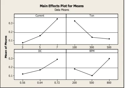
[image:3.595.53.266.101.271.2]Main Effects Plot for Means Data Means
Figure 5:MRR Graph plotted for mean for EDM process with solid electrode
7 5 3 0.3
0.2
0.1
500 300 100
0.72 0.64 0.56 0.3
0.2
0.1
800 500 200 Current
M
e
a
n
o
f
M
e
a
n
s
Ton
DC RPM
Main Effects Plot for Means Data Means
Figure 6: MRRGraph plotted for mean for EDM process with 3-holed electrode
It can be clearly perceived from the graph that as the current increases mean, the value of MRR also increases because of
an increase in the discharge energy in machining zone resulted in more melting and evaporation of materials. An air assisted three-holed tool with rotation surges the hydrostatic pressure variation in discharge gap and hence an immense drop in pressure excites additional molten metal to be dispatched from the crater. [8] The crater size is larger in air compressor assisted EDM, because there is an additional heat other than the heat input by the spark. Also, increase of plasma channel is observed due to prolonged pulse on time, hence the energy density decreases resulting in the occurrence of marginal melting and vaporization of work piece. This reduces the MRR at prolonged pulse-on time. MRR improves with a rise in duty cycle because at higher value of duty cycle, high spark energy generated which causes more molten and evaporation of material from the work piece and thus MRR in air assisted three-holed tool EDM process is more than solid tool EDM process. [9] Also, the injection of compressed air contributes in faster removal of melted and vaporize material, hence resulting in more efficient flushing of eroded particles from the machining gap.Therefore, we can have concluded that MRR in air assisted EDM process is more than the three-holed tool EDM and solid tool EDM process.
[image:3.595.53.270.322.500.2]A. Tool Wear Rate
Table 5: TWR of work pieces machined with solid tool
Table 6: TWR of work pieces machined with 3-holed tool
S No initial wt. final wt. TWR
1
51.3577 53.5572
-0.0133
2
50.2665 50.3655
-0.0066
3
49.6716 49.85005 -0.01123
451.2267 51.23105 -0.00029
550.6661 50.69505 -0.00227
648.5041 48.51325 -0.00061
7
52.2517 52.3282
-0.0051
8
51.2642 51.3017
-0.0025
9
49.6752 49.78485 -0.00731
S No. initial wt. final wt. TWR
1 27.4492 27.6997 -0.0167 2 29.0000 29.11205 -0.00747
3 28.6521 28.8780 -0.01506
4 28.1131 28.14295 -0.00199
5 29.0465 29.0942 -0.00318
6 29.0266 29.0563 -0.00198
7 28.9111 29.03211 -0.008013 8 28.8821 28.9448 -0.00418
[image:3.595.341.530.429.574.2] [image:3.595.55.271.551.702.2]© 2017, IRJET | Impact Factor value: 5.181 | ISO 9001:2008 Certified Journal | Page 85
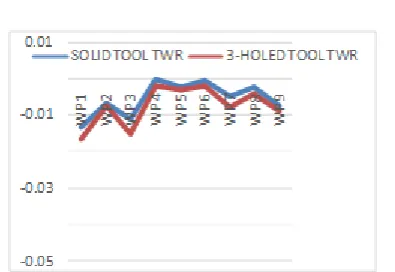
Figure 7: Comparison between TWR produced with solid tool and 3-holed tool
7 5 3 0.015 0.010 0.005 500 300 100 0.72 0.64 0.56 0.015 0.010 0.005 800 500 200 Current M e a n o f M e a n s Ton DC RPM
[image:4.595.45.278.476.629.2]Main Effects Plot for Means Data Means
Figure 7:TWR Graph plotted for mean for EDM process with Solid electrode
7 5 3 0.007 0.006 0.005 0.004 0.003 500 300 100 0.72 0.64 0.56 0.007 0.006 0.005 0.004 0.003 800 500 200 Current M e a n o f M e a n s Ton DC RPM
Main Effects Plot for Means Data Means
Figure 98:TWR Graph plotted for mean for EDM process with 3-holed electrode
Increase in current increases accumulation of eroded particles at the discharge gap, which causes a more wear on the tool electrode. TWR has been found to have an inverse relation with pulse duration probably because the temperature of the electrode surface reduces significantly
as
athe plasma channel expands at higher values of pulse duration. [10] The black carbon layer emitted due to decomposition of dielectric is deposited on the electrode
surface for longer pulse duration which produces resistance against the wear of the electrode. Further, it can be depicted that TWR is lower in the Three-holed tool EDM process than the conventional solid tool EDM process. It can be possibly explained as due to long pulse duration, compressed air in multi holed EDM process facilitates faster removal of heat which reduces the temperature around the surface of tool electrode, resulting in lower TWR. [11]
5.CONCLUSION
An investigation is made to compare MRR and TWR of Solid tool with Air Assisted three-holed EDM witnessing the parameters; Discharge Current(A), Pulse on time (μs) (Ton), Duty cycle (dc), Rotation(rpm). The following conclusions have been drawn through this investigation:
1. Clearly 3-holed electrode tool assisted with air compressor unit possess higher MRR and lower TWR when compared to solid tool as it can flush the eroded particles from the surface of the work piece and as well the gap.
2. Increase in Pulse-on results in decreasing of MRR consistently. Consequently, with increase the MRR, reduction in Pulse-onbecomes imperative. Also as the pulse on increases, TWR increases.
3. In three-holed electrode the crater size is larger in comparison to solid electrode tool because of existence of an additional heat in addition to the heat input by the spark.
6. REFERENCES
1. Mohan Khire and Amar Bhandare “Electro Discharge Machining Studies”, LAP Lambert Academic Publishing, March 8, 2012, ISBN-10: 3848423820 ISBN-13: 978-3848423828
2. AzharEqubal, Anoop Kumar Sood, “Electrical Discharge Machining: An Overview on Various Areas of Research”, Journal of manufacturing and industrial engineering, ISSN 1339-2972 (On-line)
3. Fred L. AmorimI; Walter L. Weingaertne, “The
behavior of graphite and copper electrodes on the finish die-sinking electrical discharge machining (EDM) of AISI P20 tool steel”, J. Braz. Soc. Mech. Sci. & Eng. vol.29 no.4 Rio di Janeiro Oct./Dec. 2007,http://dx.doi.org/10.1590/S 1678-58782007000400004, ISSN 1678-5878
On-line version ISSN 1806-3691
4. E. Bud Guitrau. “The EDM Handbook”, Carl Hanser Verlag GmbH & Co, 1 December 1997, ISBN-10: 1569902429 ISBN-13: 978-1569902424
© 2017, IRJET | Impact Factor value: 5.181 | ISO 9001:2008 Certified Journal | Page 86 edition, 1 July 2017, 10: 0070965536
ISBN-13: 978-0070965539
6. P.N. Rao, “Manufacturing Technology - Vol. 2”, McGraw Hill Education; Third edition (1 July 2017), ISBN-10: 1259029565 ISBN-13: 978-1259029561
7. Elman C. Jameson, “Electrical Discharge Machining”, Society of Manufacturing Engineers, 2001, ISBN-087263521X, 9780872635210
8. Sushil Kumar Choudhary, Dr. R.S Jadoun, “Current Advanced Research Development of Electric Discharge Machining (EDM): A Review”, International Journal of Research in Advent Technology, Vol.2, No.3, March 2014 E-ISSN: 2321-9637
9. Prof. S.R. Nipanikar, “parameter optimization of electro discharge machining of AISI d3 steel material by using taguchi method”, Journal of Engineering Research and Studies, E-ISSN0976-7916
10. Harshit K. Dave1, Sudhanshu Kumar, Nipul C. Rana, Harit K. Raval, “electro discharge machining of AISI 304 using solid and bundled electrodes”, 5th International & 26th All India Manufacturing Technology, Design and Research Conference (AIMTDR 2014) December 12th–14th, 2014, IIT-Guwahati, Assam, India