© 2018, IRJET | Impact Factor value: 6.171 | ISO 9001:2008 Certified Journal | Page 3661
Development of Image Processing Technique for Preventing
Unauthorized Photography
Sonali Chavan
1, Dr. Mahesh Kumbhar
21
Student, Electronics and Telecommunication Department, Rajarambapu Institute of Technology, Maharashtra, India
2Professor, Electronics and Telecommunication Department, Rajarambapu Institute of Technology, Maharashtra, India
---***---Abstract -
Smart phones with camera are very commonthese days. While visiting places such as museums, historical monuments, temples, exhibitions or places where maintaining secrecy is a big issue, user carries his smart phone with him. This system provides the solution for this undesired photography to prevent security and privacy of the site. The system will simply detect camera in photography prohibited area and then it will emit a strong light source at each device to neutralize it from capturing image or video. It is neither a health dangerous to health nor it will affect the detected camera’s operation. This detection and deactivation method of camera or other optical device can be more useful in defense areas to identify possible attacks.
Key Words: Circular Hough transform, CCD sensor,
Digital Camera Deactivation, over-exposure, Retro-Reflection etc.
I.
INTRODUCTION
Though photography is prohibited in museums, historical monuments, temples, user tend to capture images of these sites secretly, which is not significant. Considering the Piracy at theaters, Indian film industry suffers heavy losses due to it. To avoid such problems, there is a need to develop a system which will detect any digital (DSLR) camera and then neutralize image or video taken by that camera. Film industry also suffers 1/3 loss due to movie Piracy. Hence, there arises a need to prevent this undesired photography, to avoid this heavy loss. The solution is based on detecting the camera’s that are capturing pictures of the site. Photography is banned at places such as museums, court rooms, shopping malls, industries, defense areas, jewelry stores etc. Preventing photography ensures the gift shop maintains a monopoly on selling images. Banning photography believes to boost security by preventing thieves or terrorists from visually capturing images in defense areas[3].
II.
LITERATURE REVIEW:
There are two methods for the detection of the digital camera. The first method is based on the Circular Hough Transform. Virendra Kumar Yadav et al. have presented their study in International Conference on Electronics and Communication Systems (ICECS-2014) on the “Approach to Accurate Circle Detection: Circular Hough Transform and Local Maxima Concept”. The authors wrote about method for detecting circular objects over digital
images have received considerable attention from industries for applications such as detection of target detection, inspection of manufactured products etc. Finding one or several maxima considering different accumulators simultaneously and mapping the found parameters corresponding to the maxima back to the original image is key concept of proposed algorithm[6].
The second method is based on the Retro-Reflection property of the digital camera. P. A. Dhulekar, PriyankaAher et al. has presented their work in Journal of Science and Technology (JST) in 2017 on the “Arduino based Anti-Photography System for Anti-Photography Prohibited Areas”. They have proposed the system for detecting and deactivating digital cameras in photography prohibited areas. This technique will locate a camera and then neutralize it. It uses image processing algorithms for detecting camera's lens. For the detection of the digital camera, they have used reflection method. Retro-reflection is returning light only within an extremely narrow-cone, with minimum scattering[2].
© 2018, IRJET | Impact Factor value: 6.171 | ISO 9001:2008 Certified Journal | Page 3662
III.
PROPOSED SYSTEM:
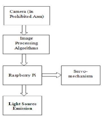
Fig-1 Block Diagram of the Proposed System
This technique is useful for detecting and deactivating digital cameras in photography prohibited areas. It consists of two parts. The first part is camera detection unit. The second part is digital image deactivating unit. Camera detection unit includes camera interfaced with PC. There is an camera in the photography prohibited area which is used to capture the image in that prohibited area. When there is an any digital camera appears in the photography prohibited area, then that digital camera is detected by using the image processing algorithms and camera in that area. The position of the lens of camera will be tracked by referring its axis value as defined in image processing algorithm.
The digital image deactivating unit consists of Raspberry Pi board, light source emission and servomechanism. Control signal from camera detection unit will be generated and sent through wireless communication to Raspberry Pi board. The Raspberry Pi board is interfaced with the MATLAB using Wi-Fi. The Raspberry Pi board will operate the servomechanism such that light source emission will point in the direction of detected lens and emit strong light source which will reduce the quality of captured image. It does not interfere with camera's operation and it is harmless to the camera user.
IV.
METHODOLOGY:
The Fig-1 shows block diagram of proposed system which consists of following parts:
A. Camera(In prohibited area):
Camera will be used as an image acquisition device for capturing images in photography prohibited areas. This camera will be interfaced with computer via image acquisition toolbox in MATLAB. The data obtained from the camera is in the form of video. It can be further divided into the frames for further processing.
Fig-2 Flow chart of the Proposed System
B. Image Processing Algorithms:
After acquisition of images from camera, image processing algorithms are used in order to find the position of the camera. In that Circular Hough Transform is used for the detection of the digital camera.
C. Raspberry Pi 3 Board:
By using the different image processing algorithms in the MATLAB, the position of the camera lens is identified and the respective control signal is given to the Raspberry Pi 3 Board. Raspberry Pi 3 Board is used to control the servomechanism.
D. Servomechanism:
It will operate as per the control signal obtained from the Raspberry Pi 3 Board. It includes the servo motors which are moved in the particular direction in order to neutralize the camera.
E. Light Source Emission:
The Strong Light Source is placed on the servo motor. So that, strong light source will focus the strong light on to the camera lens. So that the captured image will get distorted.
V.
EXPERIMENTAL RESULTS:
There are two algorithms for the detection of the camera. First algorithm is based on Circular Hough
[image:2.595.314.550.59.380.2] [image:2.595.65.251.96.303.2]© 2018, IRJET | Impact Factor value: 6.171 | ISO 9001:2008 Certified Journal | Page 3663 Transform and second algorithm based on Retro-reflective
property.
The algorithm based on the Circular Hough Transform consists of detection of objects having circular shapes in digital images is important for image analysis. It relies on the equation of circle. In that, minimum and maximum values of radius are defined. According to that the circular object is detected.
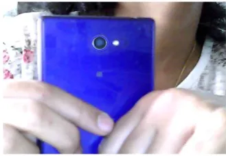
The Fig-3 shows the input image for the circular object detection. This is the reference input image which is used in order to detect the cameras having different radius ranges.
Fig- 3 Input image for the circular object detection
[image:3.595.311.558.62.242.2]Fig-4 shows the cameras having radius in the range between 10-19. In that, minimum and maximum radius range is given. Here, Minimum radius is 10 and Maximum radius is 19. So, the camera in the range of 10-19 is detected. The results obtained are given as follows:
Fig-4 cameras having radius(pixel difference) in range between 10-19
[image:3.595.39.285.237.409.2]Fig-5 shows the cameras having radius in the range between 15-30. In that, minimum and maximum radius range is given. Here, Minimum radius is 15 and Maximum radius is 30. So, the camera in the range of 15-30 is detected.
Fig-5 cameras having radius (pixel difference) in range between 15-30
[image:3.595.314.553.354.506.2]Fig-6 shows the cameras having radius in the range between 12-30. In that, minimum and maximum radius range is given. Here, Minimum radius is 12 and Maximum radius is 30. So, the camera within the range of 12-30 is detected.
Fig-6 cameras having radius (pixel difference) in range between 12-30
Fig- 7 shows the real time captured image from the web camera. The algorithm takes 200 frames continuously and it process two frames simultaneously. Here, the camera is detected by using the circular hough transform. The Fig-8 shows that the position of camera is detected and it is indicated by blue circle.
[image:3.595.41.282.509.674.2] [image:3.595.357.522.631.745.2]© 2018, IRJET | Impact Factor value: 6.171 | ISO 9001:2008 Certified Journal | Page 3664 The algorithm which is based on Retro-reflective
property uses retro-reflective property in order to detect the location of camera. Digital cameras are having the CCD sensors. The CCD sensors are having retro-reflective property. Retro-reflection causes light to reflect directly back to its source, independent of its incident angle. CCD sensors are mounted at the focal plane of the camera’s optical lens. CCD cameras have an optical property that when the light incident on camera then it produces well-defined light reflections. By tracking these retro-reflections we can detect and track cameras pointed at a given area.
Retro-reflection is returning light only within an extremely narrow-cone, with minimum scattering. The IR transmitter module which surrounds the lens of web camera, will continuously transmit the IR rays in the field of view. When these IR rays strikes on camera’s lens, a white circular speckle is seen in the image captured by the web camera. This white circular speckle can be seen due to the retro reflection. This circular speckle can be detected using algorithm in MATLAB.
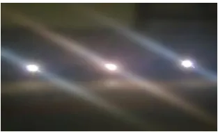
After locating white speckle, centroid is calculated later and axis position of the camera’s lens is calculated. The Fig-8 represents input image is captured by the camera. These three flashes are considered as an retro-reflections obtained by the corresponding three digital cameras.
Fig-8 Input image
The Fig-9 shows YCbCr format of the input image. The RGB image is converted into the YCbCr format. It’s luminance, chrominance blue and chrominance red part is separated.
Fig.9 YCbCr format image
[image:4.595.308.565.117.261.2]Fig-10 shows the binary part of the input image. The image is then converted in to binary image with the help of thresholding.
Fig-10 Binary image
In that, the area and the centroid is calculated so that it is given to the Raspberry Pi Board.
Table 1. Centroid and Area Calculation:
Sr. No. Area Centroid
X- axis coordinates
(pixels)
Y-axis coordinates
(pixels)
1 1431 152.54 456.95
2 976 526.33 447.48
[image:4.595.83.240.400.495.2]3 1284 886.81 427.40
Table-1 represents Centroid and Area Calculation of the obtained reflections. It gives X-axis co-ordinates and Y-axis co-ordinates of the obtained reflections. It is obtained by using the image processing algorithms. Fig-11 shows the RGB image in which camera position is detected.
Fig-11 RGB image in which camera position is detected
[image:4.595.318.546.538.660.2] [image:4.595.44.278.588.737.2]© 2018, IRJET | Impact Factor value: 6.171 | ISO 9001:2008 Certified Journal | Page 3665 Fig-12 Hardware Setup
[image:5.595.37.289.88.225.2]After installation of the different support packages such as support package for Raspberry Pi 3 Board, support package for Web Camera Raspberry Pi 3 Board is interfaced with the MATLAB by using Wi-Fi. Fig-12 shows the servomechanism which is used to neutralize the camera. In the servomechanism two servo motors are used. One servo motor is used for movement in the X-direction and another servo motor is used for movement in the Y-direction.
Fig-13 Distorted captured image
Fig-13 shows the captured image which is get distorted. As per the control signal obtained from the image processing algorithms Servomechanism will move towards the Camera’s lens direction and strong light source(LASER) is emitted on the camera lens so that the captured picture is get distorted.
VI.
CONCLUSION:
This system is used to detect the digital camera in the photography prohibited area. By using different image processing algorithms, position of camera lens is calculated. There are two image processing algorithms, first is based on the Circular Hough Transform and other is based on the Retro-Reflection method. The Raspberry Pi 3 board gives control signal to the Servomechanism. The Servomechanism operates according to control signal which are received from image processing algorithm(MATLAB). The strong light source is placed on the Servomechanism . Because of the strong light source is
focused on the camera , the user gets the distorted image. This system provides many applications such as for preventing piracy at the theaters, the places where maintaining secrecy is important such as in museums, temples, Shopping malls, jewelry stores etc.
REFERENCES
[1] Pravin Dhulekar, Swapnali Choudhari, Priyanka Aher, Yogita Khairnar, ”Arduino based Anti-Photography System for Anti-Photography Prohibited Areas” published in Journal of Science and Technology (JST) Volume 2, Issue 5, May 2017
[2]A.K. Veeraraghavan, S. Shreyas, Ramachandran, V. Kaviarasan, ”A Survey on Reduction of Movie Piracy using
Automated Infrared System” published in International Journal of Innovative Research in Computer and Communication Engineering, Vol. 5, Issue 11, November 2017.
[3] P.A. Dhulekar, Priyanka Aher, Yogita Khairnar, Swapnali Choudhari “Design of IR based Image Processing Technique for Digital Camera Deactivation” presented in IEEE International Conference on Global Trends in Signal Processing, Information Computing and Communication 2016.
[4] Kiran Kale, SushantPawar and PravinDhulekar, “Moving Object Tracking Using Optical Flow and Motion Vector Estimation” Published in IEEE 4th International conference on reliability, Infocom technologies and optimization (ICRITO 2015), 2-4 Sept 2015.
[5]J.Manasa, J.T.Pramod, Dr.S.A.K.Jilani, Mr.S. Javeed Hussain, ”Real Time Object Counting using Raspberry Pi”, International Journal of Advanced Research in Computer and Communication Engineering, Vol. 4, Issue 7, July 2015.
[6] Virendra Kumar Yadav, Saumya Batham, Anuja Kumar Acharya,"Approach to accurate circle detection: Circular Hough Transform and Local Maxima concept", Published in Electronics and Communication Systems (ICECS), 2014 ,International Conference on 13-14 Feb. 2014
[7]Snehasis Mukherjee, Dipti Prasad Mukherjee, “Tracking Multiple Circular Objects in Video Using Helmholtz Principle”, Published in: Advances in Pattern Recognition, 2009. ICAPR '09. Seventh International Conference on ,4-6 Feb. 2009 .
[image:5.595.116.207.358.519.2]