International Journal of Emerging Technology and Advanced Engineering
Website: www.ijetae.com (ISSN 2250-2459, ISO 9001:2008 Certified Journal, Volume 6, Issue 5, May 2016)
336
Design and Implementation of an Intelligent Security System
Using Microcontroller and GSM
Chiranjit Hati
1, Abhirup Chatterjee
2, Ahamed Dewan
3, Subhayan Bera
4, Biswarup Mukherjee
5, Aniruddha Ghosal
61
Wipro Ltd. Kolkata,West Bengal
2Infosys Tech. Ltd. Bhubaneswar, Odisha 3ERTL(E) STQC,West Bengal 4
Infosys Tech. Ltd., Hyderabad, Telangana
5Dept. of ECE, NITMAS, West Bengal 6IRPEL, CU, Kolkata, West Bengal
Abstract— Security is a prime and common issue in our day to day life. This paper deals with providing household password protected security which informs the user or rather alerts them when somebody tries to break their security. When the owner secures properties with this INTELLIGENT SECURITY SYSTEM then owner is always confirmed that if somebody tries to crack the unique key then after every 3(three) attempts the system will be disabled and send a SMS (Short Message Service) to the predefined owner. The security system consists of a microcontroller P89V51RD2 (8-bit, 64K Flash memory, 1K RAM), LCD (16X2), Push Button Switch (Active Low), Motor, Buzzer, GSM Module. Microcontroller is the key component of the entire system and the other components are interfaced with the microcontroller using some driver programs. The main program is stored in the Flash memory (64K).
Keywords—digital lock; GSM module; microcontroller.
I. INTRODUCTION
Security is a prime concern in our day-today life. Need of security is increasing daily. Everyone wants to be as much secure as possible. For the house protection, we must use a good securing technique which may permit us to lead a stress free life concerning the security of our property and this will be possible if we obtain the proper lock that is organized regarding many disengaging options of a securing process. For example when we go to office or leave our house for several days we have to secure our house. So, we have to design such a system which can secure our house or if anyone tries to unlock our system then we must have to be alerted. Not only for house but also it can be used in office also. From past time security has been developing day by day [1]-[3].
A digital (or electronic lock) is a locking device which operates by means of electric current. Electric locks are sometimes stand-alone with an electronic control assembly mounted directly to the lock. More often electric locks are connected to an access control system.
The most basic type of electronic lock is a magnetic lock (commonly called a mag lock) [4]. A large electro-magnet is mounted on the door frame and a corresponding armature is mounted on the door. When the magnet is powered and the door is closed, the armature is held fast to the magnet. Mag locks are simple to install and are very attack resistant. One drawback is that improperly installed or maintained mag locks can fall on people and also that one must unlock the mag lock to both enter and leave. This has caused fire marshals to impose strict codes on the use of mag locks and the access control practice in general.
As time passes, digital lock using microcontroller was invented [5]. Use of microcontroller program, makes high end security. It is not very easy to know the password combination in microcontroller based security system until anyone tries to unlock the door for indefinite times. So, a system must be implemented which sends us information about the intruder‟s activity. So, a module is connected with the microcontroller which will send the information to the owner and by getting information owner can take steps.
II. BRIEF OVERVIEW
In the past time digital locks were formed by flip-flops and relay coil had been used. But there was not so much security using that. Because anyone could easily knows about the combination and unlock the door which is not desired at all. Nowadays different types of digital locking system have invented. Some of they are;
A. Numerical codes, passwords, and passphrases
International Journal of Emerging Technology and Advanced Engineering
Website: www.ijetae.com (ISSN 2250-2459, ISO 9001:2008 Certified Journal, Volume 6, Issue 5, May 2016)
337
B. Security tokens
Another means of authenticating users is to require them to scan or "swipe" a security token such as a smart card or similar, or to interact a token with the lock. For example, some locks can access stored credentials on a personal digital assistant (PDA) using infrared data transfer methods.
C. Biometrics
As biometrics become more and more prominent as a recognized means of positive identification, their use in security systems increases. Some new electronic locks take advantage of technologies such as fingerprint scanning, retinal scanning and iris scanning, and voiceprint identification to authenticate users.
D. RFID
Radio-frequency identification (RFID) is the use of an object (typically referred to as an RFID tag) applied to or incorporated into a product, animal, or person for the purpose of identification and tracking using radio waves. Some tags can be read from several meters away and beyond the line of sight of the reader. This technology is also used in modern electronic locks. [6].
In digital system intelligence is used to mean that a system which can work automatically in the absence of mankind. An intelligent digital lock system automatically detects the activity of the user who wants to unlock the door. Not only it can detect user information but it can also take decision to secure the system. It can send the information about the user to the owner.
Different types of features are added in the intelligent security system to get better security. In some intelligent system video camera is installed to detect the face of the person. Controller checks whether the persons is the user or the owner and controller sends the information to the owner to become alert. In some intelligent system a buzzer is connected with the microcontroller. So, if the user enters wrong password consecutively then the buzzer will ring. Some intelligent system uses a process in which the system does not work after consecutive entering of passwords.
The proposed Intelligent Security System consists of a digital door lock which contains a microcontroller. A GSM modem is added with the microcontroller in this system. When someone enters three wrong passwords consecutively, microcontroller sends commands to the GSM modem through TX pin. One SIM card is inserted in the GSM module. After sensing the commands GSM modem sends a security alert SMS text to the MSISDN number specified in the commands.
There is another feature which is added. After entering three consecutive wrong passwords the LCD will display “System Error” and wait for predetermined time period (say 15 minutes). In that time microcontroller would not take any input from the user. So, this process also helps to make more secure system.
III. IMPLEMENTATION
The main objective of Intelligent Security System is that it should provide security and safety features for a home by digital lock combination along with SMS alert facility. To implement the intelligent security system various tasks are followed in a controlled manner.
A. Making of blueprint
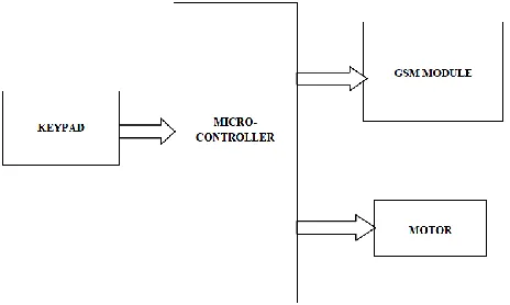
First blueprint of the system is made which is to be implemented. The blueprint represents the problem formulation, the block diagram & accordingly the technical details for the project requirements. Fig. 1 shows the basic block diagram of the intelligent security system. It consists of a microcontroller along with keyboard interface to input the password. The output signals are driving the motor, LCD display and the GSM module to either open/close the door or to send the security code.
B. Choice of microcontroller and other components
[image:2.612.329.561.531.670.2]To control the system a controller system must be needed. So, suitable microcontroller is opted which controls the whole system. After choosing the controller all the other components which are required to design the whole system are collected and all the components are interfaced with the controller. The components are listed in table 1.
International Journal of Emerging Technology and Advanced Engineering
Website: www.ijetae.com (ISSN 2250-2459, ISO 9001:2008 Certified Journal, Volume 6, Issue 5, May 2016)
338
TABLEI
LIST OF COMPONENTS
Component s
Details
Specification Key features
Microcontro
ller P89v51RD2
•80C51 Central Processing Unit •5 V Operating voltage from 0 to 40 MHz
•64 kB of on-chip Flash program memory with ISP and IAP •Supports 12-clock (default) or 6-clock mode selection via software or ISP
•SPI (Serial Peripheral Interface) and enhanced UART
•PCA (Programmable Counter Array) with PWM and Capture/Compare functions •Four 8-bit I/O ports
Display & keyboard 16X2 LCD Display and matrix keyboard
•LCDs are economical •Easily programmable • No limitation of displaying special & even custom characters • 5x7 pixel matrix
GSM Module Tarang GSM-900 Band Working Frequency-900/1800/1900 MHZ. Noise: <-79dBm. Transmission Power: 33dBm +/-2dBm. Receiving Sensitivity: -102 dBm.
Working Temperature -30C to 80C
Storage Temperature -35C to 85C Transmitting Current <=2A (peak) Receiving Current <=80mA (peak) Interface RS-232
DC Motor & Driver
12v motor & L239D
A A enable
B enable
Description
0 0 stops or breaks
0 1 runs
anticlockwise
1 0 runs clockwise
1 1 stops or breaks
C. Programming the controller and interfacing
The most important thing of the project is the generation of password. So first the flow chart of the program is designed as below in fig. 2.
Then the program of digital lock is written on controller. To enter the password switches are needed. Once the correct password is entered it is also needed to control the motor which will operate the door. Now, The various operations which are performed they must be displayed. So, a LCD is to be interface to display the various operations and its result.
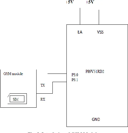
D. Interfacing of GSM module
Now, a SMS must be sent to the owner if wrong passwords are entered consecutively. So, GSM module is used to send the SMS. This project presents a way to interface GSM Module with microcontroller P89V51RD2 without making use of computer to send AT commands to the module. Instead of using HyperTerminal or any other PC interface, the controller itself sends a fixed AT command to the GSM module. The information response and result codes are received and displayed on a 16x2 LCD.
International Journal of Emerging Technology and Advanced Engineering
Website: www.ijetae.com (ISSN 2250-2459, ISO 9001:2008 Certified Journal, Volume 6, Issue 5, May 2016)
[image:4.612.340.550.145.363.2]339 Fig. 2. Program flow chart
Fig. 3. Interfacing of GSM Module
IV. HARDWARE REALIZATION
To start programming the CoRe51 Board first a compiler is needed which translates the higher level c code to the hex code which can be recognized by the microcontroller (microcontroller only understands hex code). Here „Keil μVision‟ compiler has been used for compiling the program. Then a burner is needed which will transfer the hex code generated from the computer to the microcontroller program memory. Here Flash Magic has been used as a burner.
After downloading the program the functionality of the system are tested. The following figures show the system functionality.
• Waiting for password:
[image:4.612.60.287.152.685.2]International Journal of Emerging Technology and Advanced Engineering
Website: www.ijetae.com (ISSN 2250-2459, ISO 9001:2008 Certified Journal, Volume 6, Issue 5, May 2016)
[image:5.612.52.290.133.270.2]340 Fig. 3. System displays “Enter Password” to get the password
• Entering the password:
[image:5.612.325.562.159.331.2]When the user is entering the password the system will show the password on the display. In this case the password is four digits long and the value is 1234.
Fig. 4. System displays the entered password
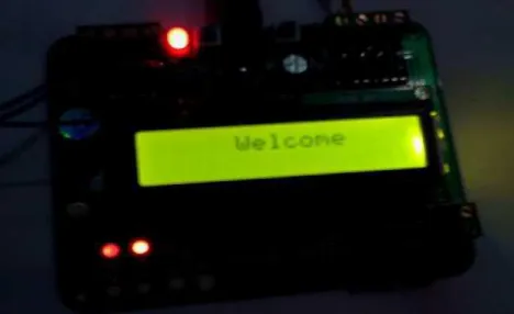
• Welcome note after verification:
The system displays “Welcome” if the password is correctly entered and correspondingly motor will run to open the door.
Fig. 5. System displays “Welcome” for correct password
• Indicating wrong password:
[image:5.612.51.287.346.492.2]The system will display “Wrong Password” if the entered password is incorrect.
Fig. 6. System displays “Wrong Password” for incorrect password
• For unauthorized use of system:
For three consecutive incorrect passwords the system halts for fifteen minutes and GSM module sends an alert message
Fig. 7. System displays “System Error” for three incorrect passwords
V. CONCLUSION
This system works like an intelligent door lock system and this can secure our house, office etc. The performance can be improved by using special characters in password. By using EEPROM dynamic memory the password can be reset by the owner.
REFERENCES
[image:5.612.326.560.405.536.2] [image:5.612.51.285.563.706.2]International Journal of Emerging Technology and Advanced Engineering
Website: www.ijetae.com (ISSN 2250-2459, ISO 9001:2008 Certified Journal, Volume 6, Issue 5, May 2016)
341
[2] Jun Zhang, Hui Wang, TianhuaMeng and Guangming Song, 2011,“Design of a Wireless Sensor Network Based Monitoring System for Home Automation”, International Conference on Future Computer Sciences and Application (ICFCSA), pp. 57-60, Nanjing, June 2011.
[3] K.K. Griffiths and R. Melanie,2012, "Smart Home Security", Homebuilding & Renovating. Retrieved University of Leeds [4] Geringer A. Geringer R. Geringer D. Electromagnetic Door Lock
Device, U.S. Patent 4,826,223, May 2, 1989
[5] Nikhil Agarwal,G.Subramanya Nayak, "Microcontroller based Home Security System with Remote Monitoring"International Conference on Electronic Design and Signal Processing (ICEDSP) 2012