Abstract – Universal Stretch and Bending Machine (USBM) is a
combination of Stretch Machine and Bending Machine which are used in car door sash production. The main purpose of combining these two machines is to reduce the number of machines, space utilization and increase productivity. This paper basically focuses on the design and modeling for revolute control of USBM simplified model. Basically, comparative evaluation of intelligent control (Fuzzy Logic Controller) systems that suites the USBM simplified model are evaluated. The evaluation is done by comparing the PD–type FLC performance of different fuzzy rules and membership functions in terms of time response and integral square error. Prior to that, mathematical model of the system is first derived and verified by SIMULINK (MATLAB). Based on the simulation result, PD-type FLC with 5 membership function is better than PD-type FLC with 7 membership function in terms of time response specifications and integral square error.
Key-words: Universal Stretch Bending Machine, PD-type Fuzzy Logic Controller, Servomotor.
I. INTRODUCTION
In recent car door sash production requires for both stretch and bending machines. In minimizing the usage of two machines and by combining them into a single machine but with two functions as before, this could lead to space utilization and increase productivity. The Universal Stretch and Bending Machine comprises of prismatic and revolute movements. The studies for these movements are conducted individually on the simplified model for choosing the controller that best suites the design requirement before it can be implemented on the prototype machine. In recent years, the CNC controller [1]-[2] is still used in controlling machine and much more can be explored to improve its performance.
The objective of this paper is to study and compare the PD-type FLC performance of different fuzzy rules and membership functions on revolute control of USBM simplified model in terms of its time response specifications and integral square error.
Designing the Fuzzy Logic Controller, on the other hand, does not require for prior knowledge on system characteristic equation. The so called intelligent controller function is much closer in spirit to human thinking and natural language than traditional logical system where it provides a means of converting a linguistic control strategy
Reza Ezuan Samin is with Universiti Malaysia Pahang, Kuantan, Malaysia. He can be reached at [email protected]
Mohd Syakirin Ramli is with Universiti Malaysia Pahang, Kuantan, Malaysia. He can be reached at [email protected]
Mohd Ashraf Ahmad is with Universiti Malaysia Pahang, Kuantan, Malaysia. He can be reached at [email protected]
based on expert knowledge into an automatic control strategy [3]. The implementation of Fuzzy Logic Controller in [4] using microcontroller proves the robustness of this controller where the results for both simulation and experimental are identical with regard to the load mass change.
II. REVOLUTE MODEL
The revolute model for the USBM was adapted from the model of the DC servomotor. DC servomotor is chosen since it is easier to control where by changing the armature voltage or current, the position or the speed of the DC servomotor can be varied. Fig.1 below shows the schematic of the armature controlled DC servomotor with a fixed field circuit. For transfer function derivation, this system was divided into three major components of equation, which are electrical equation, mechanical equation, and electro-mechanical equation [5].
Fig.1. Schematic of DC servomotor system
The electrical equation for DC servomotor system could simply be obtained based on the Kirchoffs Voltage Law as follows:
) ( )
( )
( v t
dt di L t i R t
ea = a a + a a + b (1)
or in frequency domain
) ( ) ( )
(s R sL I V s
Ea = a+ a+ b (2) where ea and ia are the armature voltage and current respectively, Rais the armature resistance, and La is the armature inductance. The back emf,vb, on the other hand, induced by the angular speed of the motor shaft, such that
) ( )
( )
(s k s k s s
Vb = bωm = b θm (3)
where kbis the back-emf constant, ωm is the angular speed, and θm is the angular displacement.
Next, the mechanical equation can be obtained as follows:
dt d D dt d J
t m m m m
m
θ θ
τ ()= 22 + (4)
or in frequency domain
Performance Comparison of PD-type Fuzzy
Logic Controller of USBM Simplified Model
Reza Ezuan Samin, Mohd Syakirin Ramli and Mohd Ashraf Ahmad
The 5th Student Conference on Research and Development –SCO
11-12 December 2007, Malaysia
) ( ) (
)
(s s2J sD s
m m
m θ
τ = + (5)
where τm is the equivalent torque produced by the servomotor shaft, with Jm and Dm as the equivalent inertia and equivalent viscous density by the DC servomotor respectively.
The electromechanical equation of the DC servomotor was related with the equivalent torque produced by the motor shaft is basically proportional to the multiplication of armature current with a motor torque constant, or
Ia kt m =
τ (6)
From (1) to (6), the frequency domain open loop block diagram for the schematic in Fig. 1 is obtained and shown as in Fig. 2.
Fig.2. Frequency domain block-diagram representation of DC servomotor system.
Therefore, based on the block diagram in Fig.2, the open loop transfer function for a third order armature controlled DC servomotor system is given as follows:
(
)
⎟⎟ ⎠ ⎞ ⎜⎜ ⎝ ⎛ + + + + ⎟⎟ ⎠ ⎞ ⎜⎜ ⎝ ⎛ = m a b t a m m a a m a m a t a m J L k k R D J L L D R s s s J L k s E s 2 ) ( ) (θ (7)
III. MODELLING IN STATE SPACE
From the block diagram in Fig.2, the state variables for the third order system of DC servomotor can be defined as,x1(t)=ia(t)≡armature current, x2(t)=θm(t)≡angular displacement of the motor shaft, and
≡ = dt t d t
x3() m() θ
angular velocity of the motor shaft.
Meanwhile, the state input and state output for this system are defined as, u(t)=ea(t)≡input signal into the system, and y(t)=x2(t)≡output signal from the system, respectively.
In order to obtain the state-space representation of DC servomotor in space matrix, (1) is rearranged and substituted with state variables
x
1,x
2, andx
3such that) ( 1 ) ( ) ( )
( 1 3
1 e t
L t x k k t x L R t x a a t b a
a − +
− = • (8) Let ) ( ) ( ) ( )
( 2 3
2 x t
dt t d dt t dx t
x = = m =
• θ (9) Now, let 2 2 3
3( ) ( ) dt d dt t dx t
x• = =
θ
m (10)By substituting (4) into (6), it could be obtained that
) ( )
( )
( 1 3
3 x t
J D t x J k t x m m m t − = • (11)
Therefore, the state-space representation of DC servomotor in space matrix could be expressed in this form:
⎥ ⎥ ⎥ ⎥ ⎥ ⎦ ⎤ ⎢ ⎢ ⎢ ⎢ ⎢ ⎣ ⎡ • • • ) ( ) ( ) ( 3 2 1 t x t x t x = ⎥ ⎥ ⎥ ⎦ ⎤ ⎢ ⎢ ⎢ ⎣ ⎡ ⎥ ⎥ ⎥ ⎥ ⎥ ⎦ ⎤ ⎢ ⎢ ⎢ ⎢ ⎢ ⎣ ⎡ − − − ) ( ) ( ) ( 0 1 0 0 0 3 2 1 t x t x t x J D J k L k L R m m m t a b a a + ( ) 0 0 1 t e L a a ⎥ ⎥ ⎥ ⎥ ⎥ ⎦ ⎤ ⎢ ⎢ ⎢ ⎢ ⎢ ⎣ ⎡ (12) and
[
]
⎥ ⎥ ⎥ ⎦ ⎤ ⎢ ⎢ ⎢ ⎣ ⎡ = ) ( ) ( ) ( . 0 1 0 ) ( 3 2 1 t x t x t x ty (13)
IV.FUZZYLOGICCONTROLLER
Fuzzy Logic Controller has emerged as one of the most active and fruitful research areas in the application of fuzzy set theory, fuzzy logic and fuzzy reasoning. In contrast to conventional control techniques, fuzzy logic control is best utilized in complex ill-defined processes that can be controlled by a skilled human operator e.g. complex chemical plant without much knowledge of their underlying dynamics [3]. Generally, Fuzzy Logic Controller comprises of four principal components [6]:
• fuzzifier • knowledge base • inference engine • defuzzifier
The component of the Fuzzy Logic Controller can be clearly seen based in Fig.3 below:
Fig.3. Fuzzy Logic Controller components.
TABLE 1. Input and output of fuzzy variables
No Input Output
1 Error voltage between the actual and desired angular position. (e)
Control action to the system plant (Δu)
2 The change of error voltage between the actual and desired angular position. (Δe)
A PD-type fuzzy logic controller utilizing angular position error and derivative of angular position error is developed to control the DC motor system. The hybrid fuzzy control system proposed in this work is shown in Fig. 4, where r(s) and
θ
(s) are the desired angle and angular position of the DC motor, whereas k1, k2 and k3 are scalingfactors for two inputs and one output of the fuzzy logic controller used with the normalised universe of discourse for the fuzzy membership functions.
Fig.4. PD-type FLC control structure
In this paper, triangular membership functions are chosen for angular position error, derivative of angular position error, and control voltage with 50% overlap. Normalized universes of discourse are used for both angular position error and its derivative and control voltage. Scaling factors k1 and k2 are chosen in such a way as to convert the
two inputs within the universe of discourse and activate the rule base effectively, whereas k3 is selected such that it
activates the system to generate the desired output. Initially all these scaling factors are chosen based on trial and error. To construct a rule base, the angle error, angle error derivative, and torque input are partitioned into five and seven primary fuzzy sets for five and seven membership functions respectively as shown below
Angle error (e) = {NM NS ZE PS PM}
= {NB NM NS ZE PS PM PB} Angle error derivative (Δe) = {NM NS ZE PS PM}
= {NB NM NS ZE PS PM PB} Torque (Δu) = {NM NS ZE PS PM}
= {NB NM NS ZE PS PM PB}
where
NM = Negative Medium, NS = Negative Small, ZE = Zero,
[image:3.612.321.534.238.699.2]PS = Positive Small, PM = Positive Medium
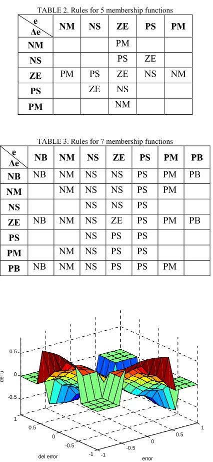
Table 2 and 3 show the rules for five and seven membership functions respectively. It is noted that, 11 rules is needed to compute the rules for five membership functions while 35 rules is required for seven membership functions. In this study, the conditions of error (e), the rate
of change of error (Δe) and the output which is the change in the control signal (Δu) are formulated based on the underdamped system response behaviour. The control surface for both types of membership functions is shown in Fig. 5 and 6. Next, max-min composition technique is used as the fuzzy inference method [4]. Centroid defuzzification technique is used for defuzzification process as this method is the most prevalent and physically appealing of all defuzzification methods.
The three scaling factors, k1, k2 and k3 for both type of
membership functions were chosen heuristically to achieve a satisfactory set of time domain parameters. For five membership functions these values were recorded as, k1 =
0.2 k2 = 0.012 and k3 = -10 while for seven membership
functions these values were recorded as, k1 = 0.22 k2 = 0.05
[image:3.612.75.300.257.332.2]and k3 = 3.4.
TABLE 2. Rules for 5 membership functions e
Δe NM NS ZE PS PM
NM PM
NS PS ZE
ZE PM PS ZE NS NM
PS ZE NS
PM NM
TABLE 3. Rules for 7 membership functions e
Δe NB NM NS ZE PS PM PB
NB NB NM NS NS PS PM PB
NM NM NS NS PS PM
NS NS NS PS
ZE NB NM NS ZE PS PM PB
PS NS PS PS
PM NM NS PS PS
PB NB NM NS PS PS PM
-1 -0.5
0 0.5
1
-1 -0.5 0 0.5 1 -0.5 0 0.5
error del error
de
l u
[image:3.612.322.525.535.694.2]-1 -0.5
0 0.5
1
-1 -0.5 0 0.5 1 -0.5 0 0.5
error del error
de
[image:4.612.79.284.56.208.2]l u
Fig.6. Surface PD-type FLC with 7 MFs. V. SIMULATION RESULTS
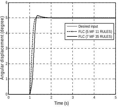
Fig. 7 shows the angular displacement response of DC servomotor using PD-type FLC with 5 MFs and 7 MFs. It is noted that both controllers can track the step input response of 5 degree. However, PD-type FLC with 5 MFs shows a better performance in terms of time response specifications and integral square error as compared to the PD-type FLC with 7 MFs controller. For the time response performance, the PD-type FLC with 5 MFs produce settling time and rise time of 0.247 s and 0.156 s respectively whereas the PD-type FLC with 7 MFs produce settling time and rise time of 0.298 s and 0.184 s respectively. It shows that the PD-type FLC with 35 rules and 7 MFs results in a slower response as compared to PD-type FLC with 11 rules and 5 MFs. It can be said that with higher number of rules the complexity to compute the rules will increase and affect the speed of the response. In term of integral square error, the PD-type FLC with 5 MFs results in twice less of ISE as compared to the PD-type FLC with 7 MFs with the value of 1.755 and 3.515 respectively. The comparative assessment of both controllers is summarized in Table 4.
0 1 2 3 4 5
0 1 2 3 4 5 6
Time (s)
A
ngul
ar
di
s
pl
ac
em
ent
(
degr
ee)
[image:4.612.322.522.230.395.2]Desired input FLC (5 MF 11 RULES) FLC (7 MF 35 RULES)
Fig.7. Simulated response of the angular displacement. Fig. 8 shows the angular velocity response of DC servomotor using PD-type FLC with 5 MFs and 7 MFs controller. It is noted that the PD-type FLC with 5 MFs controller produce maximum angular velocity of 33 deg/sec
and settle down at 1.247 sec whereas the PD-type FLC with 7 MFs controller produce maximum angular velocity of 26.5 deg/sec and settle down at 1.298 sec. It is proven that the PD-type FLC with 5 MFs controller result in faster settling time with maximum angular velocity as compared to PD-type FLC with 7 MFs controller. The angular velocity response also proved that both PD-type FLC controller required high velocity consumption at the transition state in order to achieve the desired input level and this will be very effective for high speed operation of DC motor. In this study, the implementation of PD-type FLC required a large amount of design effort in order to determine the best scaling parameters, k1, k2 and k3 respectively. Note that a
properly tuned scaling parameters, k1, k2 and k3 in PD-type
FLC could produce better results.
0 1 2 3 4 5
-5 0 5 10 15 20 25 30 35
Time (s)
A
n
g
u
la
r v
e
lc
oit
y
(
deg
re
e/
s
e
c
)
FLC (5 MF 11 RULES) FLC (7 MF 35 RULES)
[image:4.612.311.549.450.558.2]Fig.8. Simulated response of the angular velocity.
TABLE 4. Performance comparison of angular displacement.
Controller Settling time (s)
Rise Time (s)
Overshoot (%)
ISE
PD-type FLC with
5 MFs 0.247 0.156 0.12 1.755
PD-type FLC with
7 MFs 0.298 0.184 2.86 3.515
VI.CONCLUSION
[image:4.612.87.283.498.676.2]VII.ACKNOWLEDGEMENT
This work was supported by Faculty of Electrical & Electronics Engineering, Universiti Malaysia Pahang, especially Control & Instrumentation (COINS) Research Group.
VIII.REFERENCES
[1] D. Hanafi, M.Tordon and J. Katupitiya, “An Active Axis Control System for a Conventional CNC Machine”, Proceeding of the 2003 IEEE/ASME, International Conference on Advanced Intelligent
Mechatronics, pp.1188-1193, 2003
[2] J. Fortgang, W.Singhose, J. Marquez and J.Perez, “Command Shaping for Micro-Mills and CNC Controllers”, 2005 American Control
Conference, pp.4531-4536, 2005
[3] Lee, C.C., “Fuzzy Logic in Control System: Fuzzy Logic Controller - Part I and Part II”, IEEE Transactions on SMC, 20, pp.404-435, 1990. [4] Hoang Le-Huy and Maher Hamdi, “Control of Direct Drive DC
Motor by Fuzzy Logic”, IEEE Transactions, pp. 732-738, 1993 [5] N.S.Nise, Control System Engineering, John Wiley & Sons, 4th
Edition, pp. 764-767, 2004
[6] Mamdani, E.H., Efstathiou, H.J., and Sugiyama, K., “Developments in Fuzzy Logic Controller”, Proc. of the 23rd IEEE Conference on Decision and Control, pp. 888-893, 1984.
IX. BIOGRAPHIES
Reza Ezuan Samin received his Bachelor of Electronics Engineering (Hons) in 2004 and Masters in Electrical Engineering (Hons) majoring in Mechatronics in 2007 from Universiti Sains Malaysia and Universiti Tun Hussein Onn Malaysia respectively. His publication mainly focused on control and artificial intelligence. His research interest includes object recognition, control and application using artificial intelligence. He is also a member of BEM.
Mohd Syakirin Ramli received his Bachelor of Science in Electrical Engineering in 2005 from Purdue University (USA), and Master of Engineering – Mechatronics & Automatic Control from Universiti Teknologi Malaysia in 2007, His research interest focusing on system identification, adaptive & intelligent control system. He is also a member of BEM.