2020 4th International Conference on Modelling, Simulation and Applied Mathematics (MSAM 2020) ISBN: 978-1-60595-674-9
Research on Vector Control Simulation Based on Field-Road Coupling
Xu-xuan CHEN
1,2and Zhou ZENG
11
School of Information Science and Engineering
Wuhan University of Science and Technology Wuhan 430081 China
2
School of Power and Mechanical Engineering Wuhan University Wuhan 430072 China
Keywords: Permanent magnet synchronous motor, Field-circuit coupling, Vector control, Co-simulation.
Abstract. In vector control simulation, the MATLAB/Simulink model of the permanent magnet synchronous motor cannot fully simulate the inherent characteristics of the motor. It leads to problems such as reduced simulation accuracy and limited applicability of analysis results. In order to solve these problems, this paper designs a joint simulation model. This model is established based on the direct field-circuit coupling equation and the vector control strategy. It can take into account both the analysis of the electromagnetic characteristics of the motor and the analysis of the control circuit. This paper analyzes the speed, current and electromagnetic field distribution under different working conditions, and these simulation results show that the model is feasible.
Introduction
As the core component of electric car, the motor drive system mainly functions are energy conversion and power output [1]. A suitable motor drive system can not only provide sufficient torque output but also has excellent speed regulation performance. A vector control system composed of a permanent magnet synchronous motor (Permanent Magnet Synchronous Machine (hereinafter referred to as PMSM) and vector control can not only take advantage of the high power density, high precision and high efficiency of PMSM, but also improve the speed and flexibility of the drive system The performance is in line with the requirements of electric car for electric drive systems [2].
During the design and debugging of PMSM vector control system, it is necessary to simulate it practically and accurately. At present, many scholars have done a lot of work on vector control simulation. Reference [3] designed a parameter adaptive PMSM vector control system based on fuzzy control theory. Reference [4] optimized SVPWM link in vector control. Reference [5] proposed a vector control simulation model without position sensor based on the MRAS principle. These simulation models were established based on mathematical models of various components, which can realize precise modeling of control principles and control algorithms [6]. However, due to the inherent characteristics of the motor (electromagnetic distribution, magnetic pole shape, cogging effect, etc.), this MATLAB/Simulink model based on circuit simulation cannot completely simulate the actual operating conditions, which makes this model simulation analysis accuracy is reduced, and the applicable range is limited [7].
In view of the shortcomings of the above simulation models, this paper established a joint simulation model of PMSM vector control based on the field-circuit direct coupling method [8]. This model takes small PMSM as the research object. First, we built an electromagnetic model of the motor by the finite element analysis software, and established corresponding vector control circuit by Simulink. Then, the interface model of joint simulation is designed based on the solving equation of field-circuit direct coupling. Finally, in order to check the rationality and feasibility of the entire system, this paper analyzes two different operating conditions.
Section IV some data and graphics are analyzes and the model is proven logical. Conclusions are drawn in Section V.
Field-Circuit Coupling Method and Solving Equation
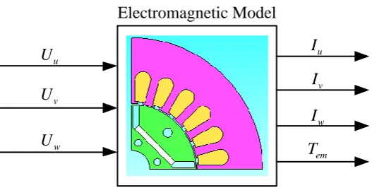
The coupling method uses direct coupling. The finite element model of the motor receives the voltage signal generated by the external control circuit model. Output signals can be obtained by solving the magnetic field equation and the voltage balance equation. The coupling method is shown in Figure 1.
Electromagnetic Model
u
U
v
U
w
U
u
I
v
I
w
I
em
[image:2.595.166.430.194.327.2]T
Figure 1. Direct field-coupling method.
The phase voltage output by the control circuit is Um, the armature phase current is im, the
equivalent resistance is Rm, and the leakage inductance of each phase is Lm, For a star-connected
PMSM, the voltage balance equation can be described in
.
m m m m m m
di
U R i L e
dt
(1)
Using the induced electromotive force em as an intermediate variable, Simultaneous voltage balance equation and finite element expression of induced electromotive force, by the way, the matrix expression of the voltage balance equation can be obtained
{ }U 2pL Cef[ ]T A [ ]{ } [ ]R I L A .
(2)
In this equation, { }U is the phase voltage vector, p is the number of pole pairs of the motor, Lef is
the armature length, [ ]C T is the matrix coefficient which was decided by the finite element division
method,
A is the derivative of magnetic potential vector [ ]A with respect to time.
For the motor model, the Maxwell equations are discretized by the weighted margin method, combined with the electromagnetic field finite element analysis method, and the first-order linear triangle is used as the division unit. its discrete matrix epression can be given
[ ]{ } [ ]K A T A [ ]{ }.C I
(3)
Simultaneous equations (2) and (3) can solve magnetic potential vector [ ]A and current [ ]I . Combining the value by the above equation with the mechanical motion equation of the stator can solve the motor speed and mechanical angle. The equation of mechanical motion is as follows
.
em L
d
T T J D
dt
Simulation Model Design
[image:3.595.101.497.174.325.2]The design of the field-circuit coupling model can be divided into three parts: control model design, interface model design, and finite element model design. Some parameters of the prototype are shown in Table 1.
Table 1. Prototype Parameters.
Parameter name Property
Parameter value Symbol Unit
Number of pole pairs 2 - -
Number of slots 24 - -
Rated voltage 288 U (V)
Rated speed 1800 n (rad·min-1)
Rated current 2.5 I (A)
Stator phase resistance 3.3 R (Ω)
Moment of inertia 3.610-4 J (kg·m2)
Control Model Design
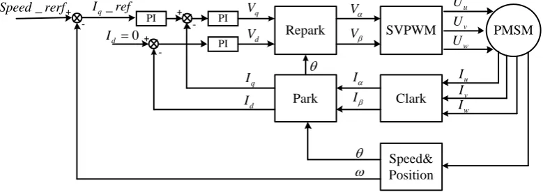
This paper uses Id 0 vector control strategy. The entire control model uses a double closed-loop PI control structure, the feedback signal is the real-time speed of the motor and the dual-axis current. The system obtains the reference voltage signal of the d-q axis by the PI controller of the inner current loop and the outer speed loop. The voltage signal is used as the input signal of the SVPWM link to control the drive signal of the inverter. The DC voltage source outputs a three-phase voltage which is correspond the speed of real-time, and then this voltage is fed to motor. Thecontrol block diagram is shown in Figure 2.
PMSM
PI
PI PI
_
Speed rerf Iq_ref
0 d I q V d V V V u U v U w U u I v I w I I I q I d I -+ + -+ Repark Park Clark SVPWM Speed& Position
-Figure 2. Motor control block diagram.
The key to implementing the above control simulation lies in the selection of PI control parameters and the implementation of the SVPWM algorithm. The former ensures the correct voltage reference voltage value and the latter determines the accurate IGBT drive signal. For the tuning of PI parameters, the commonly used method is the debugging method, that is, to obtain stable operating results by repeatedly debugging the parameters. This paper refers to the method of parameter adjustment of the vector control system described in Reference [9]. As for SVPWM link, this paper uses traditional seven-segment pulse modulation [10].
Finite Element Model
[image:3.595.89.479.475.613.2](1) Draw the geometric model of the motor, divide the fixed rotor area and define the boundary conditions.
(2) Import the finite element parameters of the internal coil. Connect the necessary measuring probes.
(3) Set the motor rotation mode to be driven by the mechanical angle change of the external circuit, and establish the input and output of the electromagnetic model.
Interface Model
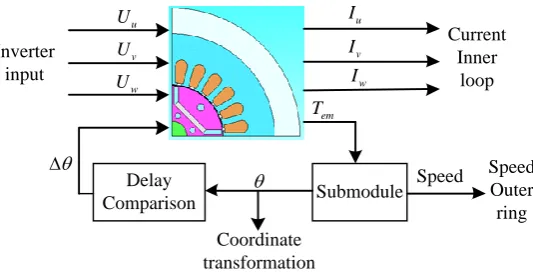
According to the solving equation and the coupling method, the finite element model needs to accept input voltage from an external control circuit, and it will output electromagnetic torque and current.
Define the three input ports of the interface model according to the above requirements, they are
u
U , Uv , Uw. Define four output ports, they are Iu, Iv, Iv and Te. The three-phase current signal is connected to the internal current loop as the feedback signal of the current inner loop after the coordinate transformation module. Because the motor speed is controlled by an external circuit, the driving signal in the finite element model needs to be an external driving signal. In this paper, the change amount of the position angle between adjacent sampling times is selected as the driving signal of the motor. The interface design is shown in Figure 3.
Current Inner
loop
Speed Outer ring Coordinate
transformation
Submodule Delay
Comparison Inverter
input
u
U
v
U
w
U
u
I
v
I
w
I
em
T
[image:4.595.163.430.324.462.2]Speed
Figure 3. Interface model design.
The submodule in the figure is used to output the position angle and speed. It was built based on the mechanical motion equation of the rotor.
Simulation Results and Analysis
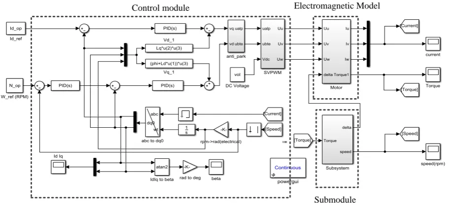
Co-simulation Model
Submodule Electromagnetic Model Control module
Figure 4. Joint simulation platform.
Results and Analysis
Set the motor reference speed to 1800r / min, add a load of 5N m at 0.6s, and the total running time is 1.5s. The change of the motor speed and d-q axis current are shown in Figure 5.
Id
Iq
Figure 5. Speed change and d-q axis current change.
Before the load is applied, the speed of the motor changes drastically in the time period of 0.05s. then acceleration gradually stabilized, overall speed rises steadily. This system speed adjustment process takes 0.5s, it reaches 95% of the expected speed at 0.3s and there is no overshoot in the entire speed-up process. This shows that the entire system has great accuracy and good rapidity. For the current of q axis, it has the same trend as speed change, and for the current of d axis, it changes around zero, this means that the simulation system conforms to the mathematical model of the control strategy before the load is applied. After load is applied, the steady state is broken. The speed starts to decrease and the q axis current increases. After 0.7s, the system returns to stability, this shows that the model has a certain anti-interference ability.
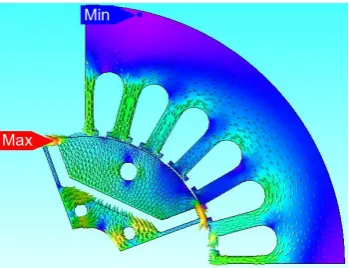
[image:5.595.83.494.376.497.2]Figure 6. Magnetic density map in stable operation.
Conclusion
In this paper, a multiphysics simulation model for PMSM vector control is established based on the field-circuit direct coupling method. Compared with the traditional MATLAB / Simulink model, this model replaces the motor circuit analysis model in the traditional model with a finite element model that can reflect the electromagnetic field characteristics of the motor. Make the analysis results have better practical reference value. By analyzing the output results of the model under common working conditions, the rationality of the coupled model is verified. The establishment of this model is of great practical significance to reduce the gap between simulation scenarios and actual working conditions, alleviate the problem of disconnection between theoretical models and actual models, reduce the time required for system joint tuning, and promote the development of electric car drive technology.
Acknowledgement
This research was financially supported by Jiangsu Postdoctoral Research Funding (2018K011C), National Science Foundation for Young Scientists of China (Grant No. 51407131) and Natural Science Foundation of China (Grant No. 51877161).
References
[1] Yu Jiang, Yang Shichun, Li Yalun. Modeling and Simulation of Vector Control System for Permanent Magnet Synchronous Motor. Computer Simulation. 36 (2019) 179-183.
[2] Bak, Yeongsu, Jang Yun, Lee, Kyo-Beum. Torque predictive control for permanent magnet synchronous motor drives using indirect matrix converter. Journal of Power Electronics. 19 (2019) 1536-1543.
[3] Liu Xiangsheng, Zhou Zhengxin. Research on Vector Control of PMSM Based on Fuzzy PI. Lecture Notes in Electrical Engineering. 593 (2020) 1-9.
[4] Chao Wang, Qiang Gao, Jing Tang. An Implementation Method of SVPWM Modulation Algorithm. IOP Conference Series: Materials Science and Engineering, 646 (2019).
[5] Shiva, Badini Sai, Verma. MRAS Based Speed Sensorless Vector Controlled PMSM Drive. Advances in Intelligent Systems and Computing. 1039 (2020) 549-556.
[6] Wu Guoqing, Chen Zhijun, etc. Simulation of vector control strategy of PMSM based on MATLAB. Applied Mechanics and Materials. 44 (2011) 1782-1786.
[8] Wang Jing, Wu jianhua, Sun Qingguo. Field-circuit coupled design and analysis for permanent magnet synchronous motor system used in electric vehicles. 2017 20th International Conference on Electrical Machines and Systems, ICEMS 2017. 2017.
[9] Xie Xiaogang, Chen Jin. MATLAB / Simulink simulation of vector control system for permanent magnet synchronous motors with Id 0. New Industrialization, 6 (2016), 47-54.