2017 2nd International Conference on Software, Multimedia and Communication Engineering (SMCE 2017) ISBN: 978-1-60595-458-5
Design and Implementation of Portable Development
Framework in Signal Processing Platform
Wan-wan LI, Bo GAO
*and Yong-jun LIU
Information Engineering University, Zheng Zhou 450000, China
*Corresponding author
Keywords: Domain modeling, Model driven, Signal processing.
Abstract. In order to solve the problem of the complex system, the hard development and the wide areas of high-speed signal processing platform, a portable development framework based on domain modeling is proposed. The meta-model is modeled in signal processing area and its template is designed based on Django, which can achieve the code generation automatically of software and hardware code combing with assembler file of meta-models. Finally, the framework code that connects processors into signal processing platform is automatically generated. In this paper, FPGA heartbeat package component development process as an example can verify the feasibility of the framework.
Introduction
Now the design and development of high-speed real-time signal process system is becoming more componentization, modeling and platform. Application can be ported quickly between different platforms through model-drive development technology. Most code generation tools only support PC system or simulation, and can not generate code in embedded devices. Then GUIGen4FPGA tool implements VHDL code generation in FPGA or ASIC platform using the method of developing stream[3], which solves the problem of VHDL code generation in special processors. However, how to implement component-based framework code generation on a much larger and more complex software-based information processing development platform is still a tricky issue. In [1], a method based on modeling is proposed to abstract and describe the system, and the automatic generation of CPU component frame code is realized. However, there are a large number of different types of processors in the signal processing platform, such as FPGA, DSP, GPP, etc., software radio system often requires a variety of processor collaboration.
This paper proposed an efficient development framework to design common components for signal processing platform based on modeling method. This approach can shield the differences of hardware and construct a uniform development framework, which is suitable to application development as well as component management. At the same time, model-drive makes the framework portable. So the hardware developer need not consider hardware, only focus on the application development, which can realize the reuse of the components.
The Design of the Portable Development Framework
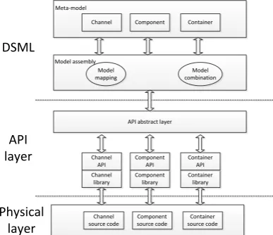
framework consists of three layers: the DSML layer, the API layer, and the physical layer. As shown in Figure 1:
Component Container Channel
Model
mapping combinationModel
API abstract layer
[image:2.595.207.401.101.268.2]Component library Container library Channel library Component API Container API Channel API DSML API layer Component source code Container source code Channel source code Physical layer Meta-model Model assembly
Figure 1. Portable Development Framework.
The physical layer mainly stores the source code files. API layer can create, modify and delete the source file. Through the API function and library, the physical layer and DSML layer can be connected. In addition, due to the difference between the code type and the code generation conditions about each meta-model, the API layer also includes the API abstraction layer, which is a collection of API functions of various source codes. The DSML layer consists of two parts: the meta-model of the source code and the model assembler. The meta-model provides a unified view of the hardware and software designers, each of which corresponds to the corresponding template file. The model assembler is mainly responsible for the visual assembly of meta-models such as drivers, components, containers, software packages, including model mapping, model synthesis and model verification[6]. The main function of the model synthesis module is to design the source file structure using the graphical symbols defined in the meta-model. After the structure design of the source file is completed, the model validation module checks whether the composite structure matches the API of source code generation, that is, whether the code of the source file can be generated by calling the appropriate module through the API layer. Finally, through the model mapping module, build a rule that maps the visualization model to source code.
The Construction of Domain Model
The advantage of domain modeling is the flexibility to define symbols to solve specific problems, so that engineers can quickly become familiar with the development environment[7].
Channel Modeling. The channel is a device driver in the ATCA platform, including a 10G network, Gigabit Ethernet, Fast Ethernet, PCI-e, and RapidIO, which can be defined as a multivariate: Channel = (ID, Type, Port, Constraint, Attr), where ID is the identity of the channel, Type is the processor type of the channel, Constraint is the constraint file on the channel of the FPGA processor, the channel on the GPP and DSP processor does not have the constraint file.
Component Modeling. Component is the most basic meta-model in the domain model, represented by the multivariate group Comp = (ID, Port, Attr, Func), where ID is the unique identifier of the component; Port is the set of all the ports of the component, Attr is the set of component attributes, Func is a collection of component functions.
Connector Modeling. A connector is a bridge between components that can be used to implement component connectivity and information interaction. It is represented by a multivariate conn = (ID, Type, Src, Dst, Attr), where ID is the unique identifier of the connector; depending on the connector function, it can be divided into three types: ctrlConn control connector, recvConn Connector, and sendConn send connector; src and dst, respectively, represent the source component number and destination component number, which are determined by the component ID and Port; Attr describes the attribution and type of connector.
Container Modeling. A container is a standard operating environment for a component[8], also is a composite meta-model and its model needs to be dependent on the connector. Define the container as a multivariate: Container = (ID, Conn, type, Attr), where ID is the unique identifier of the container; Conn is the set of connectors in the container; type is the type of container, Which can be divided into CPU containers, DSP containers and FPGA containers; Attr is used to describe the property information, including the type of connector, the number of each type.
Model-to-Code Mapping
In order to achieve the code generation from the model, this paper uses a template-based approach. The template defines how the mapping model element becomes the target platform structure and produces a source code fragment that can synthesize the source code file. The template-based code generation process improves the separation of concerns in the mapping specification, and each script is associated with a single or multiple model elements that are converted to source code fragments.
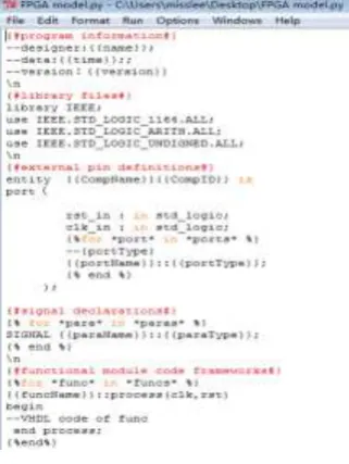
[image:3.595.217.378.440.654.2]Template is mainly used to achieve from the meta-model to VHDL code conversion, Python is a multi-purpose programming language, with a portable, mixed and other advantages, but also often play the role of scripting language. Because the software communication architecture involves a variety of fields and a variety of programming languages, therefore, this paper designs template file based on the grammar of Django framework which realizes in Python language. To components, for example, meta-model components corresponding to the template shown in Figure 2:
Figure 2. Component template.
The module's template contains five parts: program information, library files, external pin definitions, signal declarations, and specific functional module code frameworks. Each meta-model in the domain is designed with a corresponding template file.
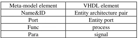
Table 1. Mapping Rules.
Meta-model element VHDL element
Name&ID Entity architecture pair
Port Entity port
Func process
Para signal
In Table 1, the ID of the meta-model is mapped to the entity schema pair in VHDL with the name in Attr. Correspondingly, Port and Func are mapped to entity ports and processes for VHDL, respectively. The component parameter Para is mapped to a signal in VHDL.
Combination of Meta-models
In the meta-model code generation, the model mapping module maps each meta-model to the corresponding hardware description language code[9]. After the model is assembled and stored, the model assembly file is exported through the model synthesis module. The model assembly file contains information about all the meta-models contained in the model to describe its own assembly and interconnection between components. This paper specifies the format of the model assembly file as shown in Figure 3, in the form of text to record the combination of meta-model. The semantics of the connection between meta-models are as follows:
<MetaModel_name>. <MetaModel_id> (port) <= <MetaModel_name>. <MetaModel_id> (port) Where MetaModel_name is the name of the meta- model, metaModel_id is the index number of the meta model, and port is the port to which the two meta-model connections.
Figure 3. Meta-model assembly file.
Verification of the Portable Development Framework
data port. The number of control connectors in the container model corresponds to the number of components. The number of the sending connectors corresponds to the number of data ports sent by the component, and the number of the receiving connectors corresponds to the number of the receiving data ports. Create a component model in the visual development environment, set the name of the component, attributes, etc. add ports for the component, and set the name, type, and orientation of the port. Create a container model, set the name of the container, attributes and other information for the container to add a control connector to control the heartbeat package, add a send connector to achieve the container and the data exchange between components, set the connector name, type, attributes, etc. This paper uses the method of building a driver library to implement the portable driver. Depending on the type of processor, the platform type, select the desired channel from the driver library using the driver API function.
In the visual development environment, connect the component and the container, the container and the corresponding interface of the driver and then use model assembler to export the meta-model assembly file. The model template is generated by the model synthesis module in the assembler. According to mapping rules from the template to VHDL language, combined with the model mapping and model validation module, generate the model of the source file, and then store in the program's model file.
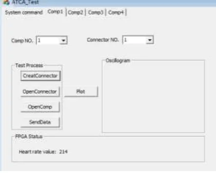
[image:5.595.186.408.443.621.2]In this paper, the development environment of the portable development framework is VS2010 and Python2.7.2. The framework generated program code (VHDL language) is compiled and verified in ISE14.7. The hardware developers only need to fill in the concrete implementation of the component framework source Code, there is no need to focus on components and platform interconnection part. Figure 4 is visualization management interface of FPGA component in ATCA platform. The interface of the FPGA's heartbeat packet components continues to send incremental random number, the current display is the packet ID. Therefore, the VHDL code generated by the portable development framework can be used in conjunction with the code written by the developer manually to meet the reliability requirements of the signal processing platform code auto-generation technology.
Figure 4. Visual management interface.
Summary
Acknowledgement
This research was financially supported by the National Key Technology Research and Development Program (2013BAH56F00)
References
[1] Du H, Peng H, Ma J, et al. Automatic code generation framework for heterogeneous processing platform[J]. Application of Electronic Technique, 2016.
[2] Wehrmeister M A, Freitas E P, Pereira C E, et al. GenERTiCA: A Tool for Code Generation and Aspects Weaving[C]// IEEE International Symposium on Object Oriented Real-Time Distributed Computing. IEEE, 2008:234-238.
[3] Pham D. Omnimount Systems Stellar G304 User Manual, Owner‘s guide and Instructions - TBM018307340030[J]. 2014.
[4] Moreira T G, Wehrmeister M A, Pereira C E, et al. Automatic code generation for embedded systems: From UML specifications to VHDL code[C]// IEEE International Conference on Industrial Informatics. IEEE, 2010:1085-1090.
[5] Sprinkle J, Karsai G. A domain-specific visual language for domain model evolution[J]. Journal of Visual Languages & Computing, 2004, 15(3–4):291-307.
[6] Wang Hai-lin, Li Jian-fen, et al. Meta-modeling based on MetaEdit+ [J]. Application of Computer System, 2011, 20(6):192-195.
[7] Stucki M S. Embedded Domain-Specific Languages for Scientific Modeling[J]. General Information, 2013.
[8] Walter T, Parreiras F S, Staab S. An ontology-based framework for domain-specific modeling[J]. Software & Systems Modeling, 2014, 13(1):83-108.
[9] Moutinho F, Pereira F, Gomes L. Automatic generation of graphical user interfaces for VHDL based controllers[C]// IEEE International Symposium on Industrial Electronics. IEEE, 2011:1491-1496.
[10] Guo Z, Buyukkurt B, Najjar W, et al. Optimized Generation of Data-Path from C Codes for FPGAs[C]// Design, Automation and Test in Europe, 2005. Proceedings. IEEE, 2005:112-117 Vol. 1.