5
IX
September 2017
Parameters That Effect Diamond Wire Cutting
Process
Mustafa GUL 1, Omer Faruk ERGIN 2, Ibrahim UZMAY3
1, 2, 3
Mechanical Engineering, Erciyes University
Abstract: In today's decorative stone industry wire saws are frequently used due to flexibility, low vibration and noise characteristics with high precision The main problem in practice, wire cutting machine; the life of the rope and breaking with the inability of the time foreseen.A stone cutting machine which is composed of steel rope, cutting tool and drive pulley; mechanism natural frequency was examined by different design parameters. The forced vibration character trying to determine to occur by cutting tool contact with the stone, the dynamic loads from the driving the ropes have been identified. Cutting speed and cutting force In performed analysis is considered as the basic design criteria. Thus, the rope-cutter mechanism design parameters selection, which will improve the of cutting conditions and are working in the direction to increase the operating life. Keywords: Wire saw, cutting speed, vibration analysis.
I. INTRODUCTION
In this study; a wire saw with a diamond cutters’ vibration analysis have done which is frequently used in the cutting of hard bodies in plate form. It is frequently used in today's stone industry because many plates can be cut at the same time as a saw in this structure. These systems have the disadvantages of multiple plate cuts, less chip removal than a rotary saw, and a smoother surface, and some disadvantage like the slowness of the cutting speed and the inability to predict the breaking time of the rope carrying the inserts. Wickert and Mote have worked to determine the modal analysis, eigenvalue and natural frequency of the system with free vibration made by a rope with a pre-tension motion in the horizontal direction [1-2]. Pakdemirli and his colleagues have been investigating the acceleration of the rope movements [3]. Huang and Mote have worked on the damping of similar structures, while Ying and Tan have studied the active vibration control of ropes [4-5]. Naguleswaran and Williams used the Galerkin method in their analyses to investigate the vibration effect of the pre-tension [6]. In his work, Chen showed that the load on a moving system between two supporting points of a moving cable increases the natural frequency [7]. Wang et al. have determined the error ratios of the vibration analysis on the wire saw model, which is considered as a continuous system in work [8]. In Huang and Xu's study, the fracture zone of the ropes used for stone cutting was examined in micro and macro dimensions, resulting in almost all of the fracture patterns being fatigue [9]. In a study by Turchetta and colleagues, a better chip lifting amount and homogeneous load distribution at the cutting edges were obtained in the design of a new stone cutting machine and in the tests made as prototype fabrication [10].In the data obtained from these studies, the effect of vibrations of the magnitudes occurring in the system during cutting operation.
II. CONTINUOUSVIBRATIONMODEL
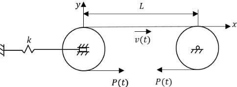
[image:2.612.192.434.588.677.2]The physical model of the system to be investigated will be considered as a continuous wire passing through variable speed between two drums.
Fig. 1. Coordinates and geometry
Where is the prestress in the rope, is the unsteady velocity in the axial direction of the rope, is the rope length between
The free vibration characteristic of the system given the physical model in the vertical direction is calculated using the Hamilton principle as follows.
2 10
t tKE
PE dt
(1)In the above equation, kinetic energy, represents potential energy. The boundary between the two drums is considered a boundary condition. Kinetic energy; 2 2 0
2
LA
dy
dy
KE
v
v dx
dt
dx
(2)
, , are the density of the rope, the cross-sectional area, and the velocity in the horizontal direction, respectively. represents the displacement in the vertical direction, corresponds to the displacement in the axial direction.Potential energy is;
2
0
2
L
EA
PE
Pe
e
F
dx
(3)At equation (3); represents pre-tension factor in the rope, modulus of elasticity of the rope, Δ proportional elongation, is the
total deflection in the axial direction [3]. Proportional elongation;
1 2 2
1
dy
1
e
dx
(4)Using equations (1-4), eq.(5) forms;
2 1 2 2 2 2 1 2 2 0 1 2 2 2 2 2
1 1 0
1 1 2 1
2
t L
t
A dy dy dy dy
v v v
dt dt dx dx
dy
P dxdt
dx
EA dy dy
F dx dx
(5)After the required arrangements have been made and high order processes have been eliminated, the following equation (6) has been obtained;
2 2
2
2 2 2 0
d y dy dy dy d y
A v v Av P
dt dx dt dx dx
(6)
Meirovitch proposed a solution by the Galerkin method in his work [11]. Which is;
1
,
( ) sin
n i i
y x t
q t
i x L
(7)As mentioned equation (7),
q
i refers to the generalized coordinate system. Arranging equation (6-7) eq.(8) forms.
1 2 2sin 2 cos
cos sin i i n i i i
Aq i x L Av i L q i x L
R Av i L q i x L
P Av i L q i x L
By using Galerkin method to eq (8);
0
( )
0, j=1,2,....n.
L
j
Rw x dx
(9)
( )
sin
j
j x
w x
L
(10)If equations (8) and (10) are to be written in equations (9) as a result of the necessary integers,
Mq Cq
Kq
0
(11)
0
sin sin
2 , if 0, if
L
ji
m i x L j x L dx
L i j
i j
(12)
0 2 22 c o s s in
0 , eğ e r
0 , eğ e r , 2
4 , if , 2 1
L
ji
c iv L i x L j x L d x
i j
i j i j n
ijv j i i j i j n
(13)
2 2 0 2 2 2 2 sin sin cos sin 2, if0 ,if , 2 2 ,if , 2 1
L ji
P
v i L i x L j x L
A
k dx
v i L i x L j x L P
v i L L i j
A
i j i j n
vij j i i j i j n
(14)The general motion equation of the system will determine the matrices derived from equations (12-14). The dimensions of the matrices to be created will increase the order of the system, which will affect the precision of the result [3]. For the equation (7) mentioned above, three differential equations are obtained as a result of a three-term series expansion.
1 2 3 1 2 3 2 2 1 2 3 2 21 0 0
0 1 0
0 0 1
Equation (15) shows that;
The speed and acceleration of the rope in the horizontal direction, The length of the rope between the drums,
Wire pre-tension,
Wire density and cross-sectional area,
It is understood that the above conditions have an impact on natural frequency.
Table 1. Characteristics of the system Distance
between durms
L (m)
Wire diameter
D (mm)
Wire
density (
Kg/m^3)
Pre-tension P
(N)
Wire velocity
v (m/s)
4 7.2 7810 1500 20
With equation (15), system has three natural frequency; +52.5357i
+15.1658i + 0.0491
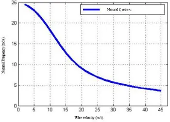
[image:5.612.229.404.350.476.2]Considering that the speed of the rope is 20 m / s in the horizontal direction, it is observed that the natural frequencies and the speed of operation are not coincident with each other.
Fig. 2. Wire-speed natural frequency change
Figure 2 shows the variation of natural frequency in the direction of movement of the rope in the horizontal direction. Although the system can be in third order, the other two frequency values will be in the imaginary region and therefore will not be meaningful in
the graph. A range of 45 , which is an attainable speed value, was selected starting from 2 as working speed.
[image:5.612.205.408.551.709.2]In Figure 2, the amount of stress and the natural frequency of the workpiece during the cutting are examined. The wire must be able to carry out uniform abrasion on the stone. From this point of view, stress is a parameter that directly affects the output of the system.
III. CUTTINGFORCESDURINGDIAMONDWIRECUTTING
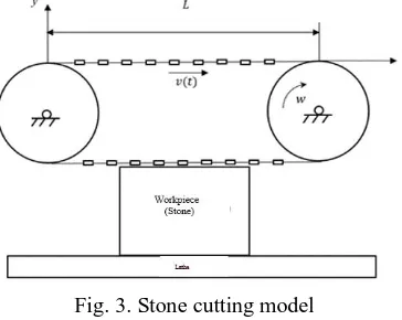
In the previous section, parameters affecting the natural frequency of a continuous system that is not under load have been expressed. In this section, it will examine that the contact between the workpiece and the cutting rope and the forces that will be generated as a result of the progress. Figure 3 schematically illustrates the stone cutting operation.
Fig. 3. Stone cutting model
[image:6.612.227.409.196.341.2]In Figure 4, the force relation between the cutting diamond tool and the stone to be cut is examined for force analysis.
Fig. 4. Effective forces on each diamond cutting edge
Where: P; tension; F
sfrictional force between cutting tool and stone; Fmthe centrifugal force of the cutting tool, and Ft the
normal force between the cutting tool and the stone, J denotes the radius of curvature.
Equations (16) and (17) for the applied forces in the x and y directions of the cutting tool are given in equations.
cos
cos
0
2
2
s
da
da
F
P
P
dP
(16)
sin
sin
0
2
2
n m
da
da
F
F
P
P
dP
(17)1
da
has known;cos
1
2
da
vesin
0
2
da
(18)
F
s
dP
0
(19)F
t
F
m
Pda
0
(20)
NJda
Pda mv da
2 (21)The normal force between the cutting tool and the workpiece has been found to be dependent on the J radius of the rope and the tension that the rope has caused during the cutting process.
IV. CONCLUSIONS
In this study, vibrational analysis of the stone cutting machine modeled as a continuous system was carried out and the parameters affecting the natural frequency of the system were examined and it was investigated whether the machining speed of the machine studied and whether other parameters are in the resonance region of the light. Besides, the operating conditions of the system under load are examined. It is expressed in relation to the curvature formed in the rope, the friction in the part, and the curvature in the rope. As a result of the work, it is possible to reach the result that the speed of advance due to the pre-stress in the case is very important. In the future, it is aimed to obtain the best cutting speed by considering the optimization of the tension with the speed of progress.
REFERENCES
[1] Wickert J. A. and Jr. Mote C. D. Classical vibration analysis of axially moving continua, Journal of Applied Mechanics, 57(3):738-744, 1990.
[2] Wickert J. A. and Jr. Mote C. D. Response and discretization methods for axially moving materials, Journal of Applied Mechanics Review, 44:279-284, 1991. [3] Pakdemirli M. , Ulsoy A. G. ve Ceranoglu A. Transverse vibration of an axially accelerating string, Journal of Sound and Vibration, 169(2):179-196, 1994. [4] Huang F. Y. ve Jr. Mote C. D. On the translating damp, ng caused by a thin viscous fluid layer between a translating string and a translating rigid surface,
Journal of Sound and Vibration, 181 (2): 251–260, 1995.
[5] Yıng F. ve Tan C. A. Active vibration control of the axially moving string using space feedforward and feedback controllers, Journal of Vibration and Acoustics, 118 (3): 306-312, 1996.
[6] Naguleswaran S. ve Williams C. J. H. Lateral vibration of band-saw blades, pulley belts and the like, International Journal of Mechanical Sciences, 10(4):239-250,1968.
[7] Chen J. Natural frequencies and stability of an axially-travelling string in contact with a stationary load system, Journal of Vibration and Acoustics 1119:152-157, 1997.
[8] Wang Fei et al. Error analysis of natural vibration characteristic od the diamond wire saw, Applied Mechanics and Materials, 541,542: 174-179, 2014. [9] Huang G. Q. ve Xu X. P. Analysis of the breakage of diamond wire saws in sawing stone, Key Engineering Materials, 304, 305: 123-126, 2006. [10] Turchetta S. Et al. A new sawing machine by diamond wire, Int J Adv. Manuf. Technol.,70:73-78, 2014.