© 2018, IRJET | Impact Factor value: 6.171 | ISO 9001:2008 Certified Journal | Page 1621
A Study of Infrastructure Development and Management of KoMet
(Kochi Metro Rail Limited).
Nandhu Prasad
11
Structural Engineer, Engineering Department, Devam Constructions, Kottayam, Kerala, India.
---***---Abstract - The public company Kochi Metro Rail Limited
(KMRL) was created in 2012, as a joint venture of the Government of India and Government of Kerala, to build and operate a 25-km long elevated metro system in Kochi, with 22 stations. Apart from the contribution from both governments (50%), this EUR 800 million project got partly funded by the French Agency for Development (AFD) – 20% -, and through private and cooperative bank loans (30%). Therefore, the discussion about building an elevated metro system in Kochi started in 1999; the project was approved by the Kerala Government in 2008 and by the Central Government in 2012. It was decided that the project would be implemented in a joint venture basis, with investments from the Central and State Government, and hence, a Special Purpose Vehicle (Kochi Metro Rail Limited) was formed in 2013. Assistance from AFD (French Agency for Development) was sought and approved in the same year, representing 20% of the total budget of the project (EUR 180 million). Despite this excellent level of service, the Public Transport network covered only 49% of the Greater Kochi, frequency of the bus service drastically came down after 8pm, there was no passenger information, the various modes of transport were not integrated and competition between public and private buses caused reckless driving. For all these reasons, the modal share for public transport came down from 73% to 49% in only 10 years (2005-2015). The other major challenges faced by Kochi in its development were the limited right of way, the lack of land availability and the need for open spaces. The works started in 2013 and were entrusted to DMRC (Delhi Metro Rail Corporation), a Centre-state owned company. We discuss regarding the construction aspects of the project, Need for metro, Advantage, Technical details, Study of civil construction drawings and contract, Safety Management, Site Visits are discussed in this internship report.
Key Words: Need for KMRL Metro, Advantage of KMRL, Technical details, Study of construction drawings and contract, Safety Management, Site visits, Pre-Stressing of U- Girder.
1. INTRODUCTION
Every city at a particular stage of growth reaches its state of saturation with respect to the transportation facility available. That city comes to a choked up state, at this state the transportation facility available with the existing infrastructure becomes really difficult and a large amount of time is required for moving from one part of the city to the other. Hence for improving the condition there is a need for the Mass Rapid Transit System (MRTS). The government
once it conceives the need for a MRTS in the city, it appoints an agency to undertake a study and recommend an appropriate MRTS. Based on the various factors such as per capita demand, peak hour demands, existing road condition, land usage pattern, forecasted population and traffic for the next 50 years etc. An MRTS is recommended by the agency and report is submitted. In case of Kochi the details obtained after conducting the study are as follows.
1.1 Population Density in Cochin Corporation Area
Population of Greater Cochin Development Authority (GCDA) area was 1.67 million in 1991 and 1.81 million as per 2001 Census. Population density is 2600 persons per sq. Km in GCDA area and 6300 persons per sq. Km in Cochin Corporation area. Population of Greater Cochin area has been growing at a rate of 1.4% per annum.
1.2 Registered Motor Vehicles
In the absence of a mass transport system, there has been a steep increase in the number of personalized motor vehicles in GCDA area. The number of registered motor vehicles in this area was 68,271 in 1987 and it grown to 4,46,959 in the year 2003. 64% of these vehicles are two wheelers. This large number of motor vehicles is resulting in rise in air pollution, increased number of road accidents, and slowing down of average vehicular speeds.
1.3 Traffic Demand Forecast
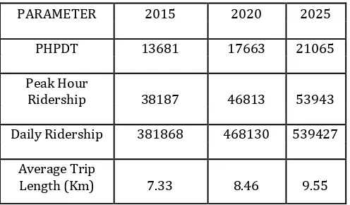
© 2018, IRJET | Impact Factor value: 6.171 | ISO 9001:2008 Certified Journal | Page 1622 Thripunithura Corridor. Summary of the Transport Demand
[image:2.595.36.284.158.303.2]Forecast for various years for Alwaye – Petta Corridor are given in table 0.1
Table 1: Kochi METRO Ridership on Alwaye to Petta Corridor
PARAMETER 2015 2020 2025
PHPDT 13681 17663 21065
Peak Hour
Ridership 38187 46813 53943
Daily Ridership 381868 468130 539427
Average Trip
Length (Km) 7.33 8.46 9.55
2. NEED FOR METRO
Public Transport System is an efficient user of space and with reduced level of air and noise pollution. As the population of a city grows, share of public transport, whether road or rail-based, should increase. Experience has shown that, in cities like Kochi where roads do not have adequate width and which cater to mixed traffic conditions comprising slow and fast moving vehicles, road transport can optimally carry 8,000 persons per hour per direction (phpdt). When traffic density increases beyond this level average speed of vehicles comes down, journey time increases, air population goes up and commuters are put to increased level, of inconvenience. In any case, it is not feasible to operate bus transport beyond 10,000 phpdt in mixed transport scenario, obtaining on Kochi city roads. With growing population and mega development plans coming up for this port city, the travel demand is expected to grow steeply. With inadequate public transport services, passengers will shift to private modes, which is already evident from the high ownership trends in the region. This will not only aggravate the congestion on the city roads but will also increase the pollution level.
Peak hour traffic demand on Alwaye-Petta Corridor has been assessed as 13,681 phpdt for the year 2015 and this is likely to increase 21065 phpdt by the year 2025. Road-based public transport, therefore, cannot meet this demand. There is an urgent need to introduce a light Metro system in the city to provide fast, safe, economic, and environment-friendly mode for mass movement of passengers. Carrying capacity of Light Metro System is upto 25,000 phpdt, which will be adequate to take care of the traffic problems for Greater Cochin area for the next about 25 years.
3. ADVANTAGES OF METRO SYSTEM
Requires 1/5th energy per passenger km compared to road-based system.
Causes no air pollution in the city.
Causes lesser noise level.
Occupies no road space if underground and only about 2 meters width of the road if elevated.
Carries same amount of traffic as 5 lanes of bus traffic or 12 lanes of private motor cars (either way), if it is a light capacity system.
Is more reliable, comfortable and safer than road based system.
Reduces journey time by anything between 50% and 75% depending on road conditions.
4. KMRL & DMRC
Kochi Metro Rail Ltd. (KMRL) having its corporate office at Revenue Tower, Kochi is a Special Purpose Vehicle (SPV) setup by Government of Kerala (GoK) and Government of India (GoI) as wholly owned government company for the execution of Kochi Metro Rail Project. The GoI and GoK had nominated five directors each to the Board of Directors (BoD) of KMRL, which have 10 nominee Directors. KMRL had entered into an agreement with Delhi Metro Rail Corporation (DMRC) for the development of Kochi Metro Rail Project. This agreement attempts to balance the roles and responsibilities of KMRL as the project owner and the client, as well as of DMRC, the executing agency. KMRL would recruit and depute up to 30% of the required project execution staff to the DMRC project execution team and this staff would work under the administrative and technical control of DMRC during the execution of the project.
5. PROJECT PROFILE
Implementing Agency : DMRC
Metro Alignment : Alwaye to Petta
Total Length : 25.612 km
Elevated Stations : 22
Type of Stations : All elevated
Maintenance Depot : Muttom
Gauge : Standard (1435mm)
Estimated Completion Cost : Rs. 5182 crores
Design Speed : 90kmph
Journey time : 45 mins
Train : 3 coaches
Fare : Rs. 15 to Rs. 30
Capacity : 975 passengers
6. TECHNICAL DETAILS:
© 2018, IRJET | Impact Factor value: 6.171 | ISO 9001:2008 Certified Journal | Page 1623 2. Number of stations : 22, Aluva, pulinchodu, companypadi,
Ambattukavu, Muttom, Kalamassery, Cochin University, Pathadipalam, Edapally, Changampuzha park, Palarivattom, JLN Stadium, kaloor station , Lissie station, M.G Road, Maharajas college, Ernakulam South, Kadavanthra, Elamkulam, Vytila, Thykoodam, Petta.
3. Gauge: Standard gauge
4. Trains: Stainless steel, 3 coach trains, fully air conditioned with wide vestibules, automatic doors, air suspension, and maximum carrying capacity of a train is 6000 passengers.
5. Signaling: Communication based train control system with automatic train protection and automatic train operation.
6. Traction: 750V D.C traction with regenerative breaking.
7. Track: Heavy duty ballast- less track with a maximum speed potential of 90kms per hour and maximum operational speed of 85kms per hour-average commercial speed is 33kms per hour including station stops.
8. Ticketing System: Automatic fare collection with contactless smart cards for multiple journeys and smart coins for single journey.
9. Stations: Green stations with all passenger facilities such as toilets, escalators and elevators .the entire system is friendly to the physically challenged.
10.Car Depot: For servicing and stabling trains a car depot will be located at muttom in the vacant low lying unused paddy fields.
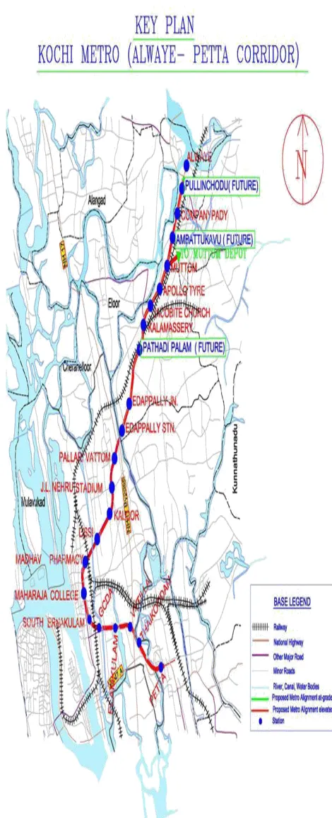
7. LOCATION AND LAYOUT
[image:3.595.144.543.88.744.2]Proposed stations along with the inter station distances between them are given in table below:
[image:3.595.318.553.101.679.2]Table 2: List of stations and inter station distances
© 2018, IRJET | Impact Factor value: 6.171 | ISO 9001:2008 Certified Journal | Page 1624
8. FUNDING STRATEGY:
[image:4.595.309.557.113.352.2]Out of the total Rs.5181.79 crore of completion cost, 35.85% would be met by Govt. Of Kerala which includes the cost of land also and 20.27% would be met by Govt. of India. The remaining 43.88% would be met by local/external borrowing.
Fig – 2: Proposal for a rationalization of bus routes.
9. STUDY OF CIVIL DRAWINGS AND CONTRACT
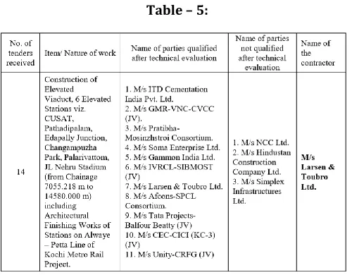
KMRL and DMRC signed an agreement for execution of the first phase of the Kochi Metro project. The agreement attempts to balance the roles and responsibilities of KMRL as the project owner and the client, as well as of DMRC, the executing agency. KMRL shall "exercise appropriate financial and technical oversight over the project's execution. DMRC invites tenders on behalf of KMRL and tender documents for works costing more than Rs.10 crore would be finalized by DMRC in consultation with KMRL. Tender acceptance would be done by a Tender Committee comprising DMRC’s and KMRL’s nominees. There were mainly four packages for civil works of viaduct and stations. DMRC floated two tenders at a time from the four work packages. A contractor can only be awarded a maximum of two contract packages, either in individual capacity or as a joint venture. For each of the work packages more than ten tenders were received. The evaluations of tenders were done in two stages-technical and financial evaluations.
[image:4.595.38.305.171.470.2]9.1 Details of Contract Packages
Table – 3:
9.2 Award of contract details for KC-02 contract
Table – 4:
9.3 Award of contract details for KC-03 contract
[image:4.595.305.558.316.521.2] [image:4.595.308.558.549.744.2]© 2018, IRJET | Impact Factor value: 6.171 | ISO 9001:2008 Certified Journal | Page 1625 9.4 Award of contract details for KC-04 contract
Table – 6:
[image:5.595.36.290.328.492.2]9.5 Award of contract details for KC-05 contract
Table – 7:
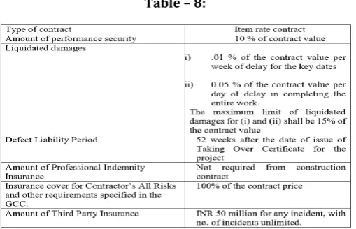
The following table depicts the key details of contract for each of the work packages (KC-2-5). It mainly involves the construction of elevated viaducts for Alwaye to Petta stretch including architectural finishing works of stations.
9.6 Key details of contract
Table – 8:
10. SAFETY MANAGEMENT
Construction sites are dangerous and notorious for serious accidents. Unfortunately each year, more construction workers are hurt and killed compared to any other major line of work, because of its dangerous nature. Construction accidents result in more than 1200 workers death every year around the country. This issue gets worse especially for a project like Kochi Metro Rail project where wide range of activities are carried out simultaneously in the middle of busy roads as well as in the precast yards.
Every contractor appointed by DMRC for the Kochi Metro Rail Project is required to undertake works in accordance with the applicable international guidelines, standards and specifications on SHE and would aim to achieve ISO certifications listed below:
a) OHSAS 18001-1999: Occupational Health and Safety Management System.
b) ISO 14001-2004: Environmental Management Systems 10.1 Safety Management by contractor
The safety management at the precast yards as well as at the construction sites was very well organized. For each precast yard there was a Safety management team employed at the site consisting of a Safety Manager, two assistant managers, and two supervisors under each assistant manager.
First step followed in the safety at the site was the Safety Induction Program carried out by the assistant manager to each and every one who is new at the site whether it be a worker or a visitor. In this he briefs about the common hazards occurring at the site, what are the safety measures to be followed and steps to be taken during case of emergencies and first aids.
PPEs: Every worker, employee or a visitor is provided with Personal Protective Equipment consisting of helmet, fluorescent jackets etc. It was mandatory for every worker to wear hard boots, gloves, goggles on violation of which he is liable to pay a penalty.
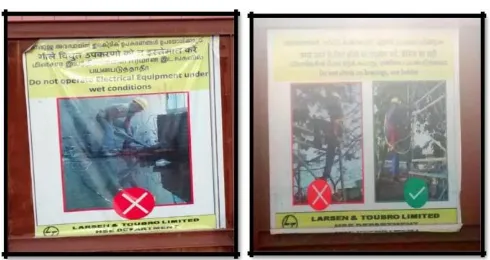
Sign boards: Appropriate sign boards were placed wherever needed. The entire site was barricaded to prevent the entry of unauthorized persons. Special guard rails (painted in yellow and black) were provided at places of pre-stressing work to prevent unauthorized entry. Sign boards denoting “Emergency Assembly Point” are provided where workers are to assemble in case of emergencies.
[image:5.595.36.291.584.748.2]© 2018, IRJET | Impact Factor value: 6.171 | ISO 9001:2008 Certified Journal | Page 1626 Fig – 3: Safety Precaution boards
Checklists: Various checklists were used at site by the safety engineers/managers. The activity can be started only after getting the permission from the inspecting safety officer. The safety officer in charge grants the permission when all the criteria in the checklists have been followed. Some of the checklists used are mentioned below
Crane Inspection checklist.
Gantry Crane Inspection checklist.
Confined Space Entry Permit.
Hot Work Permit.
Permit to work on plant, Machinery & Other power driven equipment.
Equipment Fitness report.
Preliminary Incident report.
Fire extinguisher Inspection Register.
Piling Rig Daily Checklist.
Piling Rig Inspection Checklist.
Plant Inspection Checklist.
Excavation Clearance Permit.
Analysis of First Aid cases.
Preliminary Incident Report.
Incident Investigation Report 10.2 EHS Inspections
1. Planned general Inspection: They are conducted at predetermined intervals by officials of L&T and DMRC. These inspections are conducted monthly by L&T officials and subcontractors. Weekly inspections are carried out by construction supervisors and daily inspections by L&T site EHS team.
2. Routine Inspection: It refers to inspection of work site, equipment and temporary structures performed by site and equipment operators. It includes daily inspection of plant and equipment by operator, weekly inspection of scaffold by scaffolding supervisor, monthly inspections of electrical hand tools by electrical supervisor, quarterly inspection of temporary electrical systems, and annual inspection of lifting appliances, equipment and gears by government approved competent person.
3. Specific Inspection: They are performed on activities without predetermined date by competent supervisors for ensuring whether an activity is executed in
accordance to a general set of rules/ method statement. These include inspections performed before a heavy lifting operation, inspection of formwork before connecting by formwork erector, mandatory inspection by Labour Department of Government, DMRC site EHS management team. The following are the examples of specific inspections conducted commonly at the site:
-Inspection performed before a heavy lifting operation.
-Inspection before and after the entry of a person into confined space.
-Inspection performed before and after welding and gas cutting operation.
-Inspection of formwork before concreting by formwork erector
10.3Safety Consultant (IQSC)
IQSC implies the Independent Quality and Safety Consultant appointed for Quality and Safety monitoring. The purpose of SHE audit is to assess potential risk, liabilities and the degree of compliance of the construction safety, Health & Environmental plan. Monthly Audit Rating Score (MARS) will be performed by a team consisting of contractors, KMRL and IQSC’s representatives based on the pre designed score-rating format.
KMRL has appointed Deutche Bahn International GmbH, Germany as the consultant for safety audit. Some of the functions of this independent consultant are:
To ensure that every contractor associated with Kochi Metro project comply by OSHAS 180011999 and ISO 14001-2004 standards.
To ensure the compliance of the contractors with the formulated and approved SHE policy.
To review safety policies and practices.
Review the contractor’s monthly SHE report.
Conduct regular visits or inspections to the sites to check unsafe practices and suggest remedial measures. Monitoring Documentation: IQSC will review the following documents of the contractor:
a) SHE policy and manual. b) SHE rules and regulations. c) SHE organization chart.
d) Annual SHE objectives/programs.
e) Accident/near miss statistics and analysis. f) SHE training program/records for all personnel. g) Operating manuals and maintenance manual of all
equipment.
h) Safe worthiness certificates of all lifting appliances and gears.
i) Medical fitness record for all personnel.
j) Risk identification, assessment and control details. k) Environmental management reports.
© 2018, IRJET | Impact Factor value: 6.171 | ISO 9001:2008 Certified Journal | Page 1627 to protect against safety and/or health hazards. Primarily
PPEs are:
a) Head Protection (Safety helmets)
b) Foot Protection (Safety footwear, Gumboot, etc.) c) Body Protection (High Visibility clothing
(waistcoat/jacket), Apron, etc.)
d) Personal fall protection (Full Body harness, Rope-grip fall arrester, etc.)
e) Eye Protection (Goggles, Welders glasses, etc.) f) Hand Protection (Gloves, Finger coats, etc.) g) Respiratory Protection. (Nose mask, Scab’s, etc.) h) Hearing Protection (Ear plugs, Ear muffs, etc.) 11. CONSTRUCTION DRAWINGS
Study was carried on the various structural and architectural drawings. The structural drawings can be broadly classified into alignment drawings, details of superstructure drawings, pile, pile cap, pier, pier cap, u girder & I girder drawings and also station drawings. Drawings common to all the 4 contractors were incorporated under common drawing section and rest of the specific locations were given under the each contract package number label.
[image:7.595.347.559.96.332.2]11.1 Few typical drawings and salient features
Fig – 4: Cross section of different types of pier The normal pier is used in alignment locations where the centre of the metro viaduct and the road median are same. i.e. at places where the viaduct passes through the centre of road meridian.
[image:7.595.320.561.413.691.2]The cantilever and the portal type of piers are used at locations were the alignment of metro and the median of the road vary. That is at places were the metro alignment has horizontal curves.
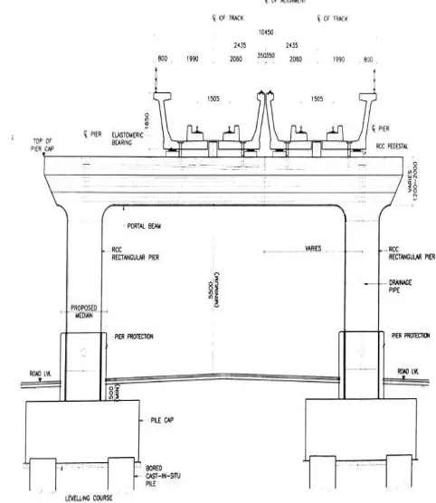
Fig – 5: Cross section of Standard U – Girder span with Cantilever/L-Pier
[image:7.595.55.285.414.639.2]© 2018, IRJET | Impact Factor value: 6.171 | ISO 9001:2008 Certified Journal | Page 1628 11.2 Cross section of the road section - post construction
[image:8.595.348.554.94.481.2]scenario
[image:8.595.60.243.110.331.2]Fig – 7: Post construction scenario at normal pier location
Fig – 8: Post construction scenario at Portal pier location The above drawings show the dimensions of the road after the post construction stage issued to the contractor. The electric line and other utility lines are made under ground and provision for that is also shown in the drawing. 11.3 Cross section of different type of station
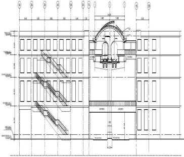
The metro stations are of three types. Type I, Type II and Special stations. The Type II stations are constructed at places where there is limitation in road space and hence the Entry Exit buildings vary in the plan from Type I. The Type I is constructed at places where enough amount of land is available for the station works. Special stations are stations like JLN station that have peculiar features other than the Type I and Type II.
[image:8.595.63.220.391.525.2]Fig – 9: Type I Station
Fig – 10: Type II Station
The construction methodology to be adopted for the construction of type I stations is shown in the below drawings. It is proposed to be constructed by different stages the first 4 stages are shown in the figure.
[image:8.595.334.516.581.737.2]© 2018, IRJET | Impact Factor value: 6.171 | ISO 9001:2008 Certified Journal | Page 1629
12. CONSTRUCTION METHODOLOGY
12.1 Substructure
The size of pier for the Kochi metro is limited to 1.2m circular for most of its height so that it occupies the minimum space at ground level where the alignment often follows the central verge of existing roads. Piers having circular or rectangular cross sections are being constructed. The station beams are rectangular and also piers of extended pier cap and other special superstructures are also provided with rectangular. To prevent the direct collision of vehicle to pier, a Jersey Shaped crash barrier of 1.0m height above existing road level has been provided all around the pier. A gap of 25mm has been also provided in between the crash barrier and outer face of pier. The shape of upper part of pier has been so dimensioned that a required clearance of 5.5m is always available on road side beyond vertical plane drawn on outer face of crash barrier. In such a situation, the minimum height of rail above the existing road is 8.5m. Cantilever or portal piers would be provided in case of curved paths.
The various components of substructure are:
Pile /Open foundation
Pile cap
Pier- Normal, Portal, Cantilever and Extended type
Pier cap
[image:9.595.53.268.485.689.2]Piling was done by cast in situ-bored piles with the help of hydraulic drilling rigs sing partial depth casing with Polymer and oscillator arrangement. Concreting was done by Tremie pipe method.
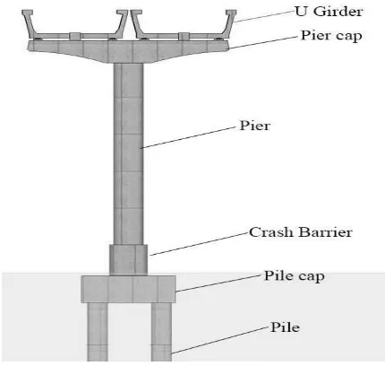
Fig – 12: Typical section of viaduct structure As most of the construction is to be carried out on the middle of the road, central two lanes including median would be required for construction activities. During piling and open foundation work, a width of 8m was found to be required for
construction and the same was barricaded. Barricades will be removed once the work on the piers and pier caps is completed for a stretch of about 200 meters, and shifted to another stretch, which will restoring the complete width of way for traffic.
The following sequences of activities were involved in construction of elevated viaducts:
12.1.1. Provision of utility and road diversion
It was done by conducting utility survey and providing alternative traffic arrangements by widening of existing roads and construction of Road over Bridges, flyovers etc. For the safety of the workers as well as the general public proper barricading and provision of temporary street lighting was also provided. During the period of construction, all utilities in the vicinity which were likely to be affected were shifted, in consultation with the departments concerned. Trees on the roadside, which infringe the working space, were cut, after obtaining permission from the Forest Department.
12.1.2. Construction of Pier
© 2018, IRJET | Impact Factor value: 6.171 | ISO 9001:2008 Certified Journal | Page 1630 sufficient workability (Slump of 120mm) is poured into the
pit through the tremie pipes. The concrete is mixed in the right proportion in the batching plants located somewhere near to the location of work in casting yards. From the casting yards, RMC trucks carry the concrete to the site of usage within the stipulated time so that the concrete does not lose much of its workability. If any mix gets delayed to reach the site, then that concrete will not be used in concreting for that affects the performance of the flow of concrete. Each batch of concrete from the RMC truck is checked for slump and cube tests. Also each truck carrying concrete also carries with it a note which gives information on the time of mixing. Using this, we can determine whether the mix is good for usage or not at the time of delivery. The tremie is always immersed in the concrete. But when concrete is poured into the pit, the tremie pipe is withdrawn slowly. When sufficient depth is filled with concrete, each segment of the pipe is removed from the top but always leaving the other end of the pipe within the concrete. Compaction of concrete is done by agitating the tremie pipe up and down vigorously. Whenever the concrete is poured into the pit, it displaces an equivalent volume of polymer- water mix which is collected into a tank.
Depending on the type of soil, loading etc. the number of piles in each pile cluster carrying the loads of the super structure varies. In the metro rail project construction at Kaloor, the pile cluster consisted of 4 to 6 piles. In case of 4 piles, each pile was located at the corners, for 5 pile system, one at the centre and for a 6 pile system; piles were located with 3 piles in one row. After constructing each pile, the next pile was constructed. Once the pile system at a location was completed, excavation was made to take out all the piles and usually the excavation was done to more than 1.5 meters deep. Once all the piles are dug out, the pile portion was chipped off manually up to the cut off level. Then a base of plain cement concrete was prepared for the construction of pile cap. Then reinforcements are laid to cast the pile cap. Subsequently, concreting is done over it and a small part of the reinforcements are made to project upwards which subsequently form the pier structure. A later on reinforcement is placed over the pile cap and is built upwards to gain the heights. Casings or shutters are placed with at most care around the reinforcement and is concreted using the concrete pumping equipment. Once setting has taken place, the shutters are removed and jute bags are placed around the structure and curing is done.
12.1.3. Construction of Pier Cap
The following are the activities involved in the construction of a pier.
- Leveling the formwork free/fixed end and support for bearing outstand.
- Closing the external formwork of pier cap.
- Application of shuttering oil or formwork releasing agent.
- Lifting and placing of reinforcement cage.
- Fix the anchor cones and check for their trueness.
- Placing of HDPE sheathing in the reinforcement as per profile.
- Placing and fixing the forms and completing of the formwork.
- Checking the dimensions and verticality of slides.
- Checking the boom placer and its working condition and make ready for placing concrete with such as priming, etc.
- Checking the vibrator for compacting concrete is working condition.
- Checking the quality control personnel available at site along with thermometer, slump cone and required number of cubes.
- Receiving concrete and check for its workability by slump cone and temperature.
- Due to congestion in the reinforcement/ sheathing/ void former/ anchorages, pour and compact concrete from the top and ensure there is no segregation.
- Stripping the side formwork.
- Wrapping hessian cloth and keep it moist always.
- Pier cap to storage/ stack yard and start curing by water sprinkling.
- The pre-stressing of strands would be done at the connection of pier and pier cap after the erection of pier cap
-12.1.4. Construction of pedestals and installation of bearing
The following are the activities involved: - Surface preparation.
- Shuttering works. - Casting of pedestal.
- Removal of formwork and curing.
- Installation of elastomeric bearing and steel plate.
-© 2018, IRJET | Impact Factor value: 6.171 | ISO 9001:2008 Certified Journal | Page 1631
13. TIME CYCLE FOR CONSTRUCTION
[image:11.595.36.270.136.368.2]13.1. Time cycle for construction of a normal pier
Table – 9:
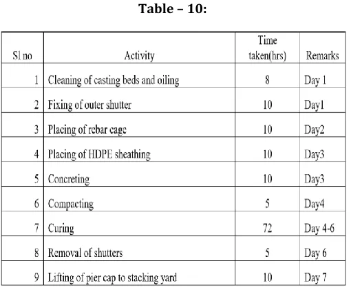
13.2. Time cycle for casting of pier caps
Table – 10:
14. SITE VISITS
14.1. Casting yard
The casting yard of both Soma Enterprise as well as L&T Ltd was visited during the internship period. The casting yard have facilities for casting beds, curing and stacking area, batching plant with storage facilities for aggregates and cement, site testing laboratories, reinforcement steel yard and fabrication yard etc.
The fabrication of following items is under taken at casting yard:
1. U-Girder 2. I-Girder
3. Pier Cap
4. Station Beams
5. Parapets
14.2. Health Centre
A health centre facility is provided in site. Minor injuries and first aid is given here. An ambulance is also provided here. A training hall is also provided to give training and orientation to workers with various safety and health related posters are displayed.
14.3. Health & Safety measures that were observed in casting yard
All workmen and staff wears safety gear such as helmet, safety shoes, fluorescent vest etc.
Persons are not allowed under suspended loads while lifting load.
The work area is properly barricaded.
Access control is exercised to check unauthorized person within construction area.
Safety orientation is given for workers as well as those who come for training in the site. Students coming for training in the site are provided with necessary safety gears.
Trailers and lifting devices (cranes and tackles etc.) are inspected before operations to safe working condition and validity of fitness certificate is checked.
Lifting equipments, gantries, tools and tackles and checked using competent third parties.
Trailers are fitted with side lamps, tail lamps, audible alarms etc for warning and safe transportation.
High mast lights in adequate numbers provided for visibility in night (as the site is running 24 hrs).
Regular inspections is done by the safety team of DMRC as well as the contractor
14.4. Plant/Machineries in casting yard
Casting beds.
Gantry cranes of 100 MT capacities – 2 Nos.
Gantry cranes of 80 MT capacities – 2 Nos.
Boom placers.
Mobile tyre mounted cranes.
Trailers for transportation of precast segments.
Dumpers.
Ready mix plants.
Transit mixers
Excavators
Bar bending machines
Diesel generators
[image:11.595.36.291.397.609.2]© 2018, IRJET | Impact Factor value: 6.171 | ISO 9001:2008 Certified Journal | Page 1632
Stressing equipments 14.5. Quality Assurance
Site testing laboratory
Concrete compressive strength, permeability tests etc. are conducted in the site itself and witnessed by contractor and DMRC representatives.
Inspections
14.6. Other facilities in casting yard
Site office for DMRC as well as contractors.
Canteen for workers as well as engineers.
Smoking area
Lemon water and drinking water points
Labour colony is also provided adjacent to casting yard for the workers
Security room at entrance
15. PRE-STRESSING OF U – GIRDER
The pre-stressing of U girder was observed at the casting yard. It consists of following stages:
15.1. Profiling
a) The strands are to be placed in to the rebar cage in the casting bed, to required spacing and dimensions.
b) The ends of strands are pulled through the anchor wall at either ends.
c) For de-bonding lengths as specified in the working drawing. HDPE pipes are inserted at either ends of the girder.
15.2. Stressing
a) Strands at either ends of the anchor walls are fixed to the loading frames with barrels and wedges.
b) At one of the anchor walls the strands are stressed (initial tension) using a mono pulling jack, which is to be placed between anchor frame and reaction frame. Maximum ram is kept to do de-stressing operation with the same jacks .The initial slackness in the jack is removed by using multi jack.
c) Profiling is checked for correctness, if necessary, error found is corrected.
d) 2X600 T jacks at one end of the frames are operated with a common pump. The stressing is carried out to the required force in increments as sequence given by the designer and the elongations are recorded in format. The tendons are locked at this force.
e) Clearance is given by engineer for main contractor to carry out the concreting of girder.
f) Utmost safety precautions are taken before, during or after stressing to prevent accidents.
g) Only trained persons are allowed to conduct the stressing operations. And were observed to wear safety equipments to protect them by wearing helmets and any other safety devices.
h) Full and accurate records of all operations connected with the pre-stressing are maintained. These records shall include the jack pressure and extension and slip, if any of each pre-stressing tendon.
i) NO de-tensioning of steel shall takes place until the concrete has attained specific strength as ascertained from the test on cubes cured and hardened under the same condition as concrete of the member.
15.3. De-tensioning of strands
a) Before de-tensioning the strands, ends of the strands are marked with marker, to measure the slip of the strands. This is observed during the de-tensioning process and measurements are recorded.
b) Release the pre-stressing force in the cables through multi jacks gradually.
c) The recorded measurements are checked with the engineer for his approval, this value is also checked with the respect to the values given in the drawings. 16. CAST IN SITU PILE (EDAPALLY SITE)
The cast in situ pile boring and concreting was observed at both Edapally viaduct stretch as well as at the station LHS entry structure site.
a) Boring of the Pile in Soft Strata:
After aligning the piling rig in position, boring in the top soil was done using the soil barrel buckets/ soil augers up to the non-collapsible depth. During the boring the verticality of the drilled hole was constantly checked and also the position of the bore was cross checked with the reference points. b) Installation of the Guide/ Temporary casing or
Permanent liner:
© 2018, IRJET | Impact Factor value: 6.171 | ISO 9001:2008 Certified Journal | Page 1633 c) Termination of Bore hole:
After reaching the designed depth the same was offered to Engineer-in-charge for inspection and review. The comments and suggestions from the DMRC site engineer were attended promptly. d) Cleaning of Bore Hole:
After attending the comments and suggestions given by Engineer-in-Charge after the inspection cleaning of the base of the bore hole was carries out with a cleaning bucket.
e) Lowering of Tremie pipe:
After placing the reinforcement cage tremie of appropriate diameter i.e. 200/250mm tremie pipe with hopper was lowered in to the bore hole. Before lowering the pipe it will be ensured that the joints are water tight and intact. The gap between the base of pile and bottom of the tremie was kept around 150mm since the bore hole was wet.
f) Flushing Operation:
Before the concreting starts the bore hole was flushed with Polymer slurry. During flushing, contaminated muck from the bottom of the pile is collected in a ground level tank through the tremie outlet. Flushing was continued till the density of the return mud was less than 1.06kg/cum. Bore was filled with fresh Polymer slurry before concreting.
g) Concreting:
The concrete brought from the plant is sampled for the slump, temperature and cube casting. After the site QC Engineer certifies the concrete is discharged directly into the hopper of the tremie. The plug was placed in the tremie before charging the tremie with concrete. After filling the tremie with concrete then the plug was removed. The concrete was then poured in to the tremie continuously. The tremie was withdrawn gradually as concrete rises upwards. When the concrete has reached above the cut-off level the concreting works were stopped. Once the concrete that has reached above the cut-off level was ensured to be sound, the guide casing was extracted from the bore hole. It was extracted vertically and no disturbance to the concrete and no mixing of the soil with the concrete were ensured.
17. CONCLUSION
The internship at Delhi Metro Rail Corporation, for four weeks, has definitely proved to be useful to me in number of ways. It helped us to relate the practical procedure on the field to the theories taught in the class. I had an opportunity to go through various documents used in the construction field like contract documents, method statements and various safety checklists. The training provided us a good deal of practical knowledge. We also had a chance to witness many of the activities at site and procedures involved in a
metro project. The managers and engineers at DMRC, SOMA Enterprise and L&T helped us a lot in understanding all those activities and clearing doubts.
18. REFERENCES
[1]The French team in charge of the coordination of the two-year Technical Cooperation between AFD (French Agency for Development), CODATU (Cooperation for a Development of a Sustainable Mobility in developing countries), SYTRAL (Transport Authority of the Rhone region) and KMRL (Kochi Metro Rail Limited). Ms. Marion Hoyez (CODATU), Mr. Etienne Lhomet and Ms. Laura Cornelis (DVDH) coordinated the edition of the document, under the supervision of Mr. Mathieu Verdure, Project Manager at AFD Head office, and CODATU team. [2]DMRC official construction report given to KMRL for its fulfillment. (Contract documents, method statements and various safety checklists).
[3] http://cochimetro.blogspot.in/2014/04/kochi-metro-rail-project.html