Methodologies for the Structured Development and
Documentation of Manufacturing Planning and
Control Systems
Mark Duncan Stirling
Business and Informatics Research Institute Information Systems Institute University of Salford, Salford, UK
If you think you can, you can. And if you think you can’t, you’re right
Mary Kay Ash
To my Father,
Table of Contents
Table of Contents... ii
Table of Figures ... vii
Acknowledgements ...ix
Declaration...x
Publications by the Author...xi
About the Author... xii
Abbreviations... xiii
Abstract...xiv
Chapter 1. Introduction to the Project ...1
1.1 Introduction ...1
1.2 Background to the Total Technology PhD Scheme...2
1.3 Background to Ferodo Ltd., Chapel-en-le-Frith Site ...4
1.4 The MRPII Software Package used – MFG/PRO ...8
1.5 Statement of the Area of Concern...9
1.6 Objectives of the Research...10
1.7 Research Framework...11
1.8 Research Methodology...13
1.9 Organisation of the Remainder of the Study...17
Chapter 2. Manufacturing Planning and Control Systems...19
2.1 Introduction ...19
2.2 Early Manufacturing Planning and Control Systems ...20
2.3 Manufacturing Resource Planning, (MRPII) ...24
2.4 Problems with MRPII Systems ...39
2.5 Capacity Planning...44
2.5.1 Master Production Scheduling ...45
2.5.2 Rough Cut Capacity Planning ...48
2.5.3 Capacity Requirements Planning ...49
2.5.4 Finite Capacity Scheduling...50
2.6 Just in Time...53
2.10 Systems Analysis and Design Methodologies ...71
2.11 Modelling Techniques...80
2.12 Database Development ...85
2.13 The MRPII Integration Problem ...91
2.13.1 Centralised Database Strategy...92
2.13.2 Distributed Database Strategy...93
2.13.3 Hybrid Database Strategy ...95
2.14 The Core and Sub-Systems Approach to Systems Development...96
2.15 MPC System Current Developments...97
2.15.1 The Extended Enterprise...97
2.15.2 Enterprise Resource Planning...98
2.15.3 Internet in Manufacturing ...99
2.15.4 Object-Oriented Programming ...104
2.16 The Documentation Problem ...107
2.16.1 The International Organisation for Standardisation Procedures...109
2.16.2 Development of Documentation...113
2.16.2.1 The Minimalist Approach to Documentation ...115
2.16.2.2 The Elaboration Approach to Documentation...116
2.16.3 Problems with Paper Documentation ...118
2.17 The Electronic Approach to System Documentation ...120
2.17.1 Document Management Systems ...125
2.17.1.1 Document Management Systems...125
2.17.1.2 Groupware Systems ...127
2.17.2 Documentation Intranets...129
2.17.3 Problems with the Electronic Approach to System Documentation...133
2.17.4 Specific Problems with Document Management Systems ...134
2.17.5 Specific Problems with Intranets ...135
2.18 The Ferodo OE Manufacturing Planning and Control System...136
Chapter 3. Structured MPC System Development...138
3.1 Introduction ...138
3.2 Case Study Companies ...140
3.2.4 Eurofriction Ltd...144
3.2.5 Ferodo Railways Division ...145
3.2.6 Case Study Findings ...146
3.3 Early Systems Development at Ferodo...148
3.4 Satellite Systems Integrated at Ferodo ...149
3.4.1 Quality Analysis System...151
3.4.2 Property Recording System ...154
3.4.3 Manufacturing Instructions System ...158
3.4.4 Batch Tracking Report ...163
3.5 Development of the Systems Development Methodology...165
3.5.1 The Three Integration Techniques...169
3.5.1.1 Incorporation...169
3.5.1.2 Common Characteristics of Satellite Systems ...171
3.5.1.3 Integrated Satellite Systems ...175
3.5.1.4 Joined Satellite Systems ...176
3.5.2 The Systems Development Life Cycle Methodology...177
3.5.2.1 Change in Business Requirements ...180
3.5.2.2 Process Changes ...181
3.5.2.3 New Module...183
3.5.2.4 Incorporated Integration ...184
3.5.2.5 Satellite System Integration...185
3.5.2.6 Core System Modification...186
3.5.2.7 Independent Package ...188
3.5.3 Systems Development Life Cycle Methodology Decision Support...189
3.5.3.1 Decision Support Questions...189
3.5.3.2 Indicative Ratios ...192
3.6 General Applicability of the Methodology...196
3.7 Problems with the Satellite Systems Approach...197
3.8 Structured MPC System Documentation ...198
3.9 The Ferodo MPC System Documentation...199
3.10 The Ferodo Intranet...201
3.10.1 The Ferodo Intranet for MRPII Documentation ...209
3.11.2 The Four Levels of Documentation...216
3.11.3 The New Systems Development Life Cycle Methodology ...222
3.11.3.1 Define System Boundaries...224
3.11.3.2 Modify the Template to Fit the System...227
3.11.3.3 Functionally Decompose Template...227
3.11.3.4 Apply PIPS to Decomposed Template...228
3.11.4 Document Storage and Distribution ...229
3.12 General Applicability of the New Methodology...230
Chapter 4. Validation of the Systems Development Life Cycle Methodology ...231
4.1 Introduction ...231
4.2 Interrogative Validation Techniques ...232
4.3 The Validation Interviews...236
4.4 The Validation Interview Results...237
4.5 The Validation Interview Findings ...242
4.6 Application of the Systems Development Life Cycle Methodology...244
4.6.1 Case Study Company A ...246
4.6.2 Case Study Company B ...248
4.6.3 Case Study Company C ...251
Chapter 5. Summary and Conclusions ...257
5.1 Summary...257
5.1.1 The Structured Development of MPC Systems ...257
5.1.2 The Structured Documentation of MPC Systems ...262
5.1.3 Key Elements of the Research...266
5.2 Conclusions...268
5.3 Recommendations for Further Work...271
5.3.1 The Structured Development of MPC Systems ...271
5.3.2 The Structured Documentation of MPC Systems ...272
Chapter 6. Appendices ...273
6.1 Quality Analysis Files ...273
6.1.1 Main Datafile...273
6.1.2 Headings Control File ...274
6.3.2 Standard Tests Control File ...279
6.3.3 Item Tests Control File ...280
6.3.4 Main Data Storage Datafile...281
6.3.5 Data Entry and Reporting ...283
6.4 Manufacturing Instructions Files...288
6.4.1 Index Headings Control File ...288
6.4.2 Data Field Headings Control File ...289
6.4.3 Main Data Storage Datafile...290
6.4.4 History Datafile ...291
6.4.5 Reporting ...292
6.5 The Structured Interview Template ...294
Table of Figures
Figure 1: Ferodo Divisional Structure ...5
Figure 2: Original Ferodo OE Division Information System...6
Figure 3: New Ferodo OE Division Information System ...7
Figure 4: The Action Research Cycle...15
Figure 5: Structure and Flow of Thesis ...18
Figure 6: Re-Order Point Theory ...21
Figure 7: Effect of Increased Demand on Re-Order Point Theory...22
Figure 8: MRP Logic ...24
Figure 9: MRP Calculation for a Disk Brake Pad Product Structure ...26
Figure 10: Sample Disc Brake Pad Bill of Materials ...26
Figure 11: Closed-Loop MRP ...29
Figure 12: MRPII ...30
Figure 13: The MRPII Database Structure ...33
Figure 14: Master Production Scheduling...46
Figure 15: Table of Machine Capacity against Load ...47
Figure 16: Hierarchical Factory Organisation Structure...51
Figure 17: The Deming Cycle...54
Figure 18: Kanban Control Techniques ...57
Figure 19: Effects of Lowered Inventory ...58
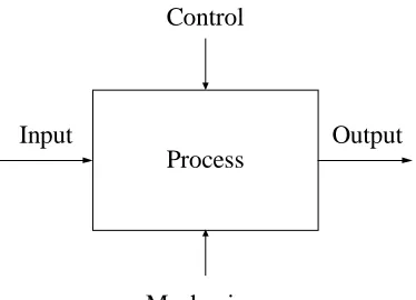
Figure 20: The Input - Output Diagram...80
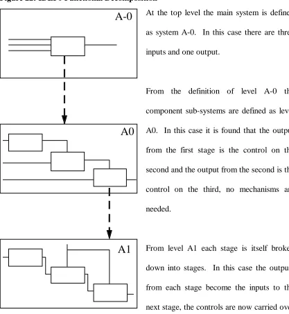
Figure 21: The IDEF0 Diagram ...81
Figure 22: IDEF0 Functional Decomposition ...82
Figure 23: Integrated Database Approaches ...87
Figure 24: Framework for Planning, Implementing and Managing an Intranet..132
Figure 25: Developed Ferodo OE Information System ...150
Figure 26: New Systems Database Construction ...165
Figure 27: New Systems Internal Construction...166
Figure 28: Summarised Systems Development Life Cycle ...177
Figure 29: The Systems Development Life Cycle ...178
Figure 34: New Summarised Systems Development Life Cycle With Feedback...223
Figure 35: The New Systems Development Life Cycle ...223
Figure 36: Analysis of Systems Analysis / MRPII Experience ...238
Figure 37: Analysis of the Requirement for a Methodology ...238
Figure 38: Analysis of the Systems Development Life Cycle Methodology ...239
Figure 39: Analysis of the Structured Questions...239
Figure 40: Analysis of the Indicative Ratios ...240
Figure 41: Analysis of the Methodology Extension to include Documentation...240
Figure 42: Analysis of the Top Level MPC Systems Documentation Template....241
Figure 43: Analysis of the PIPS Levels of Documentation ...241
Figure 44: Results of Validation Interviews...242
Figure 45: Decision Support Questions applied to Case Study Co. A ...247
Figure 46: Decision Support Questions applied to Case Study Co. B – Part 1 ...249
Figure 47: Decision Support Questions applied to Case Study Co. B – Part 2 ...250
Figure 48: Decision Support Questions applied to Mobile Data – Part 1...252
Figure 49: Decision Support Questions applied to Mobile Data – Part 2...255
Acknowledgements
Due to the nature of industrial research I am indebted to a number of people, especially:
Dr David Petty, (Federal Mogul Senior Lecturer in Manufacturing) and Professor
Trevor Wood-Harper, (Professor of Information Systems), my Academic Supervisors,
for their help and guidance.
Mr Jeff Bailey, (OE Business Analyst, Ferodo Ltd., my Industrial Supervisor), for all
the time he has devoted to answering my questions, for listening to and constructively criticising my developing theories and for supporting and assisting my work at Ferodo.
Mr Henri Ramczyk, (Director Light Vehicle Operations, Ferodo Ltd.), for providing
the support necessary for my project and for giving me unrestricted access to Ferodo.
In addition to these individuals special thanks must also go to John Roberts and David
Venables of Ferodo MIS, for fielding many questions and for helping me develop the
systems shown in this thesis and to Dr Mike Sheridan, of the Ferodo Quality Department, for allowing me to experiment with his quality systems.
Thanks must also be given to the rest of the staff of the Ferodo MIS department for their help with the technical development of the systems described within this thesis.
Declaration
Publications by the Author
1. Stirling, M.D., Petty, D.J. and Bailey, J. (1997), The Implementation of Integrated
Business Control Systems in a Manufacturing Company, Total Technology 20 Year
Celebration Poster Session, 26 June.
2. Stirling, M.D., Petty, D.J., Venables, D.J. and Harrison, D.K. (1997), Development
of an Integrated Manufacturing and Quality Control Information System - A Case
Study, Proceedings of the 32nd International Matador Conference, Formerly the
International Machine Tool Design and Research Conference, UMIST, 10-11 July, Pages 125-130.
3. Petty, D.J., Sutton, A.D., Bailey, J., Saxby, T.M. and Stirling, M.D. (1997), Manufacturing Planning and Execution Systems to Cope with Batch and
Semi-Process Material Flow, Advances in Manufacturing Technology XI, Proceedings of
the 13th National Conference on Manufacturing, Glasgow Caledonian University, 9-11 September, Pages 416-421.
4. Petty, D.J., Stirling, M.D., Travis, L.C. and Bennett, R. (1998), Finite Capacity Scheduling and Manufacturing Resource Planning Hybrid Production Control
Systems: Conditions for Successful Implementation, Advances in Manufacturing
Technology XII, Proceedings of the 14th National Conference on Manufacturing, University of Derby, 7-9 September.
5. Stirling, M.D. and Petty, D.J. (2000), Support for Service Functions: Integration
into an ERP Framework, Supply Chain Practice, Journal of the Supply Chain
Knowledge Centre, Cranfield School of Management, Vol. 2, No. 3, Pages 48-55. 6. Petty, D.J., Stirling, M.D., Travis, L.C. and Bennett, R., Finite capacity / MRPII
hybrid control systems: conditions for successful implementation, Accepted for
Publication in: The Journal of Engineering Manufacture (Short Communications): Proceedings of the Institution of Mechanical Engineers, Part B.
7. Stirling, M.D., Service Functions and ERP Packages – Mutually Exclusive?,
About the Author
The author left school in 1991 and started an undergraduate training scheme with AVRO International Aerospace. This training scheme was designed to compliment an engineering degree as part of a thick sandwich course. In 1992 sponsorship was provided by AVRO International Aerospace to undertake a Mechanical Engineering degree at Salford University. The author graduated with first class honours in 1995.
After graduating, a place was awarded on the Total Technology PhD scheme, co-ordinated by UMIST, to do a collaborative PhD with Ferodo Ltd., Chapel-en-le-Frith and Salford University. The project was based on-site at Ferodo Ltd.
The placement with Ferodo involved fulfilling the role of systems analyst, giving close operational support to the Business Analyst / Systems Manager, whilst also pursuing the research objectives of the PhD. In particular, responsibility was assumed for assisting with safeguarding the operation of the Manufacturing Resource Planning package used within Ferodo. Consultancy work was also undertaken for some of the companies within the same group as Ferodo and for suppliers to Ferodo in order to gain a breadth of understanding of business problems.
The author left Ferodo in July 1998 and started working for Minerva Industrial Systems Plc, a leading supply chain management software supplier, as an ERP consultant and then as project manager for the inventory management practice.
Abbreviations
ASCII American Standard Code for Information Interchange
BPR Business Process Re-Engineering
CATWOE Checkland’s System Definition Acronym
DMS Database Management System
E-R Entity Relationship
EMail Electronic Mail
EOQ Economic Order Quantity
ERP Enterprise Resource Planning
FCS Finite Capacity Schedule
GRASP Graduate Support Programme
HTML Hypertext Mark-up Language
IDEF International Definition
INC Internal Non-Conformance
ISO International Organisation for Standardisation
ISO9000 International Organisation for Standardisation Procedure 9000
IT Information Technology
JIT Just in Time
MPS Master Production Schedule
MRP Material Requirements Planning
MRPII Manufacturing Resource Planning
OE Original Equipment Division
OPT Optimised Production Technology
Purchase Order ID Purchase Order Identification Number
RAM Random Access Memory
RCCP Rough Cut Capacity Plan
ROCE Return on Capital Employed
ROP Re-Order Point
SPC Statistical Process Control
SSADM Structured Systems Analysis and Design Method
Abstract
Computerised Manufacturing Planning and Control, (MPC), systems are used by many manufacturing organisations and there has been a significant amount of research into the implementation and use of these systems. It is apparent that these systems, once implemented, require continuous development to meet changing business requirements. What is not well understood is the optimal approach for this development process. This thesis presents the findings of a collaborative industrial research project that addresses this issue. The collaborative partner was Ferodo Ltd., Chapel-en-le-Frith, a leading automotive friction product manufacturer. The project was conducted under the Total Technology scheme.
A review of the development of MPC systems is presented. This review considers three approaches to MPC; Manufacturing Resource Planning, (MRPII), Just in Time, (JIT) and Optimised Production Technology, (OPT). It is shown that whilst there is diversity between these approaches and their application in industry, there is convergence between their data structure requirements. The work presented in this thesis is based around the MRPII package used within Ferodo. The research concentrated on defining methodologies for structured systems development, with two main
themes:-1. The development of a multi-stage methodology to assist in the appropriate choice of systems development technique for creation of an effective manufacturing database.
2. Following on from the above, the thesis identifies the need for structured, hierarchical documentation to accompany a manufacturing database. A methodology for creation of this documentation is presented which is based on a pre-defined, top level, template. The methodology uses modelling techniques and defines four levels of documentation to help system developers derive comprehensive documentation from this template. Intranet technology is proposed as a mechanism for providing general access to this documentation.
Chapter 1.
Introduction to the Project
1.1
Introduction
This chapter introduces the thesis by detailing the background to the research project. It will start by explaining why the project was commissioned and will describe the Total Technology PhD scheme, (section 1.2). The chapter will continue by introducing the collaborating company and the software used, (sections 1.3 and 1.4). It will then set the scene for the research, by showing the origins and objectives of the project, (sections 1.5 and 1.6). The chapter will continue by introducing the research framework, will detail the research methodology adopted, (sections 1.7 and 1.8) and will end by explaining the organisation of the remainder of the project, (section 1.9).
The PhD project was conducted with a collaborating company, Ferodo Ltd., based predominantly on-site at their plant in Derbyshire. Following the implementation of a Manufacturing Planning and Control, (MPC), system in 1994 management were aware that keeping up to date with business practices required structured systems development. To help address this requirement members of the original implementation team were asked to work on continuous development, in particular by being involved in monthly business improvement committee meetings.
1.2
Background to the Total Technology PhD Scheme
In the 1970’s it was recognised that many researchers with a desire to achieve a PhD also wanted a senior professional position within industry. Unfortunately industry was finding that a typical PhD graduate had been streamlined towards research and not towards senior professional positions. A more rounded individual, with experience of day to day problems and issues found in the workplace was required, (Wood and Leonard 1978). It was shown that these researchers needed two things from their particular PhD Course:
• Firstly, they needed a practical, broad, industry-based subject to study. This
concept is not unusual as many research topics are closely allied to industry;
• Secondly, they needed work experience so as not to find that the three years in
academia only helped their employment opportunities within that environment.
As a result of industry voicing these concerns the Total Technology scheme was introduced at UMIST in 1977. This was in keeping with the views of Professor Sir Hugh Ford who originally defined the term ‘Total Technology’, (Conway 1993).
Depending upon the research topic a Total Technology researcher can spend varying amounts of time working on-site at a senior level with a company. For example, some purely laboratory-based research may take place largely at a University and factory-based research will be biased towards working within a company.
The research is always designed to benefit the company and at the same time, to generate original results. Thus the research must not only meet the traditional PhD requirements for originality but also must be sufficiently broad based to encompass a range of areas, for example:
• Sales;
• Marketing;
• Production;
• Logistics;
• Finance.
Total Technology is in essence the study of a total problem rather than of a single focused one. The successful researcher graduates with a PhD but has also been exposed to the discipline of working at a senior level in industry. The Total Technology programme, therefore, is specifically designed to enable successful researchers to achieve a senior industrial position at an early stage of their career.
1.3
Background to Ferodo Ltd., Chapel-en-le-Frith Site
Ferodo Ltd., Chapel-en-le-Frith, recently part of the Federal Mogul Corporation, was part of the T&N Plc group of companies, which in 1996 had a published turnover of £1956 Million, (T&N Annual Report and Accounts 1996). The company was split into 7 product groups: Bearings; Sealing Products; Composites and Camshafts; Construction Materials and Engineering; Discontinued Operations; Friction Products and Piston Products. Ferodo Ltd. was part of the T&N Friction Products Group, (it is now part of the Federal Mogul General Products Group). The T&N Friction Products Group, in 1996, had a turnover of £329 Million.
The Chapel-en-le-Frith site, (from now on referred to as Ferodo), is responsible for the manufacture of Disc Brake Pads and Drum Brake Linings for both the Original Equipment, (OE) and Aftermarket sectors throughout Europe. The Friction Products Group is responsible for the formulation of the mix that constitutes the friction material used in the manufacture of the Disc Brake Pads and the Drum Brake Linings. The vehicles supplied range from Motorcycles, through Domestic Cars, Commercial Vehicles and Trains.
In 1994 Ferodo was broken down into five autonomous product divisions, split on market lines, to cope with this product mix, (Petty and Harrison 1995):
• OE, (Research and Manufacture);
• Aftermarket Manufacture;
• Railways;
• Aftermarket Distribution;
The OE division is a high volume large batch size manufacturer. The Aftermarket division is a medium volume small batch size manufacturer. The Railways division is a low volume small batch size manufacturer. Whilst these divisions are autonomous they are a single legal entity. The Aftermarket distribution division does not manufacture, it buys from the other divisions and runs a large warehousing operation. Unlike the other divisions it reports independently. Central Services is not a trading entity but provides support to the other divisions.
This is represented in Figure 1 below, (Harrison et al 1995), with the links between the divisions illustrated. Note that the company operates by inter-divisional trading, for example the OE division sells product to the Aftermarket Manufacture division.
Figure 1: Ferodo Divisional Structure
Inter Divisional Sales
Component Sales
Divisional Systems
Company Systems
Central Services
OE, Research and Development Division (High Volume) Aftermarket Manufacture Division (Low / Medium Volume)
Aftermarket Distribution Division (Warehousing) Railways Division (Niche Market, Low Volume)
By doing this Ferodo acted as the pilot site for the Friction Products Group. The package chosen for the implementation was MFG/PRO supplied by Minerva Industrial Systems plc, (see section 1.4). MFG/PRO is being implemented across the Friction Products Group. The companies in the Friction Products Group contain a mix of the above divisions. As a result of developing divisional MRPII models first in Ferodo these implementations have been made easier as the models can be copied.
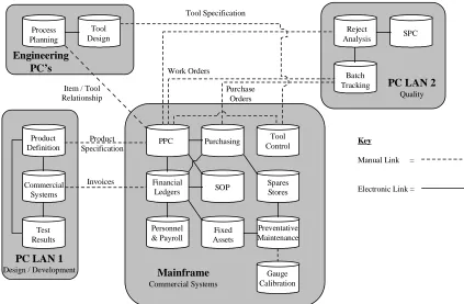
[image:21.595.115.538.446.723.2]Within the OE Division the implementation of MFG/PRO resulted in a comprehensive restructuring of the original information systems. The original system is illustrated in Figure 2 below, (Harrison et al 1995). It can be seen that the system was split into a variety of individual, standalone systems, linked manually, with a few electronic links between the key systems. These systems were designed and implemented separately, leading to poor integration and therefore, duplicated effort, (Harrison et al 1995).
Figure 2: Original Ferodo OE Division Information System
PPC Purchasing Tool Control Financial Ledgers SOP Spares Stores Personnel & Payroll Fixed Assets Preventative Maintenance Gauge Calibration Product Definition Commercial Systems Test Results Process Planning Tool Design Reject Analysis SPC Batch Tracking Work Orders Purchase Orders Tool Specification
Item / Tool Relationship
Product Specification
Invoices
Key
Manual Link =
Electronic Link =
Engineering PC’s
PC LAN 1
Design / Development
PC LAN 2
Quality
Mainframe
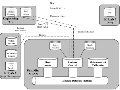
As a result of implementing MFG/PRO the information systems were rationalised considerably. The result was to have a core system serving a number of sub-systems. The sub-systems were all selected as they were relatively independent and as such they did not need to be linked to the core system. The structure of the new system is reflected in Figure 3 below, adapted from Harrison et al, (1995).
Figure 3: New Ferodo OE Division Information System
Product Definition Commercial Systems Test Results SPC Key
Manual Link =
Electronic Link = Process Planning Tool Design Engineering PC’s
PC LAN 1
Design / Development
PC LAN 2
Quality Batch Tracking Unix Mini & LAN Reject Analysis Tool Specification Item / Tool
Relationship Product Specification Invoices Fixed Assets Business Control Maintenance & Calibration
Common Database Platform
1.4
The MRPII Software Package used – MFG/PRO
In keeping with many other MPC Packages, for example SAP and J.D.Edwards, MFG/PRO is an integrated MRPII system that consists of a number of fully interactive modules to assist with control of many parts of the business.
Reading the software brochures and Web-Site information, (Minerva Industrial Systems Web-Site, SAP Web-Site1), these packages have many impressive features, including:
• Supply chain management;
• Shop floor data capture;
• Sales, purchasing and distribution order processing;
• Financial management;
• Integrated manufacturing.
These packages support a range of company types, (Wortman et al 1996). For example Minerva has case-studies for a number of installations: Courtaulds Chemicals; Kitchen Range Foods; Varity Perkins and Hubbard Group Services, (Minerva Industrial Systems Web-Site).
The systems are based on large relational databases, written using modern fourth generation languages. For example MFG/PRO was developed using a language called Progress. A fourth generation language can be defined as a modern programming language that appears similar to human language, (Webopedia 2000).
1
1.5
Statement of the Area of Concern
Significant effort has been focussed on the implementation of Manufacturing Planning and Control systems. This has helped systems implementers determine the best way to go about an implementation – for example the ‘Proven Path’ methodology for implementing MRPII systems first proposed in the 1970’s, (the Proven Path implementation methodology is detailed in section 2.3).
Established theory does not, however, fully explain how to develop an existing implementation. Chapter 2 will show that there has been work done on how to use Linear Goal Programming to determine which of a number of potential development projects should be done so as to maximise the potential return whilst minimising the risk. Chapter 2 will also show case studies of development activities. The development options available to a systems development team have not been so well defined, neither has the best practice to be adopted when selecting an option. As a result of identifying the potential gains to be made in this area, the post implementation development of MPC systems was defined at the start of the PhD research as the area of concern.
1.6
Objectives of the Research
Due to the research being industrially based the research objectives must combine an element of contribution to the collaborating company as well as working towards satisfactory research output. To this end the original aims of the project were formally defined as below:
• To review the existing information systems within Ferodo;
• To review the nature of change of these information systems;
• To devise a strategy for development of a company wide information system;
• To implement the strategy within the limits of time available;
• To therefore devise a methodology for the development of business systems.
The hypothesis that was formed was as follows:
• It is possible to define a methodology for the structured, post implementation,
development of MPC systems.
In order to achieve the aims and prove or disprove the hypothesis the following detailed objectives were set:
• A detailed understanding of MPC systems was to be gained, from literature review
and case-study visits;
• A detailed understanding of the Ferodo MPC systems was to be gained;
• The Ferodo MPC systems were to be developed to increase their effectivity;
• The understanding of MPC systems development gained during the Ferodo
development was to be used to devise a methodology for MPC systems development;
• The methodology was to be tested using appropriate techniques in order to help verify
1.7
Research Framework
There are two types of research framework that could be applied to a research project, (Saunders et al 2000):
• Theoretical Framework;
• Conceptual Framework.
A theoretical framework is usually determined at the start of a research project and consists of a researcher utilising existing theory when conducting the research. For this approach to be successful the theory must exist in advance, allowing the researcher to test and expand the existing theory. The main drawback of this approach is that establishing a theoretical framework prior to conducting research could potentially put boundaries on the research. The researcher may have difficulty conducting research if the participants in a research project have views that deviate excessively from the theoretical boundaries. In addition the boundaries may themselves bring the research to an artificial end as they may limit the expansion of the research, (Saunders et al 2000).
As an alternative a researcher may decide not to establish a theoretical framework at the start of a research project but to start to conduct research and collect data. The researcher can then analyse the data collected and determine how the research should proceed based upon the findings. This approach to research, establishing a conceptual framework, has the following characteristics, (Saunders et al 2000):
• The approach is inductive in nature;
• Data collection determines the research path;
The research objectives detailed in section 1.6 required the researcher to be an active participant in a systems development activity and to formulate the research output as a result of this interaction. As a result of this requirement a conceptual framework approach was adopted.
As explained in section 1.5 the research was to be undertaken into the post implementation development of MPC systems. Authors such as Thomas Wallace, (Wallace 1990) and Oliver Wight, (Wight 1984), demonstrated how to successfully implement these systems. Harrison et al, (1995), present a case study of a post implementation development project. Reynolds et al, (1997), present a methodology, using Linear Goal Programming, that helps a systems developer decide which development projects would offer the greatest return with the lowest risk. Following on from the work presented by these authors the aim of this research was to formalise the systems development process. The work was to be conducted in a manufacturing company using an MRPII system and the research findings would be restricted to this subset of company. The research was conducted as below.
Using knowledge gained during the literature review presented in Chapter 2 the author conducted a number of systems development projects within the case study company. Once these projects were completed the author was able to reflect upon these projects and develop a methodology for systems development.
1.8
Research Methodology
There are three main approaches to research, (Saunders et al 2000):
• Experimentation, (physical or theoretical interaction with a subject);
• Survey, (soliciting opinion regarding a subject);
• Case Study, (reviewing the work of others in real-life situations).
The experimentation approach can be further broken down as follows:
• Conceptual Study, (theoretical analysis of a subject);
• Mathematical Modelling, (attempt to prove or disprove a theory mathematically);
• Laboratory Experiment, (controlled experimentation in a laboratory environment);
• Field Experiment, (experimentation in a real-life environment);
• Action Research, (participation in a real-life situation, reflecting on the findings).
The author was registered on a Total Technology PhD which was to be based on-site within a collaborating company. The research required the author to gain an understanding of the approaches that could be used to develop an MPC system and determine a methodology to structure and control the application of these approaches. For this reason only the following research methodologies could be applied:
• Survey;
• Case Study;
• Field Experiment;
Field Experimentation requires the researcher to repeat experiments to verify results. Industrial projects cannot be repeated and as a result this methodology was also rejected.
As the project was based in an Industrial environment and addressed issues relevant to industry, it was clear that the Action Research methodology should be considered.
Action Research has been around since the 1950’s. One of the earlier authors to define the concept of Action Research was Blum, (1955). Blum described Action Research as having two stages, a diagnostic stage where a situation is reviewed in order to develop theories and a practice stage where the theories are put to the test.
Work on Action Research has been developing at the University of Lancaster, from where there have been a number of published works. Several of the better known works on Action Research were published by Professor Peter Checkland, (Checkland 1981, 1991, Checkland and Scholes 1990, Checkland and Holwell 1998), though there are other authors writing in the field, (Baskerville and Wood-Harper 1996, Wilson 1990).
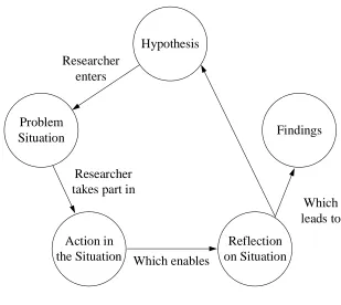
The Action Research cycle proposed by Blum has been developed since the 1970’s to include up to five stages, (Baskerville and Wood-Harper 1996). The new stages allow for results to be developed from testing the theory initially developed and the theory either proved or developed into a new theory. This new theory then re-enters the Action Research cycle if the situation permits.
Figure 4: The Action Research Cycle
Hypothesis
Action in the Situation
Reflection on Situation Problem
Situation Findings
Researcher enters
Researcher takes part in
Which enables
Which leads to
The Action Researcher, therefore, interacts with a company, creating and testing theories by undertaking projects in the company, (Baskerville and Wood-Harper 1996).
Baskerville and Wood-Harper, (1996), present a number of criticisms that have been levelled at the Action Research methodology:
1. It is difficult for researchers to remain impartial when researching within a company; 2. There can be a lack of scientific discipline when working with companies;
3. Action Research projects occur in unique situations, which are usually unrepeatable.
This approach addresses the main criticism of the Action Research methodology, (difficulty in remaining impartial) but does have drawbacks itself. One criticism is also the strength of the approach, the researcher is an observer of the situation. Research output is still generated but the researcher may not develop general skills.
Another criticism of Case Study research is that it would appear to be difficult, as an observer, to gain a detailed understanding of the operation of the problem situation.
Researchers are also often teachers, skills must be learned before they can be passed on and Case Study research would not appear to support this.
As described in section 1.2 the Total Technology Scheme is an attempt to generate research output by being directly involved in solving problems faced by industry. The purpose of this is to provide a practical and general education to a researcher.
The Total Technology Scheme as applied to industry based research would, therefore, appear not just to lend itself to the Action Research cycle but to actually require application of the Action Research cycle in order to furnish the researcher with both a practical and an academic education. Drawbacks of the scheme are addressed by directly involving University and Industrial staff in a collaborative project and assisting objectivity by providing objective assistance to the researcher.
1.9
Organisation of the Remainder of the Study
The thesis is organised into 5 main chapters. Following on from this chapter, Chapter 2 will outline some of the MPC philosophies in current use, providing greater detail on Manufacturing Resource Planning, as this is the technique used by the collaborating company. Chapter 2 will also outline the development of computer technology before describing some Systems Analysis and Design methodologies. Chapter 2 will end by discussing the findings of an investigation into documentation techniques and protocols.
Chapter 3 will then explain the development of quality systems within the collaborating company and propose a methodology for structured MPC systems development. It will continue by showing that documentation is of concern to manufacturing companies and will explain the development of a documentation system for the collaborating company. The methodology will be expanded to include the systematic control and maintenance of MPC system documentation.
Chapter 4 will then present the results of applications of the methodology and structured interviews carried out to help validate the methodologies presented in Chapter 3.
Chapter 5 will finally discuss the work presented and will draw conclusions, before suggesting further work.
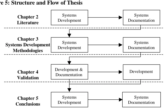
There are two main themes to the work contained within this thesis:
• Structured Development of MPC Systems;
Excluding Chapter 4 each of the above chapters is broken down into systems development and systems documentation sections. In all cases the systems development discussion precedes the systems documentation discussion. The structure and flow of the thesis is illustrated by Figure 5 below.
Figure 5: Structure and Flow of Thesis
In addition to developing and documenting the quality systems, work was done supporting many other systems within the business and implementing standard modules within the planning and control function of the business. Consulting and case study work was also done with some other manufacturing companies. The companies visited use a range of planning and control methodologies and all but one are either companies within the same group as the collaborating company or raw material suppliers to the collaborating company. Section 3.1 describes the companies visited or worked with.
The project plan for this research was developed to allow extra time to undertake this work which provided a general understanding of business operation. This is in keeping with the aims of Total Technology, (see section 1.2).
Chapter 2.
Manufacturing Planning and Control Systems
2.1
Introduction
Chapter 1 detailed the origins and background of the research. The chapter showed that the research would follow a conceptual framework as the experimentation and literature search findings would be used to guide the research to a satisfactory conclusion. This chapter will start to provide this framework by providing a detailed literature review.
Chapter 2 will start by introducing some early Manufacturing Planning and Control, (MPC), systems, (section 2.2), and will then discuss the development of Manufacturing Resource Planning, one of the main MPC systems in use today, (section 2.3). Following this there will be a discussion of some of the problems found when using these systems and solutions that have been suggested, (sections 2.4 and 2.5). There are some alternatives to this approach, however, such as Just in Time and Optimised Production Technology and these approaches will also be detailed, (sections 2.6 and 2.7).
2.2
Early Manufacturing Planning and Control Systems
A Manufacturing Planning and Control, (MPC), System can be defined as a system that ‘Provides information to efficiently manage the flow of materials, effectively utilise people and equipment, co-ordinate internal activities with those of suppliers, and
communicate with customers about market requirements’, (Vollmann et al 1997).
These systems, therefore assist businesses to control their businesses and manage the complex task of co-ordinating supply with demand with limited resources.
Work was developing on the systematic control of manufacturing organisations at the start of this century, notably F.W. Taylor developed the concept of scientific management using analytical techniques applied to the organisation of work, (George 1968). In the 1930’s these techniques were being applied to inventory management and techniques such as re-order point and the Economic Order Quantity formula, (a technique for determining an optimised production batch size), were developed.
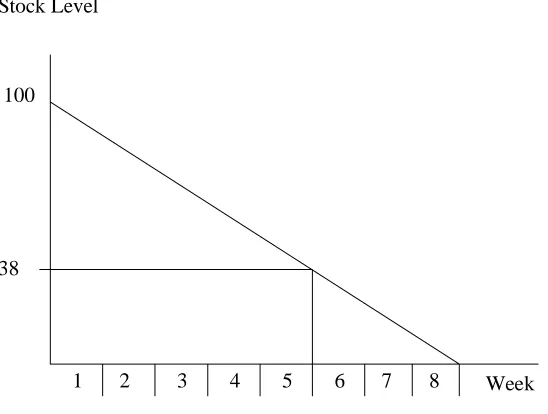
This technique relied upon using a series of receptacles to co-ordinate material supply. An alternative approach that was developed was the re-order point, (ROP), theory, (Vollmann et al 1997). ROP theory suggests that using the standard raw material purchasing time and average stock usage figures it is possible to determine the minimum stock level at which new material should be ordered. This is shown in Figure 6 below.
Figure 6: Re-Order Point Theory
100
38
1 2 3 4 5 6 7 8
Stock Level
Week
The strength of ROP is the simplicity of its application. There is a major weakness in that the ROP is calculated from historical consumption and takes no account of future consumption, either from forecast or actual customer demand. If the average usage was to increase then material would be ordered too late. This is illustrated in Figure 7 below where the stock is fully consumed sooner than expected and the raw material deliveries are over a week late. For this reason, an allowance, (Safety Stock), is generally applied to compensate for uncertainty in demand.
Figure 7: Effect of Increased Demand on Re-Order Point Theory
Approaches were needed that take account of future demand, either forecast or actual. During the second world war data analysis was being performed using a new technique – Operations Research, (George 1968). These techniques were applicable in manufacturing as concepts such as queuing and optimisation theory were being developed.
100
38
1 2 3 4 5 6 7 8
Stock Level
Week Planned Raw Material
Delivery Time Rate of Consumption
New Raw Material Requirement Time Point of Increased
In addition to stock control requirements there have also been significant changes in strategy in manufacturing companies in Britain since the 1970’s. During this time companies have been forced to look at mechanisms for improving product quality, costs and delivery performance. Conway, (1993), identifies a number of changes in the market that necessitate this strategy change:
• Competitive costs;
• Shorter lead-times;
• Reliability and quality;
• Increased flexibility;
• Increased product range;
• Innovation in process and product technology;
• Interesting jobs for staff.
To assist with facing these requirements companies have been forced to look at advanced MPC techniques which were developed from the Operations Research work carried out. There are any number of techniques that could be used by a company, or developed internally, to help with planning and controlling manufacturing activity. There are, however, a smaller number of well established techniques available.
2.3
Manufacturing Resource Planning, (MRPII)
Before any exploration of MRPII can begin it is important to first to define Material Requirements Planning, (MRP) and its development into MRPII. There is a lot of confusion about the difference between these terms, for example Kamenetzky, (1985), defines MRPII as Closed-Loop MRP which Wight, (1984), defines as a level below MRPII and Fox, (1983c), defines MRP as Manufacturing Resource Planning which is commonly understood to be MRPII.
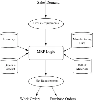
[image:39.595.178.476.391.718.2]Wight was one of the first authors to write about MRP and its development into MRPII so this thesis will use his definitions of MRP, Closed-Loop MRP and MRPII. The MRP cycle is represented in Figure 8 below, adapted from Orlicky, (1975).
Figure 8: MRP Logic
Inventory
Bill of Materials Orders +
Forecast
Manufacturing Data Gross Requirements
Net Requirements
MRP Logic Sales Demand
MRP is a push type manufacturing system. When an order is taken from a customer, or forecasted demand is input to the system, the system, either manually or computationally, will examine the item requested and determine whether it needs to be manufactured or bought in. The system then reviews stocks and scheduled receipts of the item to see if demand can be satisfied from current and future stock. If demand cannot be met in this way, the system will make sure that there are enough items bought or made in time for demand.
This is done by examining the Bill of Materials, (essentially the recipe for a product), to determine the components that make up the item. The system then reviews each of these components in turn and determines if there are stocks or whether they have to be made or purchased. The system explodes through the Bill of Materials until the basic components are defined.
At this point, the launch date for components, (either manufactured or purchased), is determined by using the lead-time. A lead-time is the time taken for a particular process or event to happen. The system will subtract this lead-time from the customer due date and make the new date the component launch date. If the component needs to be purchased, the supplier lead-time needs to be subtracted from the component due date to determine when the order should be released to the supplier.
Figure 9 below illustrates this procedure for a simplified Disc Brake Pad operation where a pad is made of a plate and some mix and the mix is made from a chemical. In this example 0.2 units of mix are used for every 1 plate and 1 unit of mix is made from 1 unit of chemical. It can be seen that there is a 2 week lead-time for the manufacture of both a disc brake pad and mix, a 2 week lead time for the purchase of plates and a 3 week lead-time for the purchase of chemicals. The Bill of Materials and item characteristics are shown in Figure 10 below. This example assumes no stocks, batch sizes equal to demand, no scrap and no scheduled receipts of components.
Figure 9: MRP Calculation for a Disk Brake Pad Product Structure
Week 1 2 3 4 5 6 7 8
Demand for Pad 500
Requirements for Plates 500
Post purchase order for Plates 500
Requirements for Mix 100
Requirements for Chemical 100
Post purchase order for Chemical 100
Figure 10: Sample Disc Brake Pad Bill of Materials
Disc Brake Pad
Manufacturing Lead-Time = 2 Weeks Mix (0.2 Units)
Manufacturing Lead-Time = 2 Weeks Chemical (1 Unit) Purchasing Lead-Time = 3 Weeks
Plate (1 Unit)
Purchasing Lead-Time = 2 Weeks
The cumulative lead-time, allowing for this factory to procure raw materials and manufacture a pad is, therefore, 6 weeks. If a quicker delivery is required then stocks must be held or some or all of the component lead-times compressed.
This example was of an extremely simple Bill of Materials. In some manufacturing situations the Bill of Materials can have thousands of components, where some are shared between different items.
In summary, in the MRP logic the following steps are taken:
Collect gross requirements for product;
Nett off stocks and scheduled receipts;
Apply lot sizes and safety stocks;
Offset for lead-times;
Explode down to components and start again.
Before computers were used to perform this cycle it was undertaken manually. Typically it took between six and thirteen weeks to do a complete MRP run depending on the company size, (Wight 1984).
Also, with developments in computer technology it is possible to set controls on MRP, such as minimum stock levels, order quantities and safety stocks. Safety stocks of finished items can help a company deal with poor due date performance by holding stocks on site as a ‘buffer’ against uncertainty, (Orlicky 1975).
There are a number of lot sizing rules and algorithms to help calculate the ‘ideal’ order quantities, (Swann 1986), many of which can be used within MRP, for example:
• Fixed Order Quantity;
• Economic Order Quantity, (EOQ);
• Lot for Lot;
• Period Order Quantity;
• Set : Run Ratio;
• Least Total Cost and Part Period Balancing.
One of the drawbacks of the MRP cycle is that once the Works and Purchase Orders have been released, (given to the factory or sent to the supplier), there is no control over them and no method for monitoring their progress. For this reason Closed-Loop MRP was developed, (Vollmann et al 1997).
Figure 11: Closed-Loop MRP
Sales and Operation Planning
Master Production Scheduling
Material Requirements Planning
Capacity Requirements Planning
Shop Floor Control
Purchasing Realistic?
YES NO
MRPII was then developed to address more drawbacks by adding finance and accounting options, Business Planning and Rough Cut Capacity Planning to Closed-Loop MRP, (Wallace 1990).
Figure 12: MRPII
Wight, (1984), summarised three benefits of an integrated MRPII system:
1. The financial and operating systems are the same so that the accounts are a reflection of actual operation;
2. The system can perform ‘what-if’ analyses. Rough Cut Capacity Planning, (a tool to help with doing this), will be explained in section 2.5;
3. Everyone in the company uses the same system and can see the effect of their work.
Business Planning
Sales and Operation Planning
Rough Cut Capacity Planning
Material Requirements Planning
Capacity Requirements Planning
Shop Floor Control
Purchasing Realistic?
YES NO
Each stage shown in Figure 12 above represents an operation in the business with feedback between each stage. The main stages are detailed below, (Wallace 1990):
Business Planning
This is the establishment of the top level, strategic, aims and goals of the business. These aims define the direction of the business and are expressed financially. The Chief Executive and senior staff are responsible for the Business Plan.
Sales and Operations Planning
This is the weekly or monthly process of planning the rate of factory output in terms of broad product families to meet short term goals. The sales and operations plan is developed to meet the requirements of the Business Plan.
Master Production Scheduling
This is the daily process of converting Sales Orders into top level Work Orders for the items sold by the Factory. The schedule must cover the total, or ‘cumulative’, lead-time for the factory to allow the MRP run to calculate achievable Purchase and Work Orders. In effect this de-couples supply and demand.
Material Requirements Planning
Capacity Requirements Planning
This is the stage whereby an attempt is made to link Work Orders with true manufacturing capacity. The system aggregates the total work content of each Work Order by machine or operation as defined in the routing and will predict how much capacity will be needed and when.
Shop Floor Control
This involves monitoring the actual work output of the Factory and the status of all Work Orders in the system by logging the status of each Work Order as its position in the factory changes.
Purchasing
This is the process whereby material requirements for manufacturing are met by negotiating purchase contracts using forecasts and actual demand as a guide to predict future consumption.
Due to the complexity of MRPII, systems are usually applied in the form of integrated databases of the type shown in section 1.4. Originally an MRPII database would have been written specially for an application, either on contract or in-house. More modern thinking, however, is that software should be bought in as a package rather than developed in house for the following reasons, (Cerveny and Scott 1989, Cashmore and Lyall 1991):
• There are a wide range of different packages available on the market;
• It is quicker and cheaper to buy software as a package;
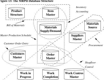
Many authors have publicly acknowledged the significance of the MRPII database. Schonberger, (1984) and Kamenetzky, (1985), both state that one of the biggest contributions of the MRPII philosophy is the structured manufacturing database. Figure 13 below, adapted from Hussain and Hussain, (1995), shows a very simplified MRPII database structure.
Figure 13: The MRPII Database Structure
Product Structure Order Master Customers Master Work Centres Master Work Completion Work in Progress Materials Supply/Demand Item Master Materials Source Suppliers Master Shopfloor Control Procurement Customer Order Entry
Bill of Materials
Master Production Schedule
Inventory Accounting
Figure 13 above shows six typical sections or ‘modules’ within an MRPII package: 1. Bill of Materials, (the product structure);
2. Master Production Schedule, (the sequence of work for manufacture and purchase); 3. Customer Order Entry, (the mechanism for entering and reflecting demand);
4. Inventory Accounting, (stock reporting and reconciling for financial measure); 5. Procurement, (purchasing and contract negotiations);
These modules are themselves split into ten datafiles containing either static or dynamic data as below:
1. Product Structure, (a Bill of Materials or recipe for manufacturing detailed by item); 2. Item Master, (a list of all items and components used, or worked on, in the factory); 3. Materials Supply/Demand, (a breakdown, by part, of current inventory);
4. Customers Master, (a list of customers);
5. Order Master, (a list of orders on the factory, split by customer);
6. Work in Progress, (a detailed list of all incomplete Work Orders in the factory); 7. Work Completions, (a detailed list of all complete Work Orders);
8. Work Centre Master, (a list of the work centres and processing times by item); 9. Suppliers Master, (a list of suppliers);
10.Materials Source, (a list of the supplier for each material and contract details).
Because the MRPII database structure consists of a number of interlinking modules, rather than one extremely large datafile, it is possible for the same structure to be used in a variety of companies. It is not necessary for these companies to all use the software in the same way, as there are many ways each module can be used, (Orlicky 1975).
To assist with defining exactly what constitutes a successful implementation, Wallace, (1990), describes a classification system with class A being the best and class D being the worst. The different classes of MRPII users can be defined generally as below:
Class D;
A class D implementation could be considered to be a failure to successfully implement and operate an MRPII package with none of the improvements shown in class C below.
Class C;
A class C company will show a reduction in inventories and will have a better ability to process engineering changes. The business would still operate as it used to but will show a very good return on investment.
Class B;
A class B company, in addition to the reduction in inventories and ability to process engineering changes from class C, will also have a dramatic improvement in the ability to deliver on time, will have minimised component shortages in the factory and will have reduced the need to work unplanned overtime.
Class A.
The above criteria are by no means complete; there is a list of 35 questions posed by the Oliver Wight company before the classification is made and the answers are graded based on the number of questions to which a company gives the answer ‘no’ as below, (Wallace 1990):
0-3 questions answered negative - class A; 4-7 questions answered negative - class B; 8-10 questions answered negative - class C; 11-14 questions answered negative - class D.
The results of a survey into MRPII users showed that only half of all MRPII users were happy with newly installed systems, (Wilson et al 1994). In the same paper the authors state that only 9% of companies surveyed would actually classify themselves as ‘class A’ but that these companies showed a 200% return on investment. This figure is made more significant by the fact that the average spending on implementing MRPII packages varies little across classes A to D, (Wilson et al 1994).
A number of authors have claimed that a successful MRPII implementation need not use all the MRPII modules, system requirements depend on the situation being addressed, (Petty and Harrison 1995, Ang et al 1994). This would appear to conflict with the ABCD classification system which asks questions such as, (Wallace 1990):
• Does the company employ a forecasting system?
• Is there a capacity planning system?
Orlicky, (1975), defines three functions that an MRPII package should cover once successfully implemented and sub-divides these functions. This list does appear simplistic but would appear to provide a basis for addressing some of the operational issues that will be faced when implementing a system:
1 Inventory;
1.1 Order the right part; 1.2 Order the correct quantity; 1.3 Order at the right time.
2 Priorities;
2.1 Order with the correct due date; 2.2 Keep the due date valid.
3 Capacity.
3.1 Provide a complete load to the factory;
3.2 Provide a valid, manageable load to the factory;
3.3 Provide factory personnel with sufficient forward visibility.
In addition to operational issues, Wight defined 6 principles and philosophy changes that management should instil in a company when implementing MRPII, (Wight 1984): 1. Define the objectives of the system;
2. Assign accountability for each part of the system;
3. Develop understanding of the system through education and training; 4. Provide the correct tools for staff to perform their jobs;
Wight also defines the role of the Chief Executive in an MRPII implementation and the subsequent use of the package. When the package is being implemented, the role of the Chief Executive is to appoint a project team, to support them and to arbitrate but not to interfere. Once the package is in place the Chief Executive should assume responsibility for:
• The sales and operations plan;
• The production planning policy;
• Installing teamwork initiatives.
Key points when implementing packages have been forwarded by a number of authors. The most prominent piece of advice is to implement in stages either top down or in a modular fashion, (Petty and Harrison 1995, Ang et al 1994, Carrie and Banerjee 1984). Even the ‘Proven Path’ supports this method, allowing the financial modules to be implemented last, effectively creating a Closed-Loop MRP system before an MRPII system, (Wilson et al 1994).
This section has explained the operation of the MRPII system, which has proved to be an extremely popular system in the western world. This success has been attributed by Segerstedt, (1996), to the following attributes of an MRPII system:
• MRP considers future demand when calculating material requirements where as
traditional approaches look at historical demand;
• MRP allows for components to be changed for an item and will recalculate future
material requirements. This cannot be inferred from historical demand patterns;
• MRP allows for definition of a forecast based on historical demand and market
There are, however, some problems with the MRP philosophy. Section 2.4 will look at some of the problems found and some solutions proposed.
2.4
Problems with MRPII Systems
At the start of section 2.3 the apparent confusion over the terminology of MRPII was illustrated. Dwyer, (1995), shows that despite the definitions of the system, many users are confused over the actual workings of MRP, Closed-Loop MRP and MRPII. There is only one solution to both these issues; education and training for all staff. Wilson et al, (1994), state that 80% of users need training before starting to use a system, (called ‘going live’). It is apparent from experience of these systems, though, that no implementer should be satisfied with anything less than 100% of users educated before going live as skills are needed to address ‘teething problems’.
In the early days of MRPII implementation, implementers were simply computerising the existing system, (Bodington 1995). This is in keeping with the data processing era proposed as the first of three computing eras in section 2.9. As a result of this the systems were likely to yield no benefits and to be considered failures, (Bodington 1995).
An examination of methods available to ensure data accuracy must start before the implementation. Section 2.3 showed that commitment to an implementation is needed from senior management and that education is required for all staff, (a theme that continued into this section). These points illustrate that responsibility for the accuracy and therefore, the usefulness of an MRPII system rests with the users and not just with the implementation team. Dwyer, (1995), quotes an MRPII software supplier as saying that less of a system’s success is the result of the software chosen than can be directly attributed to the people using and implementing the software. This illustrates that the choice of software may not necessarily be a crucial step in the implementation of an MRPII package. It is difficult to understand how this conclusion may have been reached.
Once a package is chosen and education provided it is time to implement the system. Section 2.3 showed that the most popular implementation method used was the Proven Path. Statistics have shown that many implementations fail, including Proven Path implementations, (Ang et al 1994, Blood 1992), in these cases failure means not fully achieving the aims and objectives of the implementation.
To help avoid a failed implementation it may be necessary to consider not implementing an entire MRPII package, or to implement in stages by addressing modules individually, as shown in section 2.3.
Once a package is implemented it is important to measure performance properly. In this case performance is not just of the package but also of the users. Neely, (1997), argues that in order to control the business effectively it is vital that performance measures be developed that actually reflect true performance against the strategic plans. It is important that performance measures are used to encourage staff to work towards strategic targets, such as schedule adherence. This was mentioned in section 2.3.
So far all the problems found with an MRPII package have been related to the use of the package and not with the package itself. Though significant effort can be put into addressing these problems there are some problems that some companies experience that are a function of the basic philosophy of MRPII.
Porter and Little, (1996), Kamenetzky, (1985) and Swann, (1986), discuss several problems as a result of the assumptions of the MRPII philosophy:
• MRP plans are based on infinite capacity calculations;
• MRP assumes static batch sizes;
• MRP assumes standard lead-times;
• MRP assumes standard queue sizes;
Infinite Capacity.
When MRP performs its calculations it derives Work Order requirements from the Master Production Schedule. What MRP does not consider is whether or not there is sufficient capacity in the factory to process the Work Orders. There are several techniques, from the simple to the sophisticated, available to address this problem. As a result of the breadth of this area a full analysis is undertaken in Section 2.5.
Static Batch Sizes
An MRP system cannot calculate transfer batches. Transfer batches allow some of a batch to be taken to the next stage in the process before the entire batch is complete to speed up the flow of materials through the factory.
Standard Lead-Times
An MRP package cannot alter the lead-times to reflect a true prioritisation sequence through a factory. This could result in components being launched into a factory to an incorrect order start date if the process is changing or if the Work Order in question is being rushed through the factory and skipping some of the queuing time.
Standard Queue Sizes
Traditionally a queue of work sits in front of each machine waiting its turn for processing. This work is called the Work in Process, (WIP). One way to speed up order progress through a factory is to change the queue size which will reduce the lead-time. MRP cannot do this automatically, as lead-times, (and therefore, queue sizes), are fixed.
Fixed Routing
Swann, (1986), comments on these drawbacks and examines solutions. The mechanism he suggests is nothing more than human control. Swann’s solutions involve monitoring and planning carefully so that overloads do not happen in the factory and manually manipulating queues and batch sizes to allow for urgent Work Orders. This solution corroborates the work of Dwyer, (1995), as presented in section 2.3, which showed that a system’s success was about the people and the way they use it. The overriding message is that the users must think of an MRPII system as more than a piece of software but rather as a tool that requires human interaction. As a result, MRPII cannot act as a substitute for management.
There are, however, two technologies available that address the above issues, (these solutions are reviewed in section 2.5 and section 2.7, respectively):
• Finite Capacity Scheduling, (FCS);
• Optimised Production Technology, (which is in fact a specialised form of FCS).
It is also apparent that implementers sometimes forget that when implementing MRPII there are several other tools available for use. Dwyer, (1995) and Golhar and Stamm, (1991), argue that the concepts of Just in Time, (an alternative to MRPII), can be applied in conjunction with MRPII. These authors suggest that the implementation of MRPII systems is not simply the installation of a package but the analysis and systematic improvement of the manufacturing organisation.