TIME BASE FIRING PULSE DELAY CONTROL FOR IMPROVING
SINGLE PHASE INDUCTION MOTOR SPEED PERFORMANCE
USING FUZZY LOGIC CONTROL
Dirman Hanafi1, MohdAzkar Sidik2, Mirza Zoni3, Hidayat4
1,2Advanced Mechatronic Research Group (ADMIRE), Faculty of Electrical and Electronic Engineering,
UniversitiTun Hussein Onn Malaysia, BatuPahat, Johor, Malaysia
3,4Electrical Engineering Department, Faculty of Industrial Technology,
Universitas Bung Hatta, Padang, Indonesia E-Mail: [email protected]
ABSTRACT
This paper focuses on the fuzzy logic controller design for improving the single phase induction motor speed control performance. The controller strategy is done through phase angle control method. The phase angle is controlled by controlling the time base firing pulse angle delay of the triac. Based on experimental results, the fuzzy logic controller is a suitable controller to improve the single phase induction motor speed because it able to reduce the rise time, settling time, peak time and overshoot response to 0.10s, 0.17s, 0.29s and 0.09 % OS respectively. Then compares with the Proportional Integral Derivative (PID) controller responses, the fuzzy logic controller responses are better with the rise time (Tr), the settling time (Ts), the peak time (Tp) and the overshoot (% OS) are 0.08s, 0.08s, 0.05s and 0.004% smaller than PID controller.
Keywords: Single phase induction motor speed control Fuzzy logic controller Time base firing pulse delay
INTRODUCTION
Single phase A.C supply plays important roles in electrical usage because it is commonly used for general electrical purpose in domestic or commercial applications where three phase power supply is not available. Based on this supply, single phase induction motors become one of the most widely used for numerous domestic and industrial applications like home appliances, industrial control system, and automation because of their it offer lower maintenance, reliable and smaller motor size. Single phase induction motor has been covered most servo application in robotics, machine tools and positioning devices.
Normally, it has two winding, main and auxiliary.An auxiliary winding has more turns than main winding (Yo, 2000). Traditional single phase induction motor run directly from AC voltage supply at one speed only. The improvement in ac motor control enable the speed of single phase induction motor to be run on variable speed, which can reduce power consumption, acoustic noise and mechanical vibration. The critical aspect in AC motoris the role of the researcher or engineer to control the speed of an AC motor that being used. Traditionally, the AC motor is controlled by two classical strategies, vector control and torque control. Vector control and direct torque control are the two classical strategies to control synchronization and asynchronous of induction motor (Shenand Dai, 2010).
As mantion previous, the single phase induction motor is widely use in our daily application because of their ability to operate from a single phase power supply.
Since it is impossible to reliably operate at unstable range, simple voltage control (open loop control) is limited to controlling in a narrow range. The speed of the single phase AC induction motor can be adjusted either by applying the proper supply voltage amplitude and frequency (called volts per hertz) or by the changing of supply voltage amplitude with constant frequency (slip control) (Stekl, 2003). To make it is possible to operate reliably even in the unstable range, it is necessary to detect the rotational speed of the motor and use a voltage control mechanism (closed loop control) that reduces the speed error when compared to a set value (Shirataha, 2015).
The speed of induction motor can be control by controlling the voltage applied to the stator voltage. With the enhanced technology in power electronics, a number of semiconductor devices have been introduced in voltage control application. The use of solid state components like the triac for the control of ac drives have been widely used in recent years for several industrial and home applications (Emenike, et. al., 2011). The voltage applied to the stator winding of the single phase induction motor can be control to achieve the desired speed by controlling the firing angle of the triac that are used in this work.
de ra Tr co in w in to ad sy of re th co ap R co pr th A so so im Lo th us si lo fu pe Br Fi re pr th tra ov le m th co w fu de of us th pe T us to
evice which co ather than the
riac is connect ontrolling the nduction motor with less power
Mostly ntelligent contr o the firing ang
dvancement o ystem to contro f the traditiona esults when loa he artificial inte ontroller has s pplication (Raj
RELATED WO
Obayed ontroller using rogrammable hrough AC mot Altera Quartus
oftware. The oftware.
Dongal mplementation ogic strategies hree phase indu sed in this wo mulated using ogic control pro Moham uzzy logic con ermanent mag
ridge. The fuz ield Programm esponses are
roportional-inte he PI controll
ansition betwe vershoot and h ess oscillation, means performa han PI controlle Mallesh ontroller to co which is for DC
uzzy logic con erivatives and f the fuzzy lo sing the MAT he proposed co erformance of t
RIAC
The tri sually use for a o control the
onduct based o supply voltag ted in series w
gate pulse of r is controlled consumption ( y, for closed lo rol techniques gle circuit (Em f the technolo ol the inductio al controllers d ading variation elligent (AI) te shown high po
aji and Kumar
ORKS
det. al. (2009 g VHDL for logic array (F tor. Then, the s 2 version
controller is a
leet. al. of the control s. The control uction motor. T ork is mamda
Matlab softwa oduced better p med Ramadene ntroller (FLC)
net DC motor zzy logic cont mable Gate Ar compared egral (PI) cont er performanc een the require higher rise tim , zeros oversh ances of the fu
er.
ham(2007) a ontrol the spee C motor and A ntroller is desig integral fuzzy ogic controller TLAB Simulink ontroller able t
the electric ma
iac is a power ac switching ap
current flow
on the gate pu e (Chee-Hoe, with the motor, the Triac, the d smoothly an (Kumar, et. al., oop system, co were used to p menike, et. al.,
ogy, the use on motor is req does not give th n condition. In echnique, such otential for ind r, 2008).
9) developed a r implementa FPGA) to co controller is si 9.0 software able implemen
(2012) pre ller based on P llers are appli The fuzzy logi ani. The two c are. The result performance.
et. al. (2014) to control th r via a config troller is imple rray (FPGA) c with the troller. The res ces in the lac ed speed and me. For the FL
hoot and less uzzy logic cont
applied the ed of the elect AC motor. In gned based on reasoning. Th
is evaluated k and the resu o improve the achine.
r electronics d pplications bec w over both
ulses it receive et. al., 2013). and hence by e speed of the nd effectively , 2013). onventional or
provide signal 2011). As the of intelligent quired because he satisfactory n recent years, as fuzzy logic duction motor
a fuzzy logic ation of field ontrol position imulated using and Matlab nted using two
esented the PID and Fuzzy ied to control ic control type controllers are ts shows fuzzy
proposed the he speed of a guration of H-emented using circuit and the conventional sults show that ck of smooth the present of LC controller, rise time. It troller is better
fuzzy logic trical machine this work, the n proportional, e performance by simulating ult shows that speed control
device that are cause it ability halves of an e . y e y r l e t e y , c r c d n g b o e y l e e y e a -g e l t h f , t r c e e , e g t l e y n alternatin especiall triac con impleme applicati
used to c alternatin utilizatio power ap Figure-1 F dimmers is driven reducing Guy, 200 PID CO controlle and it i (Hanafi, principle processe The obje changing block dia F measurem and deri control o three par on the a the futur of the co
ng cycle. Sev y single phase ntrol still rema
nting spe ons(Emenike, The main adv control the curr ng waveform on. However th
pplications wh shows the tria
Figure-1. Triac
The triac app through to var n to change the g the speed by
05).
NTROLLER
The most er design is Pro
s most widely 2010). It is a c e of PID cont d measured va ective of the co g the inputs o agram is shown
Figure-2. Bloc
There are 3 ment which ar ivative. The c of a motor is c rts in which P
ccumulation o re error based ntrol system is
. .
veral scheme e motors are a ins a cheap an eed contro et. al, 2011). vantage of triac rrent switching
and allows he triac is not s here the switch ac symbol for c
c symbol for ci
plications are rious forms of e trigger phase reducing RMS
commonly u oportional-Inte y used contro closed loop co troller is don alue and the de ontroller is to m of the system.
n by Figure-2.
ck diagram of P
parameters fo re called the control mecha ontributed by value depend of the previous on current rat s given by
. .
s of motor available howe nd an easy me ol for
c is the device g on both halve much better suitable for som hing is more d circuit diagram
rcuit diagram.
ranging from AC control. T angle for ac v S voltage (Grov
used algorithm egral Derivativ
oller in the i ontroller. The w
e by calculati esired reference
minimize the e The PID Co
PID controller
or the PID co proportional, i anism such as the summation upon current s error and D e change. The
control ever the ethod of many can be es of an power me high difficult. . m light he triac voltage, ver and m for e (PID) ndustry working ing the e point. error by ontroller ontroller integral s speed n of the
error; I predict e output
in Ta fa in m el FU Lo ef in 20 in de de th Th co lo Fi (L of us dy in co co SI de sin co A sin lo th Th Based ncreasing param
able 1. PID c ast reaction on ncrease in con mode) and suit liminate oscilla
UZZY LOGIC
[image:3.612.322.536.131.204.2]Fuzzy otfiZadeh in 1 fficient contro ndependent of 012). It has fou nference mec efuzzification ( Fuzzy eveloped by c he fuzzy logic his type of in ontrol problem ogical and m igure-3 shows Liu and Abony
Figure-3. A
Genera ften the most sually require ynamics. This ntuitive unders
ould come from omputer simula
ISTEM DESI
In this esigned to im
ngle phase in ontroller contro
A. System Arc
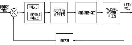
Figure-ngle phase in ogic controller. he reference sp
he input of the
on the equa meters KP, KI ontroller has a change of the ntrol signal to table action in ations (P mode
C CONTROL
Logic was pro 965. The fuzzy oller as it ha
plant model ( ur main compo chanism, the (Passino, and Y
logic contro ombining the and real wor ntelligent cont ms via more acc mathematical
s a typical fuz i, 2005).
A typical fuzzy
ating the rules difficult step s some exper knowledge c tanding gained m a plant mo ation (Hanafi, 2
GN
s work, the mprove the spe nduction moto
olled the firing
chitecture
-4 illustrates duction motor The actual m peed of the sin e fuzzy logic c
ation above, and KD can b all the necessa e controller inp lead error to nside control ) (Rao and Mis
L
oposed for the y logic control andles non lin
(Satyanarayana onents, they are e fuzzificatio Yurkovich, 199 ol is easily
theoretical inf rld based cont trol systems a curate, effectiv
approaches ( zzy control sy
y control system
for fuzzy con p in the desig rt knowledge could be in th
d from experi del which is t 2013).
fuzzy logic eed control pe r (SPIM). Th pulse delay (α
the overall s r speed contro otor speed is c ngle phase ind controller is the
the effect of be explained in ary dynamics: put (D mode), wards zero (I error area to shra, 2014).
e first time by ller is the most nearity and it a and Srujana, e rule base, the on and the
98).
designed and frastructure of trol problems. allows solving ve and efficient (Kose, 2012). ystem schema
m schema.
ntrol system is gn process. It of the plant he form of an menting, or it then used in a
controller is erformance of he fuzzy logic α) of the triac.
system of the ol using fuzzy compared with duction motor. e error (e) and f n : , I o y t t , e e d f . g t . a s t t n t a s f c e y h . d
change o controlle Reference Speed +‐ Figu induction B. Desi Base compose Fuzzifica Defuzzif 1.
for this p (ce). The error (e) the refer motor (ω of error by provi single p change o the previ the chang (2) (3) 2. fuzzifica members change o following Linguist Value Negative Negative Medium Negative Small Zero Positive
of error (ce) a er is the time ba
Error (e)
Change of Error (ce)
ure-4. Block d
n motor speed
ign of Fuzzy L
ed on Figure ed based on
ation, Rule B fication.
Define input a The input var purpose are th e output variab variable is det rence speed (ω ω_act ). The ch
variable contr iding the info phase inductio of error (ce) is m
ious error and ge of error (ce)
Membership F The second st ation process to
ship for linguis The fuzzy se of error and firi
[image:3.612.81.290.396.487.2]g table.
Table-1
tic Notati
e Big NB
e NM
e NS
Z PS
and the outpu ase firing pulse
Fuzzy Logic Controller Triac
Feedback
diagram overall control using f
Logic Controll
-3, the fuzzy n 4 elemen
ase, Fuzzy In
and output vari riables of the f he error (e) and ble is the firing
termined by th ω_ref )and the ange of error ( ributes to the ormation abou nmotor speed measured by th
the current err ) are given by:
1
Function and L tep in the fuzz o convert crisp stic terms of fu ets and lingui ing angle delay
1. Input variable
ion Range [2000 -1500 -10 [1500 -500] [-1000 -5
[-500 0 5 [0 500 10
ut of the fuzzy e delay (α).
Firing Pulse
Single Phas Induction Motor
l the single pha fuzzy logic con
ler
y logic contro nts which ar nference Syste
ables fuzzy logic co d the change o g pulse delay ( he difference b e actual speed (ce) or the rate inference mec ut the change d. The value he difference b ror. The error
Linguistic Varia zy logic contro p input into de uzzy sets.
stic terms for y are elaborate
e error.
MF
2000
-000] Trap
1000 - Trian
500 0] Trian
500] Trian 000]] Trian y logic se Motor Speed ase ntroller. oller is re the em and ontroller of error (α). The between d of the
change chanism of the of the between (e) and ables ol is the egree of
r error, d in the
pezoidal
ngular
ngular
[image:3.612.311.544.630.745.2]Sm Po M Po
L V
N
N M N Sm Ze Po Po M Po
L V
Po Po M Po Sm Ze
N Sm N M N
in ou de
c
N
N
N
Z mall ositive Medium
ositive Big
Table-inguistic Value
Negative Big
Negative Medium Negative
mall ero
ositive Small ositive Medium
ositive Big
Table-3.
inguistic Value
ositive Big ositive Medium ositive mall ero
Negative mall Negative Medium Negative Big
3. Rule B Rule b nference proce utput. The tab evelop in this w
Table-4. Tria
e
ce NB
NB NB
NM NB
NS NM
Z NM
PM [5 15 PB [1 20
-2. Input variab
Notation R
NB [-1 NM
[-3 NS
Z [-PS [0 PM [3 1 PB [7
1
. Output variab
Notation R
PB [0 PM [0 0 PS [0
0 Z [0
0 NS [0
0 NM [0
0 NB [0
0
ase for the fuz based is a set ess to evaluate bulation of the works are as in
angular membe varia
NM NS
NB NM NM NM NM NS NS NS
500 1000 500]
1000 1500 000 2000]
ble change of e
Range
1500 1500 -125 -750] 1125 750 -375]
-750 -375 0]
-375 0 375] 0 375 750]]
375 750 125]
750 1125 500 1500]
ble firing pulse
Range
0 0 0.0015] 0 0.0015
.003]
0.0015 0.003 .0045]
0.003 0.0045 .006]
0.0045 0.006 .0075]
0.006 0.0075 .009]]
0.0075 0.009 .009]
zy logic contro of rules that e the input an
e fuzzy logic n table below.
ership function able
Z PS
NM NS NS NS NS ZE ZE PS
Triangular
Trapezoidal
error.
MF
Trapezoidal
Triangular
Triangular
Triangular Triangular Triangular
Trapezoidal
e delay.
MF
Triangular Triangular
Triangular
Triangular
Triangular
Triangular
Trapezoidal
oller
used in fuzzy nd decide the control rules
n for output
PM PB
NS ZE ZE PS PS PS PS PM
l
l
l
l
y e s
PS N
PM N
PB Z
4.
inference of the w represent
∑
(4)
= valu =
C. Imp
controlle induction of triac is
Figur
1.
the firin When th the triac voltage v angle pu firing pu
time bas voltage i by Figure
NS NS NS ZE
ZE PS
Defuzzificatio The last pro e process outpu well-known met
ted as
∑
∑
ue in universe o degree of mem
plementation o
The Simulink er to control
n motor speed b s illustrated by
re-5. Fuzzy log
Firing pulse su The operation g pulse delay he pulse is ena and the single value is reduce ulse. Figure-6 i lse delay subsy
Figure-6. Tri
The subsystem se pulse angle
nput of the sin e-7.
ZE PS PS PS
PS PM
on Method ocess is fuzz
ut is converted thod is a centr
of discourse mbership relate
of the fuzzy log
k block diagram the speed o by controlling y Figure-5.
gic controller m
ubsystem n of the triac i y that connect abled, the curre
e phase induct ed by increase illustrate the S ystem of this p
iac firing pulse
m model to g e to the triac ngle phase indu
PS PM PM PM
PM PB
ification, whe d again into cris re of area (Co
d with
gic controller
m of the fuzz of the single the firing angl
model in Simul
s basically rel ted to the tria ent will flow t ion motor. Th
the delay of th imulink mode roject.
e subsystem.
generate the r gate to cont uction motor is
PM PB
PB
ere the sp. One oA) and
model
zy logic phase le delay
link.
ated on ac gate. through e stator he triac l of the
sin
in
A
R
ba Th is fig
Figu
2. Single connec The co ngle phase ind
Figure-8. Sim
The dat n this test are de
Table-5. Sin
Pa
Reference P Voltage
Fre Stator R Stator In
Rotor R Rotor In Main winding Auxiliary win Auxiliary wind
RESULT AND
The tw ased on the sin he speed refer
1500 rpm. Th gure below:
ure-7. Pulse ge
phase inducti ction.
onnection circ duction motor i
mulink model f motor wi
ta of the single escribed in tab
ngle phase indu
arameter
e Speed ( ) Power
Supply ( ) equency Resistance, Rs
nductance, Ls Resistance, Rr
nductance, Lr g mutual induct nding resistance ding inductanc
ANALYSIS
wo controllers ngle phase ind rence for the s he best respons
enerating mode
ion motor and
cuit between s represented b
for single phas th triac.
e phase inducti ble below.
uction motor p
) 1
0
2 7 4
5
tance 0
e, RS 4
ce, LS 8
s are used in duction motor
ingle phase in e from each co
el.
d triac circuit
triac and the by Figure-8.
se induction
ion motor used
arameters.
Value
500 rpm 0.25 HP
240V 50 Hz .02 Ohm 7.4 mH .02 Ohm 5.6 mH 0.1772 H
.12 Ohm 8.5 mH
n experiments data previous. nduction motor ontroller are as t
e
d
s . r s
F
Figur
paramete
Table-Pa
Ri
Settl
Pea
Percen
controlle The fuzz time and
CONCL
controlle controlle time (T_ overshoo respectiv controlle motor.
REFERE Chee-Ho Debnach Fan Mo Internatio
Figure-9. The P
re-10. The fuzz
The compariso ers are elaborat
-6. Comparison Logic Cont
rameter
se Time
ling Time
ak Time
nt Overshoot
Based on data er gives better zy logic contro also lower ove
LUSIONS
From the exp er produced er. The fuzzy _r), settling tim ot (% OS), they vely. Therefo er is a suitable c
ENCE oe, P., Jer-Vui, h, N. (2013). D otor Controller
onal Journal of
PID controller
zy logic contro
on of the two c ted in below.
n between PID trol response pa
PID FL
0.18s 0. 0.25s 0. 0.34s 0.2 0.1% 0.09
a in Table 6 ab r performance oller has faster
ershoot.
eriments show better respon logic controll me (T_s), peak y are 0.08s, 0.0 ore, the pro
controller for s
L., Yea-Dat, C Design of a M r for Smart f Smart Home,
best response.
oller best respo
controllers resp
Control and F arameters.
LC Differ
10s 0.0 17s 0.0 29s 0.0 96 % 0.00
bove, the fuzz than PID con rise time and
w that the fuzz nse than th ler gives shor time (T_p) and 08s, 0.05 and 0 oposed fuzzy
single phase in
C., Yong-Chai, Microcontroller Home Enviro , 7(4). pp.233-2
onse.
ponses
Fuzzy
rences
08s 08s 05 04%
zy logic ntroller. settling
zy logic e PID rter rise
d lower 0.004 % logic duction
Dongale, T.D., Jadhav, S.R., Kulkarni, S.V., Kulkarni, T.G., Mudholkar, R.R. and Uplane, M.D. (2012). Performance Comparison of PID and Fuzzy Control Technique in Three Phase Induction Motor Control. International Journal on Recent Trend in Engineering and Technology, 7(2). pp.271-275.
Emenike, O.I., C.V, Aravin, C.V. and Gobbi, R. (2011). An Investigation of Closed Loop Control of Single Phase Induction Motors Using Industrial Components. IEEE Conference on Sustainable Utilization and Development in Engineering and Technology (STUDENT). pp.1-6.
Grover, L. and Guy, J. (2005). Closed Loop Control Benefit AC Motor, Aircare Automation, Austin, Texas. Power Electronics Technology. pp.18-22.
Hanafi, D., Mohd-Abueejela, Y. and Zakaria, M.F. (2013). Wall Follower Autonomous Robot Development Applying Fuzzy Incremental Controller, Scientific Research, Intelligent Control and Automation 2013,4(1). pp.18-25.
Hanafi, D. (2010). PID Controller Design for Semi-Active Car Suspension Based on Model from Intelligent System Identification. The 2nd International Conference on Computer Engineering and Application. pp.60-63.
Kose, U. (2012). Fundamental of Fuzzy Logic with and Easy-to-use, Interactive Fuzzy Control Application. International Journal of Modern Enginnering Research (IJMER), 2(3). pp-1198-1203.
Kumar, Y.V.N., HimaBindu, P. H., Sneha, A. D. and Sravani, A. (2013). Novel Implementation of Phase Control Technique for Speed Control Induction Motor using ARDUINO. International Journal of Emerging Technology and Advanced Engineering, 3(4). pp.469-473.
Liu, D.H.F. and Abonyi, J. (2005). Software for Fuzzy Logic Control. Unpublished.
Mallesham, G. (2007). Improvement in Dynamic Response of Electrical Machine with PID and Fuzzy Logic Based Controller. The World Congress on Engineering and Computer Science (WCECS 2007).
Obaid, Z. A., Sulaiman, N. and Hamidon, M.N. (2009). Design of Fuzzy Logic Controller for AC Motor Based on Field Programmable Gate Array. The 2009 IEEE Student Conference on Research and Development (SCOReD 2009). pp. 487-490.
Passino, K. M. and Yurkovich, S. (1998). Fuzzy Control. Addison Wesley.
Rajaji, L. and Kumar. C. (2008). Adaptive Neuron Fuzzy Based Soft Starting of Voltage Control Induction Motor Drive. Southeastcon IEEE. pp. 448-453.
Ramadan, E.A.E.M., El-Bardini, M., El-Rabaie, N.M. and Fkirin, M.A. (2014). Embedded System Based on Real Time Fuzzy Motor Speed Controller. Ain Sham Engineering Journal, 5. pp. 399-409.
Rao, K.S. and Mishra, R. (2014). Comparative Study of P, PI and PID Controller for Speed Control of VSI-Fed Induction Motor, International Journal Engineering Development and Research (IJEDR), 2(2). pp.2740-2744.
Satyanarayana, Y. and Srujana, A. (2012). Speed Control of Induction Motor using Fuzzy PI Controller Based on Space Vector Pulse Width Modulation. International Journal Of Computational Engineering Research, 2(5). pp. 1203-1209.
Shen, J. and Dai, W. (2010). The Research of Closed Loop Control of AC motor based on J-M transformation control. The 3rd International Conference on Advanced Computer Theory and Engineering (ICACTE). pp.256-259.
Shirataha, K. (2015). Speed Control Method of Various types of Speed Control Motor. Oriental Motor.
Stekl, P. (2003). Single Phase AC Induction Motor Control Reference Design. Designer Reference Manual Motorola.