ISSN 2250-3153
www.ijsrp.org
Material Optimization and Analysis of Cryogenic
Pressure vessel using FEA
B. Arun Kumar*, DrV.NagaBhushana Rao **.
* Department of Mechanical Engg.., Raghu Institute of Technology, Visakhapatnam ** Professor, Department of Mechanical Engg.., Raghu Institute of Technology, Visakhapatnam
Abstract- Cryogenic engineering is concerned with low temperatures and the equipment used in producing, storing and using of fluids at low temperatures. Due to the increasing use of cryogenic-fluids in industrial applications, the storage and transport of cryogenic fluids has become a necessity. Because of low temperatures, the storage of cryogenic fluids is difficult. Cryogenic fluids must be maintained at low temperatures and high pressures, otherwise the change of phase may occur, and storage of cryogenic fluids is possible with insulated chambers, using fiber, foamed or powdered insulation.In the present work, design analysis of multi layered cryogenic shell, with optimum orientations; minimum mass under strength constraints for a cylinder subjected to axial loading for static analysis on the pressure vessel has been studied. The modeling is carried out in Creo Parametric 2.0 and the analysis is carried out in ANSYS 15.0 solver. Static analysis and Thermal analysis has been done and also material optimization is done for enhancement. Different materials are analyzed. Taking weight into consideration and stress into account, S- glass epoxy for the outer structure with aluminum for the inner structure is comparably better than the other materials.
Index Terms- Creo parametric 2.0, design optimization, weight reduction, hybrid.
I. INTRODUCTION
The denotation “cryogenics” is defined as the study of a liquefied gas at very low temperature (below−150°C), as well as
how materials perform at the aforementioned temperature. At cryogenic temperature all gases are in liquefied form. For example at
-1620 c temp. Methane is in liquefied form and it has 580 times less volume when it is at room temperature. So it is possible to
transport large quantity of methane in small tank.
At current scenario size of Industries are becoming smaller. Medium sized and contract base industries are developing very rapidly. This kind of industries require medium sized cryogenic tank which can transport 1000 to 4000 liters of cryogenic liquids. Current requirement of industries is a tank which can transport required quantity of cryogenic liquids and which can be also works dually as transportable or stationary storage.
The cryogenic fluid has been liquefied and purified to the desired level; it must then be stored and transported. Cryogenic fluid storage-vessel and transfer line design has progressed rapidly as a result of the growing use of cryogenic liquids in many areas of engineering and science. Storage vessels range in type from low performance containers, insulated by rigid foam or fibrous insulation so that the liquid in the container boils away in a few hours, up to high performance vessels, insulated by multilayer evacuated insulations so that less than 0.1 percent of the vessels content is lost per day.
A pressure vessel is a closed container designed to hold gases or liquids at a pressure substantially different from the ambient pressure. Pressure vessels are used in a variety of applications in both industry and the private sector. They appear in these sectors as industrial compressed air receivers and domestic hot water storage tanks. Other examples of pressure vessels are diving cylinders, recompression chambers, distillation towers, pressure reactors, autoclaves, and many other vessels in mining operations, oil refineries and petrochemical plants, nuclear reactor vessels, submarine and space ship habitats, pneumatic reservoirs, hydraulic reservoirs under pressure, rail vehicle airbrake reservoirs, road vehicle airbrake reservoirs, and storage vessels for liquefied gases such as ammonia, chlorine, propane, butane, and LPG.
II. PROBLEMIDENTIFICATION
ISSN 2250-3153
www.ijsrp.org
To avoid unexpected forces during that process vessels are equipped with surge plates. Such cases are regulated by international standards. According to [1] each vessel that is provided to carry liquids which capacity is less than 80% of nominal tank capacity should be equipped with surge plates. Such plates should also resist on dynamic forces that appear during vessel operation. For example tanks that might be used on railway have to fulfill requirements which are acceleration +/- 2g longitudinal and +/-1 g transverse direction.
The present study was intended to develop a concept for a Cryogenic vessel, with the motivation of Technical gases becomes liquid in extremely low temperature ranging minus 200 °C and very high pressure what makes that transportation devices have to perform very strict requirement.
Many papers were devoted to the optimization of Cryogenic vessels. These papers are to support and enlighten the whole process of design in the specific area.Journal papers and patents explored here are related directly or indirectly to the proposed area of work that is design and development of a Cryogenic vessel.
III.
MODELINGOF CRYOGENICPRESSUREVESSELThe modeling of the cryogenic pressure vessel is done in Creo Parametric 2.0.
Introduction to Creo Parametric:
Creo Parametric is a computer graphics system for modeling various mechanical designs and for performing related design and manufacturing operations. The system uses a 3D solid modeling system as the core, and applies the feature-based, parametric modeling method. In short, Creo Parametric is a feature-based, parametric solid modeling system with many extended design and manufacturing applications.
Creo Parametric is the first commercial CAD system entirely based upon the feature-based design and parametric modeling philosophy. Today many software producers have recognized the advantage of this approach and started to shift their product onto this platform.
Creo Parametric was designed to begin where the design engineer begins with features and design criteria. Creo Parametric's cascading menus flow in an intuitive manner, providing logical choices and pre-selecting most common options, in addition to short menu descriptions and full on-line help. This makes it simple to learn and utilize even for the most casual user. Expert users employ Creo Parametric's "map keys" to combine frequently used commands along with customized menus to exponentially increase their speed in use. Because Creo Parametric provides the ability to sketch directly on the solid model, feature placement is simple and accurate.
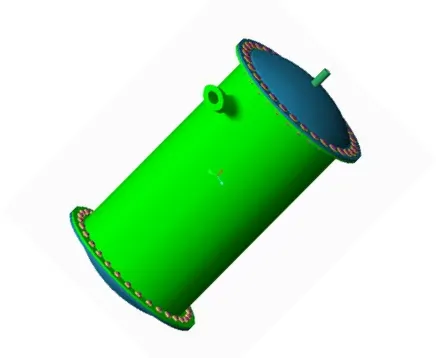
[image:2.612.196.414.480.659.2]The model is as shown in the figure 1 as shown below:
Fig. 1.Cryogenic Pressure VesselModel
ISSN 2250-3153
[image:3.612.74.513.50.323.2]www.ijsrp.org Fig. 2 Drawing Specifications for the Cryogenic Pressure Vessel.
IV. ANALYSISOFCRYOGENICPRESSUREVESSEL
The analysis of the Cryogenic Pressure Vessel is done in Ansys 15.0 and the analysis reports are as shown below.
[image:3.612.76.512.470.642.2]The geometry and the mesh model in Ansys are as shown in the Fig.3 and Fig. 4 below respectively.
Fig. 3 Geometry of the Cryogenic Vessel Fig.4 Mesh of the Cryogenic Vessel
The analysis is carried out for the Steel material and Different materials are being analysed for different conditions and materials used are Structural steel, Stainless steel, Aluminium and S- glass epoxy for the outer structure with aluminium, copper and stainless steel for the inner structure of the Cryogenic Pressure Vessel.
ISSN 2250-3153
www.ijsrp.org
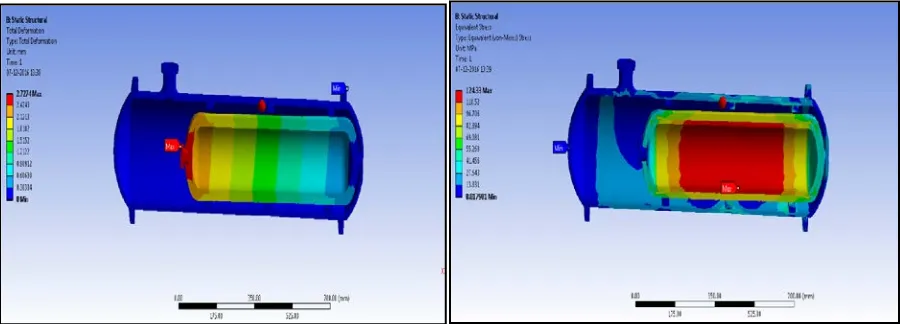
The Boundary Conditions are given Temperature of -173 degree C. Convection along with Inner pressure of 0.7 MPa also with Vacuum pressure along the inner and outer tubes. The deformation and Equivalent Stress reports for the steel Cryogenic Pressure Vesselwith Aluminium inner section are are as shown in the Fig. 5 and Fig. 6 respectively.
Fig. 5 Deformation of the Steel Cryogenic Vessel
Fig.6 Equivalent Stress of the Steel Cryogenic Vessel [image:4.612.74.505.102.252.2]
The deformation and Equivalent Stress reports for the composite Cryogenic Pressure Vessels with Copper inner section are are as shown in the Fig. 7 and Fig. 8 respectively.
Fig. 7 Deformation of the Steel Cryogenic Vessel
Fig.8 Equivalent Stress of the Steel Cryogenic Vessel [image:4.612.72.538.312.468.2]
Also the analysis is carried out for the cryogenic pressure vessel which consists of iterations of stainless steel and also glass epoxy composite material. The deformation and the Equivalent Stress reports for the glass epoxywith Aluminium inner position Cryogenic Pressure Vesselare as shown in the Fig. 9 and Fig. 10 respectively.
[image:4.612.73.523.546.708.2]ISSN 2250-3153
www.ijsrp.org
[image:5.612.74.526.121.296.2]The deformation and the Equivalent Stress reports for the glass epoxywith Copper inner position Cryogenic Pressure Vessel are as shown in the Fig.11 and Fig. 12 respectively.
Fig. 11 Deformation of the hybridCryogenic Vessel Fig.12 Equivalent Stress of the hybridCryogenic Vessel
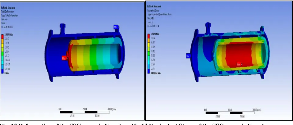
[image:5.612.73.553.374.579.2]The deformation and the Equivalent Stress reports for the stainless steelwith stainless steel inner position Cryogenic Pressure Vessel are as shown in the Fig.13 and Fig. 14 respectively.
Fig. 13 Deformation of the SSCryogenic Vessel Fig.14 Equivalent Stress of the SSCryogenic Vessel
Here analysis of cryogenic vessel done for outer vessel and inner vessel material changes, such as stainless steel, Glass epoxy, Aluminium and Structural steel for outer vessel.For inner vessel material used as copper, aluminium, stainless steel.
Analysis is done for following aspects.
• Temperature
• Heat Flux
• Equivalent Stress
• Equivalent Strain
ISSN 2250-3153
www.ijsrp.org
• Weight.
V. RESULTS AND DISCUSSION
The results for the cryogenic pressure for different variations are as shown below:
VI. CONCLUSION
This project work involves the comparison of material optimization of cryogenic pressure vessel under static loading conditions.The model is preferred of in Creo Parametric 2.0 and then analysis is performing through ANSYS 15.0. The Cryogenic pressure vessel is modeled in Creo Parametric 2.0 and analysis is carried out in Ansys 15.0. The analysis carried out is under static loading condition and also thermal base conditions. Different materials are being analyzed for different conditions and materials used are Structural steel, Stainless steel, Aluminum and S- glass epoxy for the outer structure with aluminum, copper and stainless steel for the inner structure. Taking weight into consideration and stress into account, S- glass epoxy for the outer structure with aluminum for the inner structure is comparably better than the other materials.
REFERENCES
[1] E. Lisowski, M. Domagała, “Simulation of liquid dynamics in a cryogenic mobile vessels”, Insitute of Applied Informatics, Cracow University of Technology, al. Jana Pawła 37, 31-864.
[2] K. J. Jaya Kumar, “Heat Transfer Analysis of Light Weight Cryogenic Tank for Space Vehicles”, Indian Journal of Science and Technology, Vol 8(4), 314-319, February 2015.
[3] SM. Aceves, J. Martinez-Frias, Garcia-Villazana, “Evaluation of Insulated Pressure Vessels for Cryogenic Hydrogen Storage”, American Society of Mechanical Engineers International Mechanical Engineering Congress and Exposition Nashville, TN November 14-19, 1999.
[4] Craig A. Stephens and Gregory J. Hanna, “Thermal Modeling and Analysis of a Cryogenic Tank Design Exposed to Extreme Heating Profiles”, NASA Contractor Report 186012.
[5] S. M. Aceves, J. Martinez-Frias, “Low Temperature and High Pressure Evaluation of Insulated Pressure Vessels for Cryogenic Hydrogen Storage”, O. Garcia-Villazana
FIMEE, Universidad de Guanajuato Salamanca, Gto. Mexico, Jan 2000.
Outer
Vessel
Inner
Vessel
Stress
(Mpa)
Strain
Deformation
(mm)
Heat Flux
Weight
Structural
steel
Aluminum
124.37
0.014
2.750
0.126
188.84
Structural
steel
Copper
112.39
0.012
2.389
0.012
234.40
Aluminum Aluminum
124.40
0.014
2.737
0.133
101.34
Aluminum
Copper
112.42
0.012
2.377
0.134
146.00
Aluminum
Stainless
steel
125.30
0.012
2.422
0.130
142.12
Stainless
steel
Aluminum
124.33
0.014
2.727
0.098
187.11
Stainless
steel
Copper
112.38
0.012
2.365
0.098
232.74
Stainless
steel
Stainless
steel
123.79
0.012
2.412
0.096
228.20
Glass
Epoxy
Aluminum
124.34
0.014
2.727
0.049
110.00
Glass
Epoxy
Copper
112.38
0.0121
2.440
0.052
143.72
Glass
Epoxy
Stainless
Steel
ISSN 2250-3153
www.ijsrp.org
[6] A. Hima Bindu, “Design and thermal analysis of cryogenic Fluid storage vessel”, International Journal for Research in Applied Science & Engineering Technology (IJRASET), Special Issue-3, November 2014
[7] Patel Pratik Kumar Baldev Bhai, Prof. Ronak Shah, “Design and Optimization of Cryogenic Storage Vessel”, IJEDR | Volume 3, Issue 1, 2014. [8] https://en.wikipedia.org.
AUTHORS
First Author – B. Arun Kumar,M. Tech, Machine Design, Department of Mechanical Engg, Raghu Institute of Technology, Visakhapatnam
Second Author – DrV.NagaBhushana Rao, Professor, Department of Mechanical Engg, Raghu Institute of Technology, Visakhapatnam.