Pure Bending Analysis of Isotropic Thin Rectangular
Plates Using Third-Order Energy Functional
Emmanuel C. Oba
1, Pius C. Anyadiegwu
2, Abednego G. T. George
3, and Ethelbert C. Nwadike
4* Civil Engineering Department, Federal University of Technology Owerri, Nigeria. *
Civil Engineering Department, Federal Polytechnic Owerri, Nigeria.
DOI: 10.29322/IJSRP.8.3.2018.p7537 http://dx.doi.org/10.29322/IJSRP.8.3.2018.p7537
Abstract- Studies previously carried out on pure bending analysis of isotropic thin rectangular plate using total potential energy functional have mainly used second order (Ritz energy function) and fourth order (Galerkin and work error energy functional). The objective of this study is pure bending analysis of isotropic thin rectangular CCCC, CSCS, CSSS and SCCC plates. In this paper, third order energy functional is used for analysis. The Rayleigh Ritz energy method of direct variation approach for plate analysis is adopted. The third order energy functional method is derived from first principle by using equations and principles of theory of elasticity. Polynomial series is used to formulate the approximate shape functions for the plate with various boundary conditions. Direct variational calculus was applied on the third-order energy function to obtain the coefficient of deflection which was used to determine the stiffness component for the plates. The coefficients of deflection for CCCC, CSCS, CSSS and SCCC are obtained for various aspect ratios (ranging from 1.0 to 2.0 at the increment of 0.1). The various coefficient of deflection is used to obtain the deflection at the center of the plates. The central deflection of the various plate with aspect ratio (ranging from 1.0 to 2.0 at the increment of 0.1) from this studies were compared with the values of Szilard (2004) and Timoshenko and Krieger (1959). From the comparison, it was observed that the maximum percentage difference recorded for CCCC, CSCS and CSSS plates was 3.58, 4.91 and 1.79 respectively. While for SCCC there was no significant difference. These values of percentage differences are relatively small, which indicates that the method of this present study is considered adequate, satisfactory and reliable for analyzing pure bending isotropic thin rectangular plate.
Index Terms- Pure bending analysis, third order energy functional, thin plate, boundary conditions, theory of elasticity.
Paper Type- Research paper
Nomenclature:
x The primary axis of the plate. That is the shorter of the two axes of the major plane of the plate. y The secondary axis of the plate. That is the longer of the two axes of the major plane of the plate.
z The tertiary axis of the plate. That is the shortest of the three axes of the plate.
a Length of the primary dimension of the plate.
b Length of the secondary dimension of the plate. t Thickness of the plate or the length of the tertiary dimension of the plate.
It is the aspect ratio. That is = b/a S Simple support
C Clamped or fixed support.
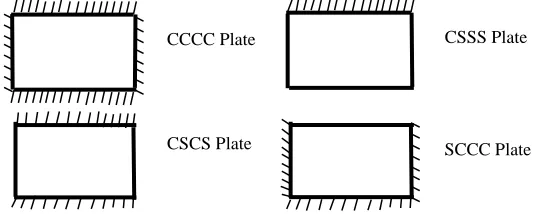
CCCC Four edges of the plate are clamped. CSCS Two opposite edges of the plate are simple
supported and the other opposite edges are clamped. CSSS Two opposite edges of the plate are both simple support and the other two edges of the plate are clamped and simple supported
SCCC Two opposite edges of the plate are both clamped and the other two edges of the plate are simple supported and clamped
u Displacement of the plate in x direction. v Displacement of the plate in y direction. w Transvers deflection
σ Normal stress Normal strain E Modulus of elasticity V External work
U Internal (strain) energy Shear stress of the plate Shear strain of the plate
µ Poisson’s ratio
D Modulus of flexural rigidity of the plate A Coefficient of deflection
h Shape (profile) function
Π Total potential energy of the plate
R Non dimension axis (quantity) parallel to x axis R = x/a
Q Non dimension axis (quantity) parallel to y axis Q = x/a
dR dR = dx/a dQ dQ = dy/b
I. INTRODUCTION
hydraulic structures, pavements, containers, airplanes, missiles, ships, instruments and machines parts.
Pure bending is a condition of stress where a bending moment is applied to a plate without the simultaneous presence of axial, stress, or torsional force. Rectangular plate has four edges and the edges are numbered as shown in Fig 1.0. Also the three rectangular plates considered in this research are shown in Figure 1.1.
[image:2.612.34.301.293.400.2]
[image:2.612.317.574.322.474.2]
Figure 1.0. Sketch of rectangular plate with edge numbering
Figure 1.1. Plates of various boundary conditions.
The difficult in obtaining exact solution to the classical plate governing differential equation by integration gave prelude to the use of energy approach to plate analysis. Typical of energy method is the use of assumed shape (displacement) functions. The closer the assumed shape is to the exact shape function, the more accurate the result. If the assumed shape function is far from the exact shape function, the resulting answer will differ from the exact answer by wide margin. Thus, earlier scholars made several efforts in coming up with different assumed shape functions that seem close to the exact shape function. This is usually confirmed by comparing the result emanating from the work with assumed shape function with the result obtain from numerical methods like finite element method. Some of the energy methods in use are Ritz energy method and Galerkin energy method (Ibearugblem, et al., 2013, Ezeh et al., 2014, Ozuluonye et al., 2014). Later, some scholars used work-error energy method (Eziefula et al., 2014, Onwuka et al., 2015, Ibearugblem, et al., 2015). Use of trigonometric function in the assumed shape functions dominated research in classical plate analysis prior to the year 2012 when Ibearugblem evolved polynomial shape function (Ibearugblem et al., 2012). Later, Ibearugblem et al. 2014 confirmed that the assumed polynomial shape function is exact shape function by direst integration of the governing differential equation of the classical plate. In this present work, the polynomial shape function will be adopted.
The Ritz energy method is a direct varietional method to finding an approximate solution for continuum problems. The Ritz energy method has a function with "second derivative" as the highest order of derivative. The Galerkin energy method is a broad generalization of the Ritz method and is used primarily for the approximation solution of variational and boundary values problems, including problems that do not reduced to variational problems. In Galerkin energy method, the highest order of derivative is four. This is the same with work-error method. The difference between work-error method and Galerkin method is that while the later cannot be subject to variation, the work-error method is subject to variation. The Ritz energy functional is shown on equation 1.
Π=𝐷
2∫ ∫ [( 𝜕2𝑤
𝜕𝑥2) 2
+ 2 (𝜕
2𝑤
𝜕𝑥𝜕𝑦)
2
+ (𝜕
2𝑤
𝜕𝑦2) 2
] 𝜕𝑥𝜕𝑦
𝑏
0 𝑎
0
−q ∫ ∫ 𝑤
𝑏
0
𝜕𝑥𝜕𝑦
a
0
(1)
Energy functional for Galerkin and work-error are shown on equations (2) and (3) respectively.
Π= ∫ ∫ (𝜕
4𝑤
𝜕𝑥4. 𝑤 + 2
𝜕4𝑤 𝜕𝑥2𝜕𝑦2. 𝑤 +
𝜕4𝑤 𝜕𝑦4. 𝑤) 𝑏
0 𝑎
0
𝜕𝑥𝜕𝑦
−𝑞
𝐷∫ ∫ 𝑤
𝑏
0
𝜕𝑥𝜕𝑦
a
0
= 0 (2)
Π=1
2∫ ∫ ( 𝜕4𝑤
𝜕𝑥4. 𝑤 + 2
𝜕4𝑤
𝜕𝑥2𝜕𝑦2. 𝑤 +
𝜕4𝑤
𝜕𝑦4. 𝑤) b
0 a
0
∂x ∂y
−q
D∫ ∫ 𝑤
𝑏
0
𝜕𝑥𝜕𝑦
a
0
(3)
It is noteworthy that no previous research has used an energy functional with third derivative as the highest order of derivative in pure bending analysis of isotropic thin rectangular plates. In view of this, the research focused on using third order energy functional in pure bending analysis of isotropic CCCC, CSCS, CSSS and SCCC plates. This method aims to bridge the gap created by second and fourth order energy functional used for pure bending analysis of isotropic thin rectangular plates.
II. ANALYTICAL METHOD
FORMULATIN OF THIRD-ORDER ENERGY FUNCTION
For a homogeneous rectangular thin isotropic plate, it is assumed that the thickness of the plate in the z-axis is relatively small compared with the other characteristic dimension in the x-axis and y-axis respectively. The theory of elasticity was used to formulate the third-order energy functional. The sequence of the formulation includes: kinematic, strains-deflection relationships, stress-strain (constitutive) relationship, stress-deflection relationship and total potential energy.
KINEMATICS
Edge 3 Edge 1
E
d
g
e
2 E
d
g
e
4
CSCS Plate CCCC Plate
The displacement of a thin rectangular plate includes in-plane displacements u and v and out of plane displacement (deflection) w. The vertical normal strain of a plate is equal to zero. Consequently, upon this the vertical shear strains are negligible in classical plate analysis and assumed to be equal to zero. The six engineering strain components of a plate are defined in terms of displacements as:
Ɛx =
∂u
∂x (4) Ɛy=
∂v
∂y (5)
γxy=
𝜕𝑢 𝜕𝑦 +
∂v
𝜕𝑥 (6)
Ɛz=
𝜕𝑤
𝑑𝑧 = 0 (7) γxz=
𝜕𝑢 𝜕𝑧+
∂w
𝜕𝑥 = 0 (8) γyz =
∂v ∂z+
∂w
∂y = 0 (9)
STRAINS-DEFLECTION RELATIONSHIPS
The relationships that exit between the in-plane strain components (x, y, andxy) and the out of plane displacement, w. Solving out equation (8) gave:
u = −z ∂w
∂x (10)
Similarly, solving out equation (9) gave:
v = −z ∂w
∂y (11)
Substituting equations (10) and (11) into equations (4) and (5) respectively gave:
Ɛ𝑥 = −𝑧
𝜕2𝑤
𝜕𝑥2 (12)
Ɛ𝑦 = −𝑧
𝜕2𝑤
𝜕𝑦2 (13) Similarly, substituting equations (4) and (5) into equation (6) gave:
γxy= −2𝑧
𝜕2𝑤
𝜕𝑥𝜕𝑦 (14)
STRESS-STRAINS RELATIONSHIPS
From the classical plate assumptions, the effects of normal stress and vertical shear stresses (z: xz: yz) on the gross response of the plate are negligible when compared with the effects from the in-plane stresses (x ; y: xy). This leaves us with only three stress components: (x; y; xy). The resulting constitutive equations include:
𝜎𝑥=
𝐸
1– µ2(𝜀𝑥+ µ𝜀𝑦) (15)
𝜎𝑦=
𝐸
1– µ2(µ𝜀𝑥+ 𝜀𝑦) (16)
𝜏𝑥𝑦=
𝐸(1 – µ)
2(1 – µ2)γ𝑥𝑦 (17)
STRESS-DEFLECTION RELATIONSHIPS
This is done to obtain the relationships, which exist between the in-plane stresses and the out of plane displacement. Substituting equations (12) and (13) into equation (15) gave:
𝜎𝑥=
−𝐸𝑧 1– µ2(
𝜕2𝑤
𝜕𝑥2+ µ
𝜕2𝑤
𝜕𝑦2) (18) Similarly, substituting equations (12) and (13) into equation (16) gave:
𝜎𝑦=
−𝐸𝑧 1– µ2( µ
𝜕2𝑤
𝜕𝑥2+
𝜕2𝑤
𝜕𝑦2) (19) Furthermore, substituting equation (14) into equation (17) gave:
𝜏𝑥𝑦= −
𝐸𝑧(1 – µ) (1 – µ2)
𝜕2𝑤
𝜕𝑥𝜕𝑦 (20)
TOTAL POTENTIAL ENERGY
Strain energy is defined as average of indefinite summation of the product of stress and strain at every point in the plate within the plate domain. This is given mathematically as:
U =1
2∭ σε dxdydz
xyz
(21)
That is
U =1
2∬ [ ∫ σε dz
h/2
−h 2⁄
]
xy
dxdy (22)
Let U̅ = ∫ σε dz
h 2⁄
−h 2⁄
(23)
That means
U =1 2∬ U̅
xy
dxdy (24)
But σε = σxεx+ σy εy + τxy γxy (25)
The external work due to lateral load uniformly distributed on the plate, q is given as:
V = −q ∬ w dxdy
xy
(26)
Total potential energy is the summation of strain energy and external work given as:
Π = U + V (27)
σxεx=
𝐸𝑧2
1– µ2([
𝜕2𝑤
𝜕𝑥2] 2
+ µ [𝜕
2𝑤
𝜕𝑥𝜕𝑦]
2
) (28)
Similarly, multiplying equations (13) and (16) gave:
𝜎𝑦𝜀𝑦=
𝐸𝑧2
1– µ2([
𝜕2𝑤
𝜕𝑦2] 2
+ µ [𝜕
2𝑤
𝜕𝑥𝜕𝑦]
2
) (29)
And multiplying equations (14) and (17) gave:
𝜏𝑥𝑦γxy= 2
𝐸𝑧2(1 – µ)
(1 – µ2) [
𝜕2𝑤
𝜕𝑥𝜕𝑦]
2
(30)
Now, let us add equations (28), (29) and (30). Substituting this addition into equation (23) gave:
U̅ = 𝐷 ([𝜕
2𝑤
𝜕𝑥2] 2
+ 2 [𝜕
2𝑤
𝜕𝑥𝜕𝑦]
2
+ [𝜕
2𝑤
𝜕𝑦2] 2
) (31)
Substituting equation (31) into equation (24) gave the stain energy equation as:
U = 𝐷 2∬ ([
𝜕2𝑤
𝜕𝑥2] 2
+ 2 [𝜕
2𝑤
𝜕𝑥𝜕𝑦]
2
+ [𝜕
2𝑤
𝜕𝑦2] 2
)
xy
dxdy (32)
Mathematically, this equation can be rewritten as:
U =𝐷
2∫ ∫ ( ∂3𝑤
∂𝑥3.
∂𝑤 ∂x + 2
∂3𝑤
∂x ∂y2.
∂w ∂x b 0 a 0 +∂ 3𝑤
∂𝑦3.
∂𝑤
∂y) dxdy (33a)
or:
U =𝐷
2∫ ∫ ( ∂3𝑤
∂𝑥3.
∂𝑤 ∂x + 2
∂3𝑤
∂𝑥2∂y.
∂w ∂y b 0 a 0 +∂ 3𝑤
∂𝑦3.
∂𝑤
∂y) dxdy (33b)
Substituting equations (26) and (33) into equation (27) we obtain the third-order energy functional for plate in pure bending as:
∏ = −𝐷
2∫ ∫ ( ∂3𝑤
∂𝑥3.
∂𝑤 ∂x + 2
∂3𝑤
∂x ∂y2.
∂w ∂x+
∂3𝑤
∂𝑦3.
∂𝑤 ∂y) b 0 a 0 dxdy
− q ∫ ∫ w
b
0 a
0
dxdy (34a)
or:
∏ = −𝐷
2∫ ∫ ( ∂3𝑤
∂𝑥3.
∂𝑤 ∂x + 2
∂3𝑤
∂𝑥2∂y.
∂w ∂y+
∂3𝑤
∂𝑦3.
∂𝑤 ∂y) b 0 a 0 dxdy
− q ∫ ∫ w
b
0 a
0
dxdy (34b)
Let deflection (out of plane displacement) be defined as:
w = Ah (35)
Substituting equation (35) into equation (34) gave:
∏ = −𝐴
2𝐷
2 ∫ ∫ ( ∂3ℎ
∂𝑥3.
∂ℎ ∂x+ 2
∂3ℎ
∂x ∂y2.
∂h ∂x+
∂3ℎ
∂𝑦3.
∂ℎ ∂y) b 0 a 0 dxdy
−qA ∫ ∫ h
b
0 a
0
dxdy (36a)
or:
∏ = −𝐴
2𝐷
2 ∫ ∫ ( ∂3ℎ
∂𝑥3.
∂ℎ ∂x+ 2
∂3ℎ
∂x2∂y.
∂h ∂y+
∂3ℎ
∂𝑦3.
∂ℎ ∂y) b 0 a 0 dxdy
−qA ∫ ∫ h
b
0 a
0
dxdy (36a)
DIRECT VARIATION OF TOTAL POTENTIAL ENERGY
Differentiating equation (36) with respect to deflection coefficient, A gave:
dΠ
dA= −AD ∫ ∫ ( ∂3ℎ
∂𝑥3.
∂ℎ ∂x+ 2
∂3ℎ
∂x ∂y2.
∂h ∂x+
∂3ℎ
∂𝑦3.
∂ℎ ∂y) b 0 a 0 dxdy
−q ∫ ∫ h
b
0 a
0
dxdy = 0 (37a)
or:
dΠ
dA= −AD ∫ ∫ ( ∂3ℎ
∂𝑥3.
∂ℎ ∂x+ 2
∂3ℎ
∂x2∂y.
∂h ∂y+
∂3ℎ
∂𝑦3.
∂ℎ ∂y) b 0 a 0 dxdy
−q ∫ ∫ h
b
0 a
0
dxdy = 0 (37b)
Rearranging equation (37) by making A the subject of the equation gave:
A = −q ∫ ∫ h
b 0 a
0 dxdy
D ∫ ∫ (∂∂𝑥3ℎ3.
∂ℎ
∂x+ 2
∂3ℎ
∂x ∂y2.
∂h
∂x+
∂3ℎ
∂𝑦3.
∂ℎ ∂y) b 0 a 0 dxdy (38a) or:
A = −q ∫ ∫ h
b 0 a
0 dxdy
D ∫ ∫ (∂∂𝑥3ℎ3.
∂ℎ
∂x+ 2
∂3ℎ
∂x2∂y.
∂h
∂y+
∂3ℎ
∂𝑦3.
∂ℎ ∂y) b 0 a 0 dxdy (38b)
Now let us define the principal in-plane coordinates (x and y) in terms of non-dimension in-plane coordinates (R and Q) as:
x = aR (39) y = bQ (40)
α =b
Substituting equations (39), (40) and (41) into equation (38) gave:
A = −qa
4∫ ∫ h1 0 1
0 dRdQ
D ∫ ∫ (∂∂𝑅3ℎ3.
∂ℎ
∂R+
2
𝛼2
∂3ℎ
∂R ∂Q2.
∂h
∂R+
1
𝛼4
∂3ℎ
∂𝑄3.
∂ℎ ∂Q) 1 0 1 0 dRdQ (42a) or:
A = −qa
4∫ ∫ h1 0 1
0 dRdQ
D ∫ ∫ (∂𝑅∂3ℎ3.
∂ℎ
∂R+
2
𝛼2
∂3ℎ
∂R2∂Q.
∂h
∂Q+
1
𝛼4
∂3ℎ
∂𝑄3.
∂ℎ ∂Q) 1 0 1 0 dRdQ (42b)
Equation (42) can be written in designated form as:
A =qa
4
D (
−k4
k1+ 2
𝛼2k2+
1
𝛼4k3
) (43)
Where k1, k2, k3 and k4 are defined as follows:
k1= ∫ ∫
∂3ℎ
∂𝑅3.
∂ℎ ∂RdRdQ 1 0 1 0 (44)
k2= ∫ ∫
∂3ℎ
∂R ∂Q2.
∂h ∂RdRdQ 1 0 1 0 (45a) or:
k2= ∫ ∫
∂3ℎ
∂R2∂Q.
∂h
∂QdRdQ (45a)
1
0 1
0
k3= ∫ ∫
∂3ℎ
∂𝑄3.
∂ℎ ∂QdRdQ 1 0 1 0 (46)
k4= ∫ ∫ h 1
0 1
0
dRdQ (47)
Where the k parameters are the stiffness components of the rectangular plate.
NUMERICAL EXAMPLE
Analyze a classical isotropic thin rectangular plate using third-order-energy functional with:
i. CCCC Plate with w = A(R2 -2R3 + R4)(Q2 -2Q3 + Q4) ii. CSCS Plate with w = A(R -2R3 + R4)(Q2 -2Q3 + Q4) iii. CSSS Plate with w = A(R -2R3 + R4)(1.5Q2– 2.5Q3 + Q4) iv. SCCC Plate with w = A(R2 -2R3 + R4)(1.5Q2– 2.5Q3 + Q4)
CCCC Plate:
k1= ∫ ∫
∂3ℎ
∂𝑅3.
∂ℎ ∂RdRdQ 1 0 1 0
= −2
1575 (48)
k2= ∫ ∫
∂3ℎ
∂R ∂Q2.
∂h ∂RdRdQ 1 0 1 0
= −4
11025 (49)
k3= ∫ ∫
∂3ℎ
∂𝑄3.
∂ℎ ∂QdRdQ 1 0 1 0
= −2
1575 (50)
k4= ∫ ∫ h 1
0 1
0
dRdQ = 1
900 (51)
Substituting equations (48), (49), (50) and (51) into equation (43) gave:
A =qa
4
D (
1 900
[ 2
1575] +
2
∝2[
4
11025] +
1
∝4[
2
1575]
) (52)
CSCS Plate:
k1= ∫ ∫
∂3ℎ
∂𝑅3.
∂ℎ ∂RdRdQ 1 0 1 0
= −4
525 (53)
k2= ∫ ∫
∂3ℎ
∂R ∂Q2.
∂h ∂RdRdQ 1 0 1 0
= −34
3675 (54)
k3= ∫ ∫
∂3ℎ
∂𝑄3.
∂ℎ ∂QdRdQ 1 0 1 0
= −62
1575 (55)
k4= ∫ ∫ h 1
0 1
0
dRdQ = 1
150 (56)
Substituting equations (53), (54), (55) and (56) into equation (43) gave:
A =qa
4
D (
1 150
[ 4
525] +
2
∝2[
34
3675] +
1
∝4[
62
1575]
) (57)
CSSS Plate:
k1= ∫ ∫
∂3ℎ ∂𝑅3.
∂ℎ ∂RdRdQ 1 0 1 0
= −19
525 (58)
k2= ∫ ∫
∂3ℎ
∂R ∂Q2.
∂h ∂RdRdQ 1 0 1 0
= −51
1225 (59)
k3= ∫ ∫
∂3ℎ
∂𝑄3.
∂ℎ ∂QdRdQ 1 0 1 0
= −31
350 (60)
k4= ∫ ∫ h 1
0 1
0
dRdQ = 3
200 (6l)
A =qa
4
D (
3 200
[19
525] +
2
∝2[
51
1225] +
1
∝4[
31
350]
) (62)
SCCC Plate:
k1= ∫ ∫
∂3ℎ
∂𝑅3.
∂ℎ ∂RdRdQ
1
0 1
0
= −1
350 (63)
k2= ∫ ∫
∂3ℎ
∂R ∂Q2.
∂h ∂RdRdQ
1
0 1
0
= −2
1225 (64)
k3= ∫ ∫
∂3ℎ
∂𝑄3.
∂ℎ ∂QdRdQ
1
0 1
0
= −19
3150 (65)
k4= ∫ ∫ h 1
0 1
0
dRdQ = 3
1200 (66)
Substituting equations (58), (59), (60) and (61) into equation (43) gave:
A =qa
4
D (
3 1200
[ 1
350] +
2
∝2[
2
1225] +
1
∝4[
19
3150]
) (67)
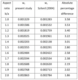
III. RESULT AND DISCUSSION
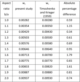
The values of the center deflection for CCCC and CSCS plates analyzed for different aspect ratio are presented on tables 3.1 and 3.2. These values of the center deflection for the various plates obtained in this work were compared with the values obtained by Szilard (2004) on table 3.1, Timoshenko and Krieger (1959) on tables 3.2 respectively. Their relationships with present studies is shown graphically on figure A.1, A.2, A.3 and A.4 respectively. From table 3.1, it is obvious that the values from this present work are upper bound to the values in the works of Szilard (2004) and very close to it. The maximum percentage difference encountered is 3.58%. By statistical standards, this difference is regarded not being significant. The reason for this difference may not be as a result of the energy functional used but as a result of different deflection functions used. While the present work used Ibearugbulem's polynomial deflection equation, Szilard used trigonometric deflection equation. From tables 3.2 and 3.3, the values of the central deflection for CSCS and CSSS plates obtained in this work were compared with the values obtained by Timoshenko and Krieger (1959). It is obvious that the values from the present work are upper bound to the values in the works of Timoshenko and Krieger (1959) and very close to it. The maximum percentage difference encountered is 4.91% for CSCS plate and 1.79% for CSSS plate. This means that at 95% and 98% confidence level, one can say that the values from this study is the same with the values from the works of Timoshenko and Krieger (1959). By statistical standards, this maximum difference of 4.91% and 1.79% are regarded not being significant. The reason for this difference may not be as a result of the energy functional used but as a result of different deflection functions used. While the present work used Ibearugbulem's polynomial deflection equation, Timoshenko and Krieger used trigonometric
deflection equation. The values of the central deflection for SCCC plate obtained in this work were compared with the values obtained by Ozuluonye (2014) on table 3.4.
From Table 3.4, it can be seen that the values from the present work is exactly equal to the values in the works of Ozuluonye (2014). The reason for this exactness is majorly because both the present study and the works of Ozuluonye (2014) used the same energy functional (Ibearugbulem polynomial deflection equation). This also goes a long way to justify the third-order energy functional as a veritable energy functional for rectangular plate analysis
Table 3.1: Center Deflection of CCCC plate. Aspect
ratio
b/a
wc
present study
wc
Szilard (2004)
Absolute
percentage
difference
1.0 0.001329 0.001283 3.58
1.1 0.001586 0.001532 3.53
1.2 0.001819 0.001759 3.40
1.3 0.002025 0.001961 3.22
1.4 0.002203 0.002138 3.01
1.5 0.002355 0.002291 2.80
1.6 0.002484 0.002422 2.58
1.7 0.002594 0.002534 2.38
1.8 0.002688 0.002630 2.19
1.9 0.002768 0.002713 2.02
[image:6.612.304.565.312.581.2]2.0 0.002863 0.002784 1.86
Table 3.2: Center Deflection of CSCS plate. Aspect
ratio
b/a
wc
present study
wc
Timoshenko and Krieger
(1959)
Absolute
percentage
difference
1.0 0.00199 0.00192 3.56
1.1 0.00261 0.00251 4.17
1.3 0.00402 0.00388 3.73
1.4 0.00477 0.00460 3.66
1.5 0.00551 0.00531 3.82
1.6 0.00624 0.00603 3.55
1.7 0.00695 0.00668 4.04
1.8 0.00762 0.00732 4.15
1.9 0.00826 0.00790 4.55
[image:7.612.29.286.335.601.2]2.0 0.00885 0.00 844 4.91
Table 3.3: Center Deflection of CSSS plate. Aspect
ratio
b/a
wc
present study
wc
Timoshenko and Krieger
(1959)
Absolute
percentage
difference
1.0 0.00282 0.00280 0.59
1.1 0.00354 0.00350 1.15
1.2 0.00429 0.00430 0.34
1.3 0.00503 0.00500 0.61
1.4 0.00576 0.00580 0.69
1.5 0.00646 0.00640 0.95
1.6 0.00713 0.00700 1.79
1.7 0.00775 0.00770 0.65
1.8 0.00833 0.00820 1.61
1.9 0.00887 0.00880 0.81
2.0 0.00937 0.00930 0.74
Table 3.4: Center Deflection of SCCC plate. Aspect
ratio
b/a
wc
present study
wc
Ozuluonye
(2014)
Absolute
percentage
difference
1.0 0.00161 0.00161 0
1.1 0.00183 0.00183 0
1.2 0.00202 0.00202 0
1.3 0.00218 0.00218 0
1.4 0.00231 0.00213 0
1.5 0.00243 0.00243 0
1.6 0.00252 0.00252 0
1.7 0.00260 0.00260 0
1.8 0.00267 0.00267 0
1.9 0.00273 0.00273 0
2.0 0.00278 0.00278 0
IV. CONCLUSION
Based on the result obtained, the following conclusions were drawn:
1. The third-order energy functional used in this study is mathematically the same with the energy functional of Galerkin and Ritz. The functional with highest order of derivative of three proved to produce the same response with the Galerkin's functional (fourth-order functional) and Ritz functional (second-order functional).
2. The values of deflections at the centers of the plate obtained herein are very close to the results obtained by previous research works that used different methods of analysis.
APPENDIX A
Figure A.1: Center deflection wc against the aspect ratio for CCCC plate
[image:8.612.42.295.67.269.2] [image:8.612.318.572.284.477.2]. Figure A.2: Center deflection wc against the aspect ratio for CSCS plate
Figure A.3: Center deflection wc against the aspect ratio for CSSS plate
Figure A.4: Center deflection wc against the aspect ratio for SSSC plate
ACKNOWLEDGMENT
The authors are grateful to the faculty of Civil Engineering, Federal University of Technology Owerri for their support towards the successful completion of this research work. The staff and management of FUTO and Federal Polytechnic Nekede Owerri libraries for their assistance in availing literature and internet materials for this research work.
REFERENCES
[1]Boobnoff I.G. (1902). On the stresses in a ship's bottom plating due to water pressure. Trans. Instn nav. Archit. 44 pp.15–52.
[2] Damanpack, A. R. BodaghiI, M.; Ghassemi, H. and Sayehbani, M. (2013). Boundary element method applied to the bending analysis of thin functionally graded plates. Lat. Am. J. solids struct. vol.10 no.3 Rio de Janeiro
[3] Szilard, R. (2004). Theories and Applications of plate analysis (Classical, Numerical and Engineering Methods). New Jersey: John Wiley & Sons.
Ugural, A. C. (1999). Stresses in plates and shells (2nd Ed.). Singapore: McGraw-hill.
0 0.0005 0.001 0.0015 0.002 0.0025 0.003
1 1.1 1.2 1.3 1.4 1.5 1.6 1.7 1.8 1.9 2
C
ent
re
D
ef
le
ct
io
n,
W
c
Aspect Ratio, b/a
CCCC Plate
Wc Present Study
Wc Szilard (2004)
0 0.001 0.002 0.003 0.004 0.005 0.006 0.007 0.008 0.009 0.01
1 1.1 1.2 1.3 1.4 1.5 1.6 1.7 1.8 1.9 2
Aspect Ratio, b/a
CSCS Plate
Wc Present Study
Wc Timoshenko & Krieger(1959)
0 0.001 0.002 0.003 0.004 0.005 0.006 0.007 0.008 0.009 0.01
1 1.1 1.2 1.3 1.4 1.5 1.6 1.7 1.8 1.9 2
C
ent
re
D
ef
le
ct
io
n
Aspect Ratio, b/a
CSSS Plate
Wc Present Study
Wc Tjmoshenko & Krieger(1959)
0 0.0005 0.001 0.0015 0.002 0.0025 0.003
1 1.1 1.2 1.3 1.4 1.5 1.6 1.7 1.8 1.9 2
C
ent
re
D
ef
le
ct
io
n,
Kc
Aspect Ratio, b/a
SCCC Plate
Wc Present Study
[image:8.612.36.298.301.499.2][4]Ibearugbulem, O. M., Ibeabuchi, V. I., and Njoku, K. O. (2014). Buckling analysis of ssss stiffened rectangular isotropic plates using work principle approach. Intl. Journal of Innovative Research and Development, vol. 3, issue 11, pp. 169 – 176.
[5]Inglis, C. E. ((1925)., Stresses in rectangular plates clamped at their edges and loaded with a uniformly distributed pressure. Trans. Instn nav. Archit. 67(1925) 147–165. L.
[6]Ibearugbulem, O. M., Onwuka, D. O., and Eziefu la, U. G. (2013). Inelastic buckling analysis of axially compressed thin cccc plates using Taylor-Maclauriun displacement function. Academic Research International, vol 4, No. 6, pp. 594 – 600.
[7]Ibearugbulem, O. M. & Ezeh, J. C. (2013), Instablity of axially compressed cccc thin rectangular plate using taylor-mclaurin’s series shape function on Ritz method, Academic Research International, Vol. 4. No. 1 January 2012, Pp. 346 -351ISSN-L: 2223-9553, ISSN: 2223-9944
[8] Koialovich, B. M. (1902)., On one partial differential equation of the fourth order (Doctor dissertation). St. Petersburg University Press, St. Petersburg (1902), (in Russian). (German abstract in Jb Fortschr. Math. 33 367–368.) [9]Rahbar-Ranji, Ahmad and Bahmyaria, E. (2012). Bending Analysis of Thin Plates with Variable Thickness Resting on Elastic Foundation by Element Free Galerkin Method. Journal of Mechanics / Volume 28 / Issue 03 / September 2012, pp 479-488
[10]J. C. Ezeh, Ibearugbulem, M. Owus, H. E. Opara, and, O. A. Oguaghamba (2014), Galerkin’s Indirect Variational Method in Elastic Stability Analysis of All Edges Clamped Thin Rectangular Flat Plates, International Journal of Research in Engineering and Technology eISSN: 2319-116 pISSN: 2321-7308, Volume: 03 Issue: 04, pp. 674 – 679, www.ijret.org
[11]J. C. Ezeh, O. M. Ibearugbulem, K. O. Njoku & L. O. Ettu (2013), Dynamic Analysis of Isotropic SSSS Plate Using Taylor Series Shape Function in Galerkin’s Functional, International Journal of Emerging Technology and
Advanced Engineering, ISSN 2250-2459, ISO 9001:2008 Certified Journal, Vol. 3, Issue 5, May 2013, pp. 372-375
[12]K. O. Njoku, J. C. Ezeh, O. M. Ibearugbulem, L. O. Ettu & L. Anyaogu (2013), Free Vibration Analysis of Thin Rectangular Isotropic CCCC Plate Using Taylor Series Formulated Shape Function in Galerkin’s Method, Academic Research International Part-I:Natural and Applied Science, ISSN-L:2223-9553, ISSN:2223-9944, Vol. 4 No. 4 July 2013, pp. 126-132
[13] Wang,Y. Y. Lam, K. Y. and Liu, G. R. (2010). Bending Analysis of Classical Symmetric Laminated Composite Plates by the Strip Element Method. Mechanics of Composite Materials and Structures, Volume 7, Issue 3 pages 225-247
AUTHORS
First Author - Emmanuel Chinedu Oba, B.Eng.,
Federal University of Technology Owerri, Nigeria. [email protected]
Second Author – Pius Chibueze Anyadiegwu, M.Eng., Federal Polytechnic Nekede Owerri, Nigeria.
Third Author - Abednego. G. T. George, M.Eng.,
Federal University of Technology Owerri, Nigeria. [email protected]
Forth Author – Ethelbert Chukwunonye Nwadike, M.Eng., Federal Polytechnic Nekede Owerri, Nigeria.