www.ijsrp.org
A Study and Overview on Hybrid Technologyfor Next
Generation Advanced Communication System
Sudip Bandyopadhyay
1, Anirban Ghosal
2, Jayanta Kr. Ray
3, Swati Banerjee
4& Dr.Biswarup Neogi
51Lecturer, CST Dept. Technique Polytechnic Institute, Hooghly, W.B., INDIA
3Faculty,ECEDept.,Kanad Institute of Engineering Management, Mankar,Burdwan,W.B,INDIA
4Assistant Professor, Narula Institute Of Technology, Agarpara, WB,INDIA
2,5Faculty,ECE Dept.,JIS College of Engineering, Nadia,W.B,INDIA.
Abstract: The use of multiple antennas at both transmitter and receiver to formmultiple input and multiple output (MIMO) channels currently hold the potential to drastically improve wireless links spectrum efficiency or robustness, increasing capacity and the ability to increase the transmission speed in future wireless communications system as well as radar. For broadband communications, OFDM turns a frequency selective channel into a set of parallel flat channels, which significantly reduces the receiver complexity.Problems in multipath fading and interference are severe on road condition and environment also so dynamic. Existing wireless system may be utilized single frequency, singleantenna and pulse for multicarrier transmissionand reception. Problems of such system are that in case offailure the total system will become non-operational A distributed system in terms of multicarrier, multiantenna and coded pulse can provide a more suitable communication and sensor give rise toHybrid (SS-OFDM-MIMO) technology is the ultimate solution. The hybrid approach has been essentially been developed for 60GHz frequency provided we have the necessary bandwidth.The performance analysis for the MIMO-OFDM system has been carried out based on MATLAB simulation. The experimental results have been verified using the simulation, the results of simulation have been verified with the various works being carried out in this area and the results conferred to be correct.
Index Terms:Hybrid, SS, MIMO OFDM, MRC,
STBC,V-BLAST
I. INTRODUCTION
ll wireless technologies face the challenges of signal fading, multipath, increasing interference and limited spectrum.MIMO technology has recently been demonstrated to have the potential of achieving extraordinary data rates and simultaneous increase in range and reliability without consuming extra radio frequency. It solves speed and range of
the toughest problems facing any wireless communication today. Commercial products are available supporting 2Mbps and 300 Mbps data rates over Mobile and WLAN based wireless communication system respectively and the developments tend towards providing 100 Mbps and 1Gbps data rate for the two cases. In a comparison between the Wi-Fi G adapters with Wi-Fi N, it is found that G adapters with only one antenna supports a maximum data rate of 54 Mbps utilizing OFDM technology at its physical layer ,where as N adapters with multiple antennas utilizing MIMO technology. The data rate of today existing SISO system is determined by the formula: R=Es * BW, where R is the data rate (bits /second).Es is the spectral efficiency (bits /sec/Hz) and BW is the communication bandwidth (Hz). An additional variable is introduced in to this equation when using MIMO, which is the number of independent data streams that are transmitted simultaneously in the same bandwidth but in different spatial paths. The spectral efficiency is now measured as the transmission per stream Ess and the data rate of MIMO system becomes: R =Ess* BW* Ns.
If the result obtained in the earlier case is compared with 802.11n (MIMO technology) keeping the same set of data intact, it is observed that there is an improvement of 5.3x data rate in the latter. The above capacity for wireless system is obtained theoretically from an ideal flat fading wireless MIMO channel. In practice, channel is mostly frequency and time selective polluting the signals to be dispersed both in time and frequency. Orthogonal frequency division multiplexing (OFDM) significantly reduces receiver complexity in wireless broadband systems. The use of MIMO technology in combination with OFDM, i.e., MIMO-OFDM (hybrid system), therefore seems to be an attractive solution for future broadband wireless systems.
II. MATLAB SIMULATION AND PERFORMANCE ANALYSIS ON
MIMO-OFDM SYSTEMS:
www.ijsrp.org
[image:2.595.308.558.69.242.2]The experiment is simulated at the laboratory (Figure 1) assuming a Raleigh channel with a maximum delay spread of 75 ns, perfect channel knowledge at the receiver and perfect synchronization, no knowledge of the channel at the transmitter and employ interleaving, which gives us a typically 5 dB advantage (this varies depending on the channel and the type of modulation used). The modulation employed is 16 QAM, carrier phase noise of 10Hz and recap here. The bandwidth of an IEEE 802.11a system is 20MHz. There are 64 sub-carriers in each OFDM symbol. These mark for an inter-carrier spacing Δf of 20X106/64 = 312.5 KHz. We used carrier oscillators for shifting the base-band signal to carrier frequencies in the UNII band. Ideally, these carrier oscillators should have line spectrum. In reality, this is not attainable and they consequently have a spectral width of typically 30 MHz with a specified noise floor, typically -130 dBc/Hz (dBc is the power in dB relative to the carrier); this width varies from vendor to vendor and the cost of the oscillator. This carrier phase noise, if it is sufficiently broad enough, will cause ICI between sub carriers, resulting in degradation of performance. The quantum of degradation depends on the type of constellation used and the spectral width of the phase noise of the carrier oscillator. For example, for BPSK, there is no appreciable degradation, but in the case of 16 QAM this degradation is 0.5 dB for a phase noise of 40 KHz. Hence, the 10 Hz phase noise is considered negligible.
Figure 1: Integration scenarios for IEEE 802.11a system for STC[9,10]
Figure.2 Performance of 2×2 STBC and SISO in an IEEE 802.11a environment[11]
[image:2.595.48.283.379.579.2]www.ijsrp.org
Figure 3: Comparison of performance – STBC, MRC, SISO.[12]
From Figure 3, we conclude the following:
There is a 3-dB gap between the 1X2 (MRC) curve and 2X1 (STC) curve. This is because the power is equally divided at the transmitter, unlike in the MRC case, were there is only one antenna (full power).
For similar reasons 1X4 (MRC) is superior to 2X2 (STC).
Even with this lower power the diversity gain between SISO and 2X1 (STC) is 5 dB and with 2X2 (STC) is 10 dB. This is only 3 dB worse than 1X4 (MRC).
In Figure 4 we compare the performance of V-BLAST (Vertical Bell Labs Space Time Coding) spatial multiplexing algorithm with STBC. In this case, the diversity order at the receiver is more than MR-MT +1 and less than MR (MR = no. of
received antennas & MT = no. of transmitted antennas for
MIMO). We note that as the diversity order increases, the
[image:3.595.42.288.69.252.2]performance of V-BLAST improves, which is to be expected. The interesting point to note here is that STBC 2X4 is superior to V-BLAST 2X4. The difference in performance is due to the diversity gain of the STBC compared with BLAST. The diversity order of STBC is 8. Whereas, in V-BLAST, the diversity order is only 3. We did not use any interleaving in these simulations. In the accompanying simulator, the V-BLAST option disables the interleaver. This has been done for the sake of simplicity. If we incorporate interleaving, then we would need to deinterleaver at the receiver before demodulation. In the case of the V-BLAST algorithm, this makes the simulator design complex.
[image:3.595.307.547.250.392.2]Figure 4: Comparison of performance, V-BLAST, and STBC in MIMO-OFDM environment [13]
Figure 5: Performance comparison of FFT method in a 2×2 system [14]
www.ijsrp.org
[image:4.595.304.550.277.419.2]we use only 30 data carriers out of the available 64, the curve levels off at around 20 dB SNR at a BERof 10-3. This phenomenon occurs because we truncate across theavailable 30 data carriers at the 10th sample but spread the result across the 64 carriers of full FFT. This introduces errors due to the limited number of data carriers. It therefore stands to reason that if we increase the number of data carriers, the adverse effect of the truncation step will be reduced. This is borne out in the figure for the case of 52 data carriers, wherein the leveling off occurs at a BER of 10-4 at the same SNR. Finally if we use all the 64 data carriers there is no such leveling off phenomenon. Hence, we can conclude that in the FFT type of estimation we would ideally like to use all the available subcarriers. However, this is not possible in practice because we need to set the subcarriers on either end to zero to avoid ICI. Furthermore, since the centre carrier is dc, it also needs to be set to zero. This implies that for a 64-point OFDM system, we have a serious ―floor‖ problem to contend with if we decide to use the FFT method of channel estimation. What if we increase the size of the OFDM system?
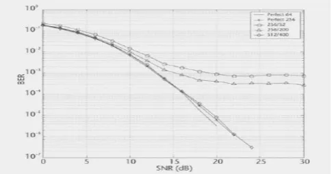
Fig 6: Performance of FFT estimation with higher order OFDM system. [15]
Figure 6 shows the situation when we increase the size of the OFDM system to 256 and 512 points. It can be seen that with a full system, both 64 and 256 point yield the same result. In the case of 256 points, we fine the same improvement in performance, as the number of data carriers is increased from 52 to 200. However, 256/200 is inferior to 64/52 in terms of performance, as can be seen from Figure 4.5 In terms of percentage of used carriers, both are nearly similar. But this argument losses ground when we look at the performance of 512/400 (same percentage). It is nearly perfect. Hence, it is a good idea to use as large a system as possible when using this method of estimation. In a packet system, it is essential that the channel be estimated as correctly as possible in one packet [2].
In figure 6, we plot the behaviour of the system using the synchronization algorithms. The software pertaining to an IEEE 802.11a, the system was modified also to carry out FFT estimation. We only discuss the results here. In this plot, we used two types of estimation techniques –LSE and FFT. We note that there is an error ―floor‖ with the FFT algorithm. This occurs due to the truncation phenomenon. Recall that the FFT
[image:4.595.41.284.309.436.2]algorithm is designed to reduce noise so as to make the channel estimates more accurate. This is done by converting to time domain and truncating at the end of the cyclic prefix. The argument here is that if the cyclic prefix is correctly designed, the entire impulse response of the channel will be confined to within the cyclic prefix. A nothing outside this is noise and can be discarded. When we truncate the time window, and then take the FFT of the result, we retrieve this channel information but with a much reduce noise level. This works fine, as we have seen in Figure 4.6. We now examine the performance during synchronization. During synchronization our endeavor is to synchronize to the start of OFDM symbol. This process of synchronization is carried out based on channel estimation. In IEEE 802.11 a systems, we employ zero padding (64/52). Therefore, the performance is similar to the one in Figure 5, which is not surprising. Therefore, there is an error ―floor‖ at high SNRs. We cannot
Figure 7: Performance of synchronization algorithms using LSE and FFT estimation for a 2×2 system. [16]
get rid of this ―floor‖ because of the nature of the phenomenon and the need for zero padding of the edge subcarriers to avoid ICI. However, we can mitigate it by increasing the number of subcarriers to, say and 512 subcarriers. In such an event we spread this error over a larger number of subcarriers. Another interesting aspect to note is that the SNR is shown varying from 10 dB to 30 dB. Below 10 dB there is no reliable synchronization with either algorithm. We require a basic level of SNR for both the algorithms to works correctly.The algorithm for channel estimation using FFT does have certain disadvantages, but its importance cannot be denied. There are many papers on channel estimation for MIMO systems. But for these algorithms to have practicable value, it is essential that in packet transmission systems, the channel be estimated in one packetand we then use these estimates to recover the transmitted in signal from the rest of the packet, assuming quasi-stationary. Hence, from this point of view the FFT technique performs better than LSE or MMSE.
www.ijsrp.org
We need to improve on the channel estimation technique for MIMO purposes by resorting to analgorithm other thanLSE.The FFT approach is one such. To obtain goodresults usingthe FFT approach, it is necessary to increase the number of subcarriers from the present 64 in IEEE 802.11a and similar system. This will make for better accuracy of channel estimates due to the higher number of points. The side effect of the last point is that the data rate will also increase, bandwidth permitting. This is a welcome development.
REFERENCES
[1] Heiskala, J. and J. Terry, OFDM Wireless LANs : A Theoretical and Practical Guide, Indianapolis, IN : SamsPublishing, 2002.
[2] Mody, A.N. and G.L. Stuber, ‗Synchronization for MIMO-OFDM,‘ IEEE Global Communication Confarence, San Antonio, Texas, November 2001.
[3] OFDM and MC-CDMA by L. Hanzo et.al, IEEE Press, 2003.
[4] Jeffrey H .Reed , Software Radio- A modern approach to radio engineering , Chapter 6 on smart antenna , published by Pearson Education, 2006.
[5] M. Jankiraman, Space –time Codes and MIMO systems, published by Artech House, 2004.
[6] B. Vucetic& J. Yuan, ‗Space Time Coding‘, published by John Wiley&Sons Inc., 2003.
[7] Mody, A.N. and G.L. Stuber, ‗Synchronization for MIMO-OFDM,‘ IEEE VehicularTechnologyConference, Taiwan, 2002.
[8] W. Stallings, ―Wireless communication and networks‖, Pearson Education Asia publication, 2002.
[9] Dr Mostafa HashemSherif ,‖Enterprise
IntegrationHandbook‖ ,Higher Speed Study Group , Page 661 , 2009
[10] WaltenegusDargie, Christian Poellabauer ,‖ Fundamentals of Wireless Sensor Networks: Theory and Practice‖, Page 8, 2010
[11] Prof François Horlin, André Bourdoux ,‖ Digital CompensationforAnalog Front-Ends‖, Page 20, 2008
[12] MohinderJankiraman, ―Space-time Codes And MIMO Systems‖Page256 ,2004
[13] YevgeniKoucheryavy, Jarmo Harju, Villy B. Iversen , ―NextGenerationTeletraffic and Wired/Wireless Advanced Networking‖, Page 483, 2006
[14] Yi Pan, Laurence Tianruo Yang , ―Parallel And DistributedScientific And Engineering Computing:‖, Page 8,2004
[15]MohinderJankiraman , ―Space-time Codes And MIMO Systems‖ - Page 258,2004
[16] Kai Hwang, FayéAlayé Briggs, ―Computer architecture and parallelprocessing‖, 1984
AUTHORS
SudipBandyopadhyay is awarded the degree of M.Tech in Computer Science and Engineering from JIS College of Engineering under West Bengal
University of Technology in
2011.Before that he received MCA degree from NetajiSubhash Engineering College under West Bengal University of Technology in 2004.Before that he has completed BSc. in math (H). He has 3 years Industrial experience in IT industry and more than 3 years teaching experience in Technique Polytechnic Institute as a Lecturer. His research interest includes advanced DBMS, DBMS, System Programming ,Computer Graphics & Software Engineering.
Mr.AnirbanGhosal is awarded the
degree of M.Tech in Mobile
Communication & Network technology from West Bengal University of
Technology (JIS College of
Engineering—The only autonomous engineering college in West Bengal) in 2010. Before that he received the B.Tech degree in Electronics and Communication Engineering Dept. from MCET in 2006. Recently, he is worked as an Assistant professor rank of ECE Dept. in JISCE, Kalyani. Before that,
he workedas Assistant Professor in
BIET(Suri),DIT(Thakurpukur,Behala),GKCEM(Baruipur).He worked as lecturer and HOD in Jiyagang College of Engineering & Technology (Polytechnic). He has been engaged as a successful examiner of WBUT curriculum as well as West Bengal Council of Technical Education. Before worked in educational field, he was engaged in IT and telecom industry. His research interest includes Communication, Digital Simulation etc.
Jayanta Kumar Ray received degree AMIETE from IETE Calcutta Centre. After that he awarded M.Tech in
Electronics and Communication
www.ijsrp.org
Swati Banerjee has received B.Tech degree in Electronics & Communication from Techno India under West Bengal Univesrity of Technology on the year 2006 and completed M.Tech degree in Electronics & Communication from Kalyani Government Engineering College on 2010. She engaged as a Visiting- Lecturer of UG course in Kalyani Government Engineering College, Kalyani ,West Bengal and also in Global Institute of Management &Technology,Krishnagar,West Bengal. Now she is working as an assistant professor of ECE dept. of Narula Institute of Technology,Agarpara,West Bengal. Her main research area includes dexterity control ,signal processing, digital simulation and optimization.
Dr.BiswarupNeogi is awarded his
PhD(Tech) in Jadavpur University, WB, India. HereceivedM.Tech degree in Electronics &CommunicationEngineering from Kalyani Government Engineering College, WB, India in 2007. Before that
He obtained B.E in ECE from
![Figure.2 Performance of 2×2 STBC and SISO in an IEEE 802.11a environment[11]](https://thumb-us.123doks.com/thumbv2/123dok_us/9112546.984779/2.595.308.558.69.242/figure-performance-stbc-siso-ieee-a-environment.webp)
![Figure 4: Comparison of performance, V-BLAST, and STBC in MIMO-OFDM environment [13]](https://thumb-us.123doks.com/thumbv2/123dok_us/9112546.984779/3.595.42.288.69.252/figure-comparison-performance-blast-stbc-mimo-ofdm-environment.webp)