International Journal of Emerging Technology and Advanced Engineering
Website: www.ijetae.com (ISSN 2250-2459, ISO 9001:2008 Certified Journal, Volume 4, Issue 5, May 2014)
727
Palm Vein Identification and Verification System Based on
Spatial Energy Distribution of Wavelet Sub-Bands
Asmaa M.J. Abbas
1, Dr. Loay.E. George
21
Researcher, Department of Computer Science, College of Science, Baghdad University
2Assistant Professor, Head of Department, Department of Computer Science, College of Science, Baghdad University
Abstract—A novel personal verification and identification system using the near-infrared (NIR) images of palm veins patterns is presented in this paper. Anew approach to extract features is proposed depend on the Spatial Energy Distribution of Wavelet Sub-bands. The proposed algorithm focuses on the coefficients' values of the wavelet detail sub-bands (which, mainly reflects the edges' directions distribution in the studies region of interest). The average of the energy distribution of each sub-band is utilized to establish the feature vector. Each wavelet detail sub-band is divided into overlapped blocks, then, the coefficients' average energy is calculated for each block be used as an element in the established feature vector.
The system was tested over a database collected from 250 volunteers, where 24 images are taken for the 2 palms of each person. In total, the whole database contains 6,000 images belong to 500 different palms. The attained recognition rate was excellent (100%) and the achieved minimum equal error rate (EER) is 0.068%with the high matching speed.
Keywords— Palm Recognition, NIR hand palms, Biometrics, Image Representation
.
I. INTRODUCTION
Personal identification and verification are playing a more and more important role in the society. Traditional authentication method, such as password and smart card, often cannot meet today’s security requirements, as they can be easily forgotten, lost or stolen. Today, a person’s identity is recognizable with high confidence using biometrics-based personal identification which appeared as a new solution to these problems [1]. A large range of biometric authentication methods is available, including methods based on the recognition of the fingerprint, retina, iris, face, palm geometry, palm print, DNA, hand vein, finger vein, signature, voice, typing rhythm, and gait, to name a few. Each method has its own advantages and disadvantages, but none of them is ideal[2].
Hand vein patterns are the vast network of blood vessels underneath a person’s skin. The vein patterns are unique, and are stable over a long period of time. Also, they are invisible to human eye, and not significantly affected by external distortions.
It is not easy to replicate the vein patterns as compared to other biometric traits[3]. Hence vein recognition is becoming one of the most reliable member of biometric family and has attracted extensive interests from the biometric researchers [4].
In the palm vein recognition system, the vascular pattern of an individual’s palm is used as personal identification data. Each palm has complicated vascular pattern and thus it shows a wealth of differentiating features for personal identification. The palm is an ideal part of the human body in biometric technology; normally it does not have hair which can be an obstacle for photographing the blood vessel pattern, and it is less susceptible to a change in skin color, unlike a finger or the back of a hand [5].
II. RELATED WORK
International Journal of Emerging Technology and Advanced Engineering
Website: www.ijetae.com (ISSN 2250-2459, ISO 9001:2008 Certified Journal, Volume 4, Issue 5, May 2014)
728
III. PROPOSED SYSTEM
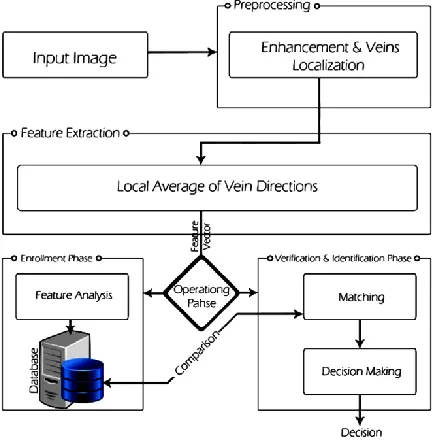
In this paper a palm vein recognition and verification system is presented. The system work flow passes through two main phases: (i) the enrollment phase and (ii) the identification &verification phase. In the enrollment phase, the biometric system is trained to the identity of each person through its discriminating features. While in the cognition phase the system works either as identification process (which identify who the person is?)or as verification process (which verify that a person is who he/she claims to be). The layout of the proposed system is shown in Figure(1); it consists of three modules: (i) enhancement and vein localization, (ii) feature extraction using Spatial Energy Distribution of Wavelet Sub-bands, and (iii) matching stage using similarity measures.
A. Preprocessing Stage
[image:2.612.60.278.432.652.2]The imaging quality and variability of the vein images acquired by the near-infrared (NIR) device present many challenges to achieve high classification accuracy. In the proposed system, the first step is image enhancement, then the localization of veins grid; which is the region of interest (ROI). In this module the preprocessing stages presented in [10] have been applied on the NIR palm images; this applied module consists of the stages:
Figure 1. The general structure of the proposed system
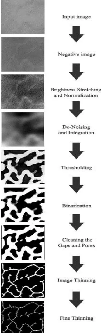
Enhancement of the input image: it includes three stages: (i) image preparation, (ii) brightness stretching & normalization, (iii) de-noising and integration.
Segmentation of the vein grid: it includes two stages: (ii) thresholding, and (ii) binarization.
Post-processing stage: It is needed to enhance the extracted vein grid after segmentation. It includes the sub-stages: (i) cleaning of gaps and pores, (ii) coarse thinning, and (iii) fine thinning. The last sub-stage consists of three steps: (a) integration, (b) edge normalization, and (c) binarization with thinning).
Figure(2) presents an illustration for the preprocessing stage and the result of each sub-stage.
B. Feature Extraction
In order to provide accurate recognition of individuals, the most discriminating information representing the view pattern must be extracted. The extracted representing information is gathered in a features vector to distinguish the person from others.
In this work, the extracted discriminating information is the "Spatial Energy Distribution of Wavelet Sub-bands"; each extracted feature vector is saved in a database or sent to matching stage for recognition purpose.
In our proposed recognition system, discrete Haar wavelet DHW is chosen for many reasons: (i) representing the vein image into another domain that can reflect the vein structure directionality and density at different scales, (ii) each wavelet (detail) sub-bands holds certain type of edges (i.e., horizontal, vertical or diagonal edges), and (iii) Haar wavelet transform has low computational cost in comparison with other types transforms.
To extract this wavelet based set of features from a vein image the following steps have been applied:
To apply Haar transform on a complete image, partition the image into blocks of 2x2 pixels, then apply the method [11] on each group. To show more clearly the transform steps consider a small 2x2 sub-image that can represented by the matrix s of the form:
d c b a s
Then, when it is Haar transformed (i.e., by multiplying it by T) then the following output will result:
International Journal of Emerging Technology and Advanced Engineering
Website: www.ijetae.com (ISSN 2250-2459, ISO 9001:2008 Certified Journal, Volume 4, Issue 5, May 2014)
729
Figure 2. Illustration for the outcomes of preprocessing stage
[image:3.612.85.251.145.691.2]After applying the 2-DDHW on the image, for one level, it is decomposed into four sub-bands (i.e., LL, LH, HL, and HH), which correspond to approximate, horizontal, vertical, and diagonal image components, respectively. Figure (3) illustrates the sub-bands labeling depending on their contents.
Figure 3. The approximation (A) & details sub-bands (H,V,D)
The sub-band (A) is approximately half the original image. While the sub-bands H, V and D contain the local changes of images (i.e., including edges) along the Horizontal, Vertical and Diagonal directions, respectively. Figure (4) shows a vein image and its corresponding Haar wavelet transform.
The proposed system focuses on the values of transformed coefficients of the detail sub-bands (which, mainly depends on the edges directions). The spatial distribution of the average energy of each sub-band is utilized to establish the feature vector. The feature set was not extracted directly from these sub-bands; the following steps have been followed to extract the set of features:
[image:3.612.391.498.209.308.2](a) (b)
Figure 4. Vein image (a) Original image (b) Its 2D DHW transform
[image:3.612.336.551.479.593.2]International Journal of Emerging Technology and Advanced Engineering
Website: www.ijetae.com (ISSN 2250-2459, ISO 9001:2008 Certified Journal, Volume 4, Issue 5, May 2014)
730
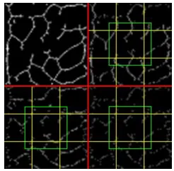
Figure (5) illustrates the sub-bands after dividing them into overlapped blocks.
Figure 5. Partitioning sub-bandto overlapping blocks
The average energy of each block is calculated. The average energy is computed by dividing the summation of square values of the non-zero wavelet coefficients, belong to the block, by the number of coefficients, that is:
y x p
p w x y
N
D 1 2( , )
,…..(2) Where, Dpis the local energy average for the block, w(x,y)is the DHW coefficient and Np is the number of pixels belong to the block.
Now, after the calculation of coefficients' average energy for each block, then the list average energies of all blocks is assembled in a feature vector V:
V() = [DpH(), DpV(), DpD()]
Where DpH(), DpV(), and DpD() are the energy distribution vectors for the horizontal (LH), vertical (HL) and diagonal (HH) sub-bans, respectively. The three extracted vectors DpH(), DpV()&DpH() are sequentially concatenated to construct the feature vector V().
C. Palm Vein Matching Stage
For matching criteria the two well-known similarity measures (i.e., Euclidean distance which is the mean square difference between a template and an input pattern; and the mean absolute difference; called city block distance) have been used.
IV. EXPERIMENTAL RESULTS
The performance of the proposed system was tested using the samples of PolyU multi-spectral palm print database[12].It consists of NIR palm samples collected from 250 volunteers, including 195 males and 55 females. The age distribution of volunteers is from 17 to 60 years. The samples have been collected through two separate sessions. In each session, the subject was asked to provide 6 images for each palm. Therefore, 24 images for each volunteer were collected, 12 of them for each of his/her 2 palms. In total, the database consists of 6000 images taken from 500 different palms. The average time interval between the first and the second sessions was about 9 days.
The results of the conducted tests are described in details in the following subsections.
A. Identification (Recognition) Results
The identification system performance is measured using the parameter correct recognition rate (CRR); it is the ratio of the number of samples being correctly classified to the total number of tested samples.
There is a set of system parameters that affect the recognition performance behavior, the main affective ones are:
The number of blocks (ROI divided into NxN blocks).
The ratio of overlapping.
The selected detail sub-bands (H&V&D, H&V, H&D, V&D, H, V, D).
The number of decomposition levels of the applied Haar wavelet.
[image:4.612.106.229.162.283.2]International Journal of Emerging Technology and Advanced Engineering
Website: www.ijetae.com (ISSN 2250-2459, ISO 9001:2008 Certified Journal, Volume 4, Issue 5, May 2014)
731
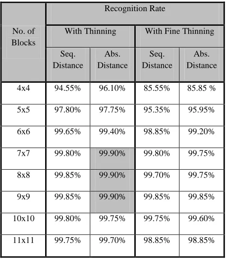
TABLEI
The effect of number of blocks parameter on the recognition rate (when using the sub-bands {H,V,D}& overlapping ratio=0)
No. of Blocks
Recognition Rate
With Thinning With Fine Thinning
Seq. Distance
Abs. Distance
Seq. Distance
Abs. Distance
4x4 94.55% 96.10% 85.55% 85.85 %
5x5 97.80% 97.75% 95.35% 95.95%
6x6 99.65% 99.40% 98.85% 99.20%
7x7 99.80% 99.90% 99.80% 99.75%
8x8 99.85% 99.90% 99.70% 99.75%
9x9 99.85% 99.90% 99.85% 99.85%
10x10 99.80% 99.75% 99.75% 99.60%
11x11 99.75% 99.70% 98.85% 98.85%
Table (I) indicates that the recognition rate is better for the case of not applying fine thinning stage (i.e., depending on the coarse thinning step only); in other words there is no need to add additional thinning stage. Also, the results refer that best recognition rate is attained when the number of blocks is taken (9x9,8x8, or 7x7).
Table (II) lists the recognition rate values when two decomposition levels of Haar wavelet are applied with coarse thinning only and the overlapping ratio is set 0.
TABLEII
THE RECOGNITION RATE FOR THE SEDWS USING TWO DECOMPOSITION LEVELS (OVERLAPPING RATIO=0, SUB-BANDS ARE
{H+V+D})
No. of Blocks
Recognition Rate
Seq. Distance Abs. Distance
5x5 99.30% 99.30%
6x6 99.60% 99.45%
7x7 99.40% 99.35%
8x8 99.50% 99.45%
9x9 99.85% 99.95%
10x10 99.40% 99.50%
The comparison between the results listed in tables (I) and (II) shows that the recognition rate is slightly changed (i.e., %0.05) when the number of decomposition levels is increased. So, there is no need to apply two decomposition levels to extract features due to preservation of processing time.
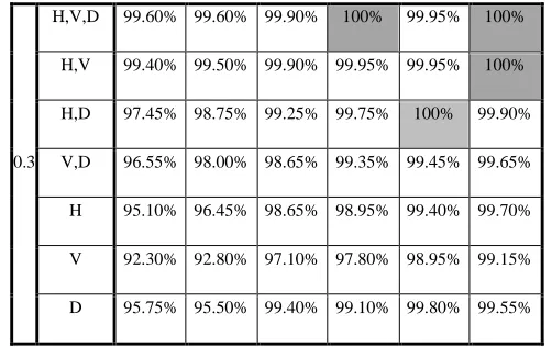
Table (III) reflects the recognition behavior when the discriminating features are extracted from different sub-bands, for different values of overlapping ratio (R), for the best values of block numbers (i.e.,7x7,8x8,9x9) and for one decomposition level. The best attained recognition rate (i.e.,100%) was met when number of blocks is set to (8x8 or 9x9) and overlapping ratio is taken (0.2 or 0.3).
B. Verification (Authentication)
[image:5.612.52.285.167.434.2]International Journal of Emerging Technology and Advanced Engineering
Website: www.ijetae.com (ISSN 2250-2459, ISO 9001:2008 Certified Journal, Volume 4, Issue 5, May 2014)
732
TABLEIII
THE RECOGNITION RATES FOR DIFFERENT COMBINATIONS OF SUB
-BANDS AND DIFFERENT VALUES OF OVERLAPPING RATIO (R)(THE NUMBER OF BLOCKS WAS SET 7X7,8X8,9X9)
R
Sub-bands
No. of Blocks
7x7 8x8 9x9
Seq. Dist.
Abs. Dist.
Seq. Dist.
Abs. Dist.
Seq. Dist.
Abs. Dist.
0
H,V,D 99.80% 99.90% 99.85% 99.90% 99.85% 99.90%
H,V 99.80% 99.90% 99.85% 99.85% 99.85% 99.90%
H,D 99.75% 99.80% 99.75% 99.90% 99.95% 99.95%
V,D 97.60% 98.75% 98.15% 99.35% 98.95% 99.65%
H 98.75% 99.05% 99.35% 99.50% 99.50% 99.65%
V 95.60% 96.05% 96.85% 97.75% 98.25% 98.95%
D 99.15% 98.80% 99.30% 99.35% 99.70% 99.65%
0.1
H,V,D 99.90% 99.95% 99.90% 99.95% 99.95% 99.95%
H,V 99.85% 99.85% 99.85% 99.95% 99.95% 99.95%
H,D 99.10% 99.45% 99.60% 99.95% 99.90% 99.95%
V,D 98.65% 99.30% 99.05% 99.55% 99.55% 99.75%
H 98.15% 98.80% 99.15% 99.55% 99.45% 99.75%
V 96.65% 97.45% 97.75% 98.20% 99.15% 99.30%
D 99.15% 98.75% 99.20% 99.40% 99.80% 99.70%
0.2
H,V,D 99.85% 99.90% 99.90% 100% 99.95% 99.95%
H,V 99.80% 99.75% 99.90% 99.95% 99.95% 99.95%
H,D 98.20% 99.60% 99.25% 99.75% 99.95% 99.90%
V,D 98.15% 99.15% 98.65% 99.35% 99.55% 99.75%
H 97.10% 97.90% 98.65% 98.95% 99.45% 99.75%
V 95.75% 96.05% 97.10% 97.80% 99.15% 99.30%
D 98.20% 97.70% 99.40% 99.10% 99.80% 99.70%
0.3
H,V,D 99.60% 99.60% 99.90% 100% 99.95% 100%
H,V 99.40% 99.50% 99.90% 99.95% 99.95% 100%
H,D 97.45% 98.75% 99.25% 99.75% 100% 99.90%
V,D 96.55% 98.00% 98.65% 99.35% 99.45% 99.65%
H 95.10% 96.45% 98.65% 98.95% 99.40% 99.70%
V 92.30% 92.80% 97.10% 97.80% 98.95% 99.15%
D 95.75% 95.50% 99.40% 99.10% 99.80% 99.55%
This is based on the rationale that both rates must be as low as possible for the biometric system to work effectively [13].
The FAR and FRR are defined, respectively, as[14]:
FRR =
FAR =
Also the performance of biometric systems can be measured by accuracy (i.e.,the proportion of correct predictions) without considering what is positive (P) and what is negative (N) [15].
Accuracy=(TP+TN) / (P+N)
[image:6.612.318.569.134.292.2]International Journal of Emerging Technology and Advanced Engineering
Website: www.ijetae.com (ISSN 2250-2459, ISO 9001:2008 Certified Journal, Volume 4, Issue 5, May 2014)
733
TABLEIV
FAR,FRR AND ACCURACY VERSUS DIFFERENT THRESHOLD
No. of Blocks Threshold FRR% FAR% Accuracy%
8x8
0.08 3.1 0.00025 99.997
0.085 1 0.0023 99.997
0.09 0.2 0.015 99.984
0.095 0.05 0.09 99.909
0.1 0 0.43 99.570
9x9
0.08 3.4 0.00041 99.9961
0.085 1.35 0.0017 99.992
0.09 0.45 0.0115 99.988
0.095 0.1 0.0687 99.931
0.1 0 0.3054 99.694
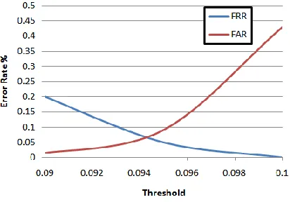
The ROC curve between the FAR and FRR with various thresholds is plotted in Figures(6) and (7).The equal error rate is 0.068%,0.082% for the threshold value equal to 0.0943,0.0954,when the number of blocks is set8x8 and 9x9, respectively.
[image:7.612.338.544.121.283.2]Figure 6. The ROC curve for 8x8 blocks number
Figure 7. The ROC curve for 9x9 blocks number
C. Time Results
Beside recognition rate the second adopted performance indicator is the processing time. The recognition time is the overall required time to perform preprocessing, feature extraction, and matching tasks. Tables (V), (VI) and (VII) present the effects of different system parameters on the recognition time.
TABLEV
THE MEAN PROCESSING TIME OF THE PREPROCESSING STAGE
Preprocessing Time (in milliseconds)
Using only Coarse Thinning 1.483
TABLEVI
THE MEAN PROCESSING TIME FOR FEATURE EXTRACTION AND MATCHING STAGES VERSUS THE NUMBER OF BLOCKS (DATABASE SIZE =
500 PALMS)
No. of Blocks
Time (in milliseconds)
SEDWS (three sub-bands) Feature
[image:7.612.66.272.491.635.2]International Journal of Emerging Technology and Advanced Engineering
Website: www.ijetae.com (ISSN 2250-2459, ISO 9001:2008 Certified Journal, Volume 4, Issue 5, May 2014)
734
TABLEVII
THE MEAN PROCESSING TIME OF THE FEATURE EXTRACTION AND MATCHING STAGES (THE SUB-BANDS={H+V+D}; THE NUMBER OF
BLOCKS IS 9X9)
Sub-bands
Time(in milliseconds)
Feature
Extraction Matching
3 168.332 114.03
2 165.247 77.082
1 162.388 40.267
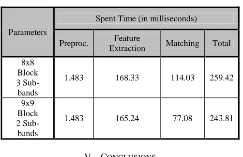
Table (VIII) lists the details of spend time for the best attained recognition results for the best two cases of features sets.
TABLEVIII EXECUTION TIME
Parameters
Spent Time (in milliseconds)
Preproc. Feature
Extraction Matching Total 8x8
Block 3 Sub-bands
1.483 168.33 114.03 259.42
9x9 Block 2 Sub-bands
1.483 165.24 77.08 243.81
V. CONCLUSIONS
In this paper, we proposed a novel personal verification and identification system based on the vein-patterns of palm veins. A new feature set is proposed in this work; it depends on the "Spatial Energy Distribution of Wavelet Sub-bands".
The experimental results show that our system achieved high recognition rate100%, and EER equal to 0.068%, which indicate high performance in verification. These results indicate that the proposed method can achieve high performance comparable with other related work [5] [6] [7] [8] [9] [10]. The total recognition time is around 0.159second; which is fast enough for real time applications.
REFERENCES
[1] Fang, L.;Lingyu, W.; and Ying,H.;"Vein Identification Using Line Features", IEEE, 2012.
[2] Sato, Y.;Akazawa, F.;Muramatsu, D.; Matsumoto, T.; Nakamura A.;
and Sota, T.;"An Authentication Method by High Spectral Resolution Palm Data Cube", International Conference on Biometrics and Kansei Engineering, Pp. 293-244, IEEE, 2013.
[3] Pal, M.M.;JasutkarR.W.; "Implementation of Hand Vein Structure
Authentication Based System", International Conference on Communication Systems and Network Technologies, Pp. 114-118 , IEEE, 2012.
[4] Wu, X.;Gao, E.; Tang, Y.; and Wang, K.;"A Novel Biometric
System Based on Hand Vein", Fifth International Conference on Frontier of Computer Science and Technology, Pp. 522-526, IEEE, 2010.
[5] Zhang, H.; Hu, D.;"A Palm Vein Recognition System", IEEE, 2010.
[6] Soni, M.; Gupta, S.;Rao, M.S.; and Gupta, P., "An Efficient Vein
Pattern-Based Recognition System", Fourth International
Conference on Emerging Security Information, Systems and Technologies, Pp. 234-239, IEEE, 2010.
[7] Wang, Y.; Li, K.; Shark, L.K.; and Varley, M. R.;"Hand-dorsa Vein
Recognition Based on Coded and Weighted Partition Local Binary Patterns", IEEE, 2011.
[8] Tang, Y.; Huang, D.; and Wang Y.;"Hand-Dorsa Vein Recognition
Based on Multi-level Keypoint Detection and Local Feature Matching”, 21st International Conference on Pattern Recognition (ICPR), Pp. 2837-2840, 2012.
[9] Prabu, S.M.;Sivanandam, S.N.;"A Novel Biometric system for
Person Recognition Using Palm vein Images", International Journal on Computer Science and Engineering (IJCSE), Vol. 5, No. 8, August 2013.
[10] Abbas, A. M. J.; George, L. E.;” Palm Vein Recognition and
Verification System Using Local Average of Vein Direction”, International Journal of Scientific and Engineering Reseaech (IJSER), Volume 5, Issue 4, Pp 1026-1033, 2014.
[11] Gavlasová, A.; Procházka, A.; and Mudrova, M.; "Wavelet Based
Image Segmentation” , In Proc. of the 14th Annual Conference Technical Computing, Prague, 2006.
[12] Multispectral PolyU database,
ww4.comp.polyu.edu.hk/~biometrics/.
[13] Yazdani, Ma.; and Moayycxii, F.;"Palmprint Authentication Based on HOG and Kullback Leibler”, Proceedings of the Third International Conference on Contemporary Issues in Computer and Information Sciences”, Can Stock Phoro, Inc., Pp.370-373 , 2012.
[14] Merouane, A.;Benziane, S.;Boulet, P.;Benyamina, A. E. H.;Loukil,
L.;"Hybridization of Discrete Binary Particle Swarm Optimization and Invariant Moments for Dorsal Hand Vein Feature Selection", IEEE, 2013.
[image:8.612.58.280.167.280.2] [image:8.612.44.295.344.506.2]