International Journal of Emerging Technology and Advanced Engineering
Website: www.ijetae.com (ISSN 2250-2459, ISO 9001:2008 Certified Journal, Volume 4, Issue 2, February 2014)
911
A Review of Cordic Algorithm in DDS Based
Communication Systems
Godbole B. B.
1, Nikam R.H.
2, Pandit M.D.
31
Department of Electronics, K.B.P College Of Engineering Satara, Shivaji University Kolhapur, Maharashtra, India 2,3PG student with Department Of Electronics, K.B.P. College Of Engineering Satara, Shivaji University, Kolhapur,
Maharashtra,India
Abstract-- Direct digital synthesis (DDS) is a method to generate waveforms directly in the digital domain. In this method,the target waveforms are the sine and cosine ones. The Co-ordinate Rotational Digital Computer (CORDIC) algorithm configured in Rotation Mode (RM) can behave as a quadrature phase-to-amplitude converter that directly generates sine and cosine waveforms. The main advantage of using CORDIC-based DDS with respect to Look Up Table (LUT) based methods is that it can achieve both high phase resolution and high precision with lower hardware cost. CORDIC algorithm is a unique technique for performing various complex arithmetic functions using shift-add iterations. This paper reviews the use CORDIC architectures and types along with Direct Digital Synthesis to implement both analog and digital modulation techniques that can be found in a software defined radios i.e. reconfigurable digital radios. Also this system found in many modern devices, including radio receivers, mobile telephones, radiotelephones, walkie-talkies, satellite receivers, GPS systems, etc.
Index Terms-- CORDIC Algorithm, CORDIC Architectures, DDS, Communication System.
I. INTRODUCTION
The Coordinate Rotation Digital Computer (CORDIC) was introduced in 1959 by Volder [1]. It is an easy-to-implement and versatile algorithm widely used for digital signal processing applications. It computes iteratively the rotation of a two-dimensional vector using only add and shift operations. CORDIC has been traditionally used for hardware implementations. In [2] several algorithms which admit efficient implementation using CORDIC were reviewed: linear transforms, digital filtering, and matrix based DSP computing algorithms. It was shown that CORDIC-based architectures are a very appealing alternative to conventional multiply-and-add hardware. However, CORDIC may be also applied to implement different communication subsystems found in a digital radio: direct digital synthesizers; amplitude shift keying (ASK), phase shift keying (PSK), and frequency shift keying (FSK) modulators.
II. CORDIC FUNDAMENTALS
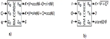
For an easy understanding of how to use the CORDIC algorithm in the implementation of digital intermediate frequency (IF) communications systems, CORDIC is presented only as a computational resource with three inputs (X0, Y0, and Z0) and three outputs (XN, YN, and ZN)
that allows performing the following operations[3]as shown in Figure 1.
• Rotation Mode (RM): Rotation of a vector (I, Q) by an angle q when it is operating in rotation mode (RM); the rotated output vector is multiplied by a constant value K.
• Vectoring Mode (VM): Cartesian-to-polar conversion, when it is operating in vectoring mode (VM); the modulus of the vector is also scaled by K.
A generic scheme that shows how to use RM CORDIC to implement different digital communication tasks is shown in Figure1. The scheme is composed of an RM CORDIC where signals I and Q are connected into
X0 and Y0inputs, and the phase term q connected into Z0
input is This phase term is composed of the accumulation, at a sample period of Ts, of two frequency terms, fc and fm, and a phase term,
Øm The additions involved in its computation are signed
modulo-1 (limited to the interval [–1,1]), and the frequency and phase terms fc, fm and Øm are normalized to
1. The CORDIC Z0 input needs a phase input that takes
values in the interval [–π, π], so a multiplication by π is required to extend the interval of the normalized term q to the interval required by CORDIC [3].
[image:1.595.335.519.608.673.2]International Journal of Emerging Technology and Advanced Engineering
Website: www.ijetae.com (ISSN 2250-2459, ISO 9001:2008 Certified Journal, Volume 4, Issue 2, February 2014)
912
CORDIC computes a pseudo-rotation of a two-dimensional vector instead of perfect rotation. This means that the original vector is rotated by an angle q, and its magnitude is enlarged by a constant factor K.
The CORDIC algorithm iteratively computes the pseudo-rotation by an angle q with the following iterations:
Xi+1 = [Xi– di× 2–i× Yi]
Yi+1=[Yi+di×2–i×Xi] (1) Zi+1 = Zi– di× ai
Instead of directly performing a rotation by the angle q, CORDIC performs several micro-rotations by the angles ai=±atan (2–i). This means that the rotation angle q
is broken down into a set of predefined angles ai, so after
a number of iterations the angle q is approximated by ∑ (di× ai), where di belongs to the set {–1, 1}. CORDIC Eq.
(1) admits two operating modes, the rotation mode (RM) and the vectoring mode (VM), which depend on how the directions of the micro rotations (di) are chosen: di= sign
(Zi) for RM and di= –sign (Yi) for VM.
III. DIFFERENT ARCHITECTURES OF CORDIC
In general, CORDIC architectures can be broadly classified as folded and unfolded, based upon the hardware realization of the three iterative equations [4]-[6]. A direct duplication of equation (1) into hardware results in folded architecture. Folded architectures have to be multiplexed in time domain so that all the iterations are carried out in a single functional unit. This provides a means for trading area for speed [7] in signal processing architectures. One of the widely used folded architectures is implementing the entire CORDIC core using a word serial design.
A. Folded word serial design:
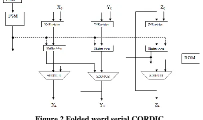
[image:2.595.64.268.614.734.2]A folded word serial design [8], also called iterative bit-parallel design is obtained simply by duplicating each of thethree difference equations in hardware as shown in Figure 2.
Figure 2 Folded word serial CORDIC
Being a shift-add algorithm, each individual unit consists of an adder/subtractor unit, a shifter and a register for holding the computed values after each iteration.
To start with, the initial values are fed into each branch via a multiplexer. The value in the z branch determines the operation of the adder-subtractor unit. Signals in the x and y branch pass through the shifter units and are then added to (or subtracted from) the unshifted signal in the opposite path. The z branch arithmetically combines the register values with the values taken from a lookup table whose address is changed according to the number of iteration. The result of this operation determines the nature of operation for the next iteration. After n iterations the results are directly read from the adder/subtractor units. A finite state machine is used to keep a track of shifting distances and the ROM addresses. Since the adder/subtractor unit and the shifters in each path are shared on time basis, this conventional approach of implementing the CORDIC algorithm is not suitable for high speed applications [8]. Another disadvantage is with respect to the shift operations. When implemented in hardware the shifters have to change the shift distance with the number of iteration. For large number of iterations these require a high fan in and reduce the maximum speed for the application. These shifters do not map well into FPGA architectures and if implemented require several layers of logic. The result is a slow design that uses large number of logic cells. In addition the output rate is also limited by the fact that the operation is performed iteratively and therefore the maximum output rate equals 1/n times the clock rate, where n is the number of iterations.
B. Unfolded parallel design:
International Journal of Emerging Technology and Advanced Engineering
Website: www.ijetae.com (ISSN 2250-2459, ISO 9001:2008 Certified Journal, Volume 4, Issue 2, February 2014)
[image:3.595.66.265.140.358.2]913
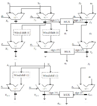
Figure 3 Unfolded CORDIC designIn the case of most FPGA architectures there are already registers present in each logic cell, so the addition of the pipeline registers has no additional hardware cost.
IV. COMPARISON OF CORDIC ARCHITECTURES
The folded and unfolded structures are compared for different performance parameters. Table 1 provides latency comparison for 16 and 32-BIT CORDIC structures. Table 2 gives the maximum operating frequency comparison of the folded, unfolded and pipelined structures for word lengths of 16 and 32 bits.
TABLE 1
LATENCY COMPARISON FOR16 AND 32-BIT CORDIC
Parameter
CORDIC architecture
Folded Unfolded Word Length
(Bits) 16 32 16 32
Logic delay
(ns) 5.59 6.959 5.804 9.18 Route delay
(ns) 22.023 33.071 18.69 25.0 Max
Combinational delay (ns)
33.078 42.414 24.472 34.2
It is observed that when timing response of the CORDIC structures is concerned, the unfolded architecture has less worst-case delay compared to that for folded structure. This is due to the unfolding process which eliminates the use of storage registers and thus the corresponding set-up and hold times.
[image:3.595.323.541.248.389.2]The overall latency is thus reduced by a factor proportional to these set-up and hold times. Note, however that the maximum operating frequency and thus the throughput of the unfolded CORDIC is determined by the worst case delay of the structure. This is because the structure is purely combinatorial. Contrast to this, the folded structure can be clocked at high frequencies resulting in large operating frequencies.
TABLE 2
THROUGHOUT COMPARISON FOR16 AND 32-BIT CORDIC.
Parameter
CORDIC architecture
Folded Unfolded (Parallel)
Unfolded (Pipelined) Word
Length (Bits)
16 32 16 32 16 32 Max.
Operating Frequency (MHz)
216 125 44 31 232 163
[image:3.595.309.554.531.758.2]Pipelined unfolded CORDIC architecture processes multiple inputs simultaneously. This increases the maximum operating frequency of the unfolded structures. For an N-stage CORDIC core, N-stage pipeline can give the best results. The first output of an N-stage pipelined CORDIC core is obtained after N-clock cycles. Thereafter, outputs will be generated after every clock cycle. Further analysis of CORDIC is carried out by comparing the power consumption for 32 bit word length. Table 3 gives the power consumption for the three structures.
TABLE 3
POWER COMPARISONS FOR 32-BIT CORDIC ARCHITECTURES
Resource
CORDIC architecture
Folded Unfolded (Parallel)
Folded (Pipelined) Power (Clock)
(mW) 21.33 -- 17075
Power (Logic)
(mW) 2.15 13.87 9.20
Power (Signals)
(mW) 15.71 11.01 12.33
Power (IOs)
(mW) 93.60 196.07 196.64 Power
(leakage/quiescent) (mW)
380.99 382.30 382.21 Dynamic power
(mW) 132.78 220.95 235.92 Total power
International Journal of Emerging Technology and Advanced Engineering
Website: www.ijetae.com (ISSN 2250-2459, ISO 9001:2008 Certified Journal, Volume 4, Issue 2, February 2014)
914
Folded structures have less power dissipation compared to the parallel and pipelined unfolded structures. The power consumed by logical components in case of folded structures is quite low.
[image:4.595.330.529.172.230.2]This is due to the fact that the folded structure uses the same components repetitively. Similarly due to the multiple input/output instantiations in unfolded structures the power consumed by the input and output resources is quite high; resulting in high dynamic power dissipation in the parallel and pipelined designs. Finally, the three designs are analyzed for area consumption in terms of resource utilization and the results are tabulated in Table 4. As the folded structure is an efficient user of logic, the same logical units are used in all iterations. But since the result needs to be fed back after each iteration large number of registers are used in the folded word serial implementation
.
TABLE 4
AREA COMPARISON FOR 32-BIT CORDIC
Parameter CORDIC architecture Folded Unfol
ded (Parall
el)
Folded (Pipelin ed) No. of Registers 768 -- 678 No. of LUTs 287 1093 1006 No. of Logic blocks used 285 1093 1006 No. of occupied slices 121 589 336 No. of LUT Flip-Flop
pairs used
768 1093 1013 No. of bonded IOBs 193 193 194
V. APPLICATIONS TO COMMUNICATION SYSTEM
CORDIC algorithm can be used for efficient implementationof various functional modules in a digital
communication system.Most applications of CORDIC in
communications use the circular coordinate system in one or both CORDIC operating modes. The RM-CORDIC is mainly used to generate mixed signals, while the VM-CORDIC is mainly used to estimate phase and frequency parameters. We briefly outline here some of the important communication applications.
A) Direct Digital Synthesis:
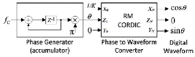
Direct digital synthesis [10], [11] is the process of generating sinusoidal waveforms directly in the digital domain. A direct digital synthesizer (DDS) consists of a phase accumulator and a phase-to-waveform converter [12]. The phase-generation circuit increments the phase according to ∑fc and feeds the phase information to
the phase-to-waveform converter, where fc is the
normalized carrier frequency in every cycle. The phase-to-waveform converter could be realized by an RM-CORDIC [3], [13], as shown in Figure 4.
The cosine and sine waveforms are obtained respectively by the CORDIC outputs XN and YN.
Figure 4 CORDIC-based Direct Digital Synthesizer = ∑ fc .
B) Analog and Digital Modulation:
A generic scheme to use CORDIC in RM for digital modulation is shown in Figure 5, where the phase-generation unit of Figure 5 is changed to generate the
phase according to π , for
and being the normalized carrier and the modulating
frequencies respectively, and is the phase of
[image:4.595.54.275.345.514.2]modulating component.
Figure 5 A generic scheme to use RM CORDIC for digital modulation. I and Q are, respectively, the in-phase and quadrature
signals to be modulated.
By suitable selection of the parameters and and the CORDIC inputs X0 and Y0, the generic scheme of
Figure 5 it could be used for digital realization [14]-[16] of analog amplitude modulation (AM), phase modulation (PM), and frequency modulation (FM), as well as the digital modulations, e.g., amplitude shift keying (ASK), phase-shift keying (PSK), and frequency- shift keying (FSK) modulators. It could also be used for the up/down converters for quadrature-amplitude modulators (QAM) [17] and full mixers for complex signals or phase and frequency corrector circuits for synchronization.
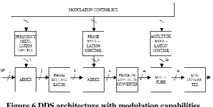
C) DDS Architecture for Modulation Capability:
It is simple to add modulation capabilities to the DDS, because the DDS is a digital signal processing device. In the DDS it is possible to modulate numerically all three waveform parameters [18].
(2)
Where, A(n) is the amplitude modulation ∆P(n) is the frequency modulation, and P(n) is the phase modulation. All known modulation techniques use one, two or all
three basic modulation types simultaneously.
[image:4.595.330.534.361.431.2]International Journal of Emerging Technology and Advanced Engineering
Website: www.ijetae.com (ISSN 2250-2459, ISO 9001:2008 Certified Journal, Volume 4, Issue 2, February 2014)
915
[image:5.595.62.270.222.327.2]The frequency modulation is made possible by placing an adder before the phase accumulator. The phase modulation requires an adder between the phase accumulator and the phase to amplitude converter. The amplitude modulation is implemented by inserting a multiplier between the phase to amplitude converter and the D/A-converter.
Figure 6 DDS architecture with modulation capabilities.
The multiplier adjusts the digital amplitude word applied to the converter. Also, with some D/A-converters it is possible to provide an accurate analog amplitude control by varying a control voltage [19].
VI. CONCLUSION
The beauty of CORDIC is its potential for unified solution for a large set of computational tasks involving the evaluation of trigonometric and transcendental functions, calculation of multiplication, division, square-root and logarithm, solution of linear systems etc. Moreover, CORDIC is implemented by a simple hardware through repeated shift-add operations. This
paper reviews CORDIC architectures and its
comparisons for parameters like operating frequency, latency, power consumption and area occupied. As the result of this comparison, though folded structure consumes less power and it requires less area, for high speed applications it is not feasible architecture hence unfolded architecture is used for high speed applications. The features of CORDIC has made it an attractive choice for a wide variety of applications in communication system as in Direct Digital synthesizer; Analog and Digital modulation subsystems.
REFERENCES
[1] J. E. Volder, ―The CORDIC trigonometric computing technique,‖ IRE Trans. Electronic Computing, volume EC-8, pp 330 – 334, 1959.
[2] Pramod K. Meher, Javier Valls,Tso-Bing Juang, K. Sridharanand KoushikMaharatna ―50 Years of CORDIC: Algorithms, Architectures, and Applications‖ Ieee Transactions On Circuits And Systems—I: Regular Papers, Vol. 56, No. 9, pp 1893-1907,September 2009
[3] J. Valls, T. Sansaloni, A. Perez-Pascual, V. Torres, and V. Almenar, ―The use of CORDIC in software defined radios: A tutorial,‖ IEEE Commun. Mag., vol. 44, no. 9, 2006.
[4] Y.H. Hu, ―Pipelined CORDIC architecture for the implementation of rotational based algorithm,‖ in Proceedings of the International Symposium on VLSI Technology, Systems and Applications, p. 259, May 1985.
[5] R.Andraka, ―A survey of CORDIC algorithms for FPGA based computers, Proceedings of ACM/SIGDA sixth International Symposium on field Programmable Gate Arrays‖, 1998,pp.191-200
[6] J. E. Meggitt, ―Pseudo division and pseudo multiplication processes,‖ IBM Journal, vol. 6, no. 2, pp. 210–226, 1962. [7] C.H.Lin and A.Y. Wu, ―Algorithm and Architecture for
High-Performance Vector Rotational DSP Applications,‖ Regular IEEE Transactions: Circuits and Systems I, Volume 52, pp 2385- 2398, November 2005.
[8] J.S. Walther, ―A unified algorithm for elementary functions,‖ Proc. Spring. Joint Comp. Conf., vol. 38, pp. 379-385, 1971. [9] M.D. Erecegovac and T. Lang, Digital Arithmetic, Elsevier,
Amsterdam, the Netherlands, 2004.
[10] L. Cordesses, ―Direct digital synthesis: A tool for periodic wave generation (part 1),‖ IEEE Signal Process. Mag., vol. 21, no. 4, 2004.
[11] J. Vankka ―Digital Synthesizers and Transmitters for Software Radio.‖ Dordrecht, Netherlands: Springer, 2005.
[12] J. Vankka, "Methods of Mapping from Phase to Sine Amplitude in Direct Digital Synthesis," IEEE Transactions on Ultrasonics, Ferroelectrics and Frequency Control, vol. 44, pp. 526-534, March 1997.
[13] J. Vankka, "A Direct Digital Synthesizer with a Tunable Error Feedback Structure," IEEE Transactions on Communications, vol. 45, pp. 416-420, April 1997.
[14] J. Vankka, "Digital Modulator for Continuous Modulations with Slow Frequency Hopping," IEEE Transactions on Vehicular Technology, vol. 46, pp. 933-940, Nov. 1997.
[15] J. Vankka, M. Waltari, M. Kosunen, and K. Halonen, "Direct Digital Syntesizer with on- Chip D/A-converter," IEEE Journal of Solid-State Circuits, Vol. 33, No. 2, pp. 218-227, Feb. 1998. [16] M. Kosunen, J. Vankka, M. Waltari, L. Sumanen, K. Koli, and K.
Halonen, "A CMOS Quadrature Baseband FrequencySynthesizer/Modulator",Analog Integrated Circuits and Signal Processing, Vol. 18, No. 1, pp. 55-67, Jan. 1999.
[17] J. Vankka, M. Kosunen, I. Sanchis, and K. Halonen "A Multicarrier QAM Modulator", IEEE Trans. on Circuits and Systems Part II, Vol. 47, No. 1, pp. 1-10, Jan. 2000.
[18] Jouko Vankka, ―Direct Digital Synthesizers: Theory, Design and Applications.‖ , November 2000.