ISSN: 1992-8645 www.jatit.org E-ISSN: 1817-3195
MECHATRONIC ENTERPRISE VIEWPOINT
SPECIFICATIONS
1
A.BALOUKI, 1A.ETTABBAA, 1A.ELHASSNAOUI, 1M.MABROUKI, 2Y.BALOUKI, 3M.FAKIR,
1 LGI, Faculty of Science and Technology, BP 523 Beni Mellal, Morocco
2LAVETE, Faculty of Science and Technology, BP 577, Settat Morocoo
3TIAD, Faculty of Science and Technology, BP 523 Beni Mellal, Morocco
E-mail: [email protected], [email protected]
ABSTRACT
The development of mechatronic systems imply different actors with different specialties and therefore use different concepts. To have good communication between the different stakeholders and permanent integration of sophisticated services, we propose a unified approach based on the reference model for open distributed systems. These include an enterprise viewpoint, which focuses on the objectives and policies of the enterprise that the system is meant to Support. To do this in the first place we developed a specification language to define the mechatronics enterprise viewpoint. For that, We focus on the expression of
mechatronic enterprise policies that govern the behavior of mechatronic enterprise objects .We develop a mechatronic policy language. After, we propose to use a subset of the UML as a concrete notation for specifying mechatronics enterprise viewpoint. We illustrate the ideas in the paper with a case study that expose an enterprise specification of a braking system of a robot.
Keywords: Mechatronic Design, Different Stakeholders, RM-ODP, Enterprise Viewpoint, Mechatronic
Policy Language.
1. INTRODUCTION
Mechatronic is "the synergistic
combination of precision mechanical engineering, electronic control and computer system in product design and manufacturing process" (official definition by the Advisory Committee on Industrial Research and Development Community European - Industrial Research and Development Advisory Committee of the European Community) [1], [2]. The synergy induced mechatronic systems leads to an intelligent combination of technologies. This synergy then leads to solutions and superior performance, which could not be obtained in separate applications. The advent of mechatronic systems in the industry (especially the automotive industry) led to new constraints, [3]: such as - Assimilation of technologies;
- The interaction between different functional entities;
- Taking into account the dynamics of the system (the real-time, event and integration of many possible states);
- The inability to conduct comprehensive tests Despite these constraints, mechatronic brings undeniable benefits such as: lower costs, customer satisfaction with the proposed innovative solutions, the positive response to societal demands
increasingly important - pollution, consumption, security [4] [5] [6], [7], [8], [9] [10], [11], [12].
The development of mechatronic products involves multiple stakeholders who have different view-points and therefore use different concepts, models and tools to deal with their concerns of interest. the relationship between the viewpoint at the levels of people, modls and tools need a new stakeholders that take responsibility for the support models. Similarly, there are needs for tools and processes dedicated to the engineering of support models [13].The heterogeneity of stakeholders generates additional risks. The dependability guarantee, reliability, becomes essential in the development of mechatronic systems [14], [15], [16], [17], [18], [19].To have good communication between the different stakeholders and permanent integration of sophisticated services, we propose a unified approach based on the reference model for open distributed systems. The RM-ODP is defined as a generic framework to support the process of modeling a complex system and distributed by asking designers to instantiate their field on a set of generic concepts (composition / decomposition of objects, state and behavior of an object, views and correspondence between viewpoints ...).
ISSN: 1992-8645 www.jatit.org E-ISSN: 1817-3195
(on a system) is an abstraction that yields a specification of the whole system related to a particular set of concerns. This model defines an architecture for defining a system of five viewpoints [20], enterprise viewpoint, information viewpoint,
Computational viewpoint, engineering viewpoint, and technology viewpoint. For each viewpoint there is an associated viewpoint language which can be used to express a specification of the system from that viewpoint. The meta-modeling approach is used to define mapping between engineering language and Mechatronic domains. One way to do this mapping is to find both the functional structure and the implementation structure and then relate the bounded artifacts to each other [21].
This paper is structured as follows: In Section 2, we introduce a brake system of robot example which is used throughout the paper to illustrate defy as well as solutions. In Section 3 , we defined The RM-ODP as a generic framework to support the process of modeling a mechatronic system by asking designers to instantiate their field on a set of generic concepts. in Section 4 we developed a specification language to define the mechatronics enterprise viewpoint. For that, We focus on the expression of mechatronic enterprise policies that govern the behavior of mechatronic enterprise objects .We develop a mechatronic policy language. After,in section 5 we propose to use a subset of the UML as a concrete notation for specifying mechatronics enterprise viewpoint. Finally, we provide conclusions with an outlook towards future work in Section 6.
2. STUDY EXAMPLE
In order to illustrate our proposal we will specify in enterprise viewpoint a simple example, which was first used by A. Johar and R. Stetter in [22] to illustrate the use of UML diagrams in mechatronics engineering. We decided to use the same example in this work with the purpose of expliciting this approache. This example involved three major engineering domains which were Mechanical Engineering, Electrical Engineering and Computer Science. The example is based on roles and constraints braking Fig.1, particularly those that govern the braking process of the robot.
3. PRESENTATION OF THE
FRAMEWORK
The RM-ODP is defined as a generic framework to support the process of modeling a complex system and distributed by asking designers to instantiate their field on a set of generic concepts (composition / decomposition of objects, state and behavior of an object, views and correspondence between viewpoints ...). These concepts are declined compared to three modeling acts introduced by the framework:
-the system specification, the designers must reason about the compositions of objects and the relationships between these compositions and lead them to formulate requirements specification languages;
-System modeling, defining, at different levels of abstraction, models of interaction between objects;
- structuring the system, where different structures implanted in the system are defined. RM-ODP defines five viewpoints:
-the enterprise viewpoint, which is concerned with the purpose, scope and policies governing the activities of the specified system within the organization of which it is a part;
-the information viewpoint, which is concerned with the kinds of information handled by the system and constraints on the use and interpretation of that information;
ISSN: 1992-8645 www.jatit.org E-ISSN: 1817-3195
-the engineering viewpoint, which is concerned with the infrastructure required to support system distribution;
-the technology viewpoint, which is concerned with the choice of technology to support system distribution.
For each viewpoint there is an associated viewpoint language which can be used to express a specification of the system from that viewpoint. The object modeling concepts give a common basis for the viewpoint languages and make it possible to
identify relationships between the different
viewpoint specifications and to assert
[image:3.612.90.295.367.512.2]correspondences between the representations of the system in different viewpoints. These five viewpoints defined by the RM-ODP and shown in Fig.2 [23] lead designer in his interpretation of the system architecture. These views are the answers to this reference model to understand the complexity of a system in its specification. In addition, with a view to ensuring good communication between the different stakeholders, we propose such a concept to specify a mechatronic system.
Figure 2: The RM-ODP View Model
4. IMPLEMENTATION OF ENTERPRISE
VIEWPOINT IN THE DEVELOPMENT OF MECHATRONIC SYSTEMS
4.1 Enterprise Viewpoint
The mechatronic enterprise viewpoint is defined as '' a viewpoint on an ODP system and its environment that focuses on the purpose, scope and policies for this system. " The enterprise viewpoint langage offers the basic concepts that are needed to represent an mechatronic system in the context of the enterprise in which it operates. [24]. The purpose of an enterprise specification is to express the objectif and political constraints on the system considered. The enterprise view-point language provides the concepts and structuring rules for the specification of an ODP system from the enterprise
viewpoint. . One of the main ideas that appear in the enterprise language is that of a contract between actors in different roles within a community and expressed their mutual obligations. A contract can express the common goals and responsibilities that distinguishes the roles in a community such as a enterprise and its customers or an system and objects, as if they were associated in a particular way within the same communities.
4.2 Enterprise viewpoint language
In this section, we analyses the current definition
of the enterprise viewpoint language by
constructing a meta-model for the language. The meta-model is represented in the UML. The enterprise language makes use of various concepts:
4.2.1 Communities
[image:3.612.318.517.482.520.2]A community is a configuration of enterprise objects that is formed to meet an objective. The objects in an enterprise model are abstractions of the people, systems and other entities that influence whether the community’s objective will be achieved. An enterprise object may itself be refined as a community at a more concrete level of detail. Dually, a community may be expressed as a composite object appearing at a more abstract level of detail [25]. In our example, the community is the braking system; its objective is to produce braking. The enterprise objects that work together to achieve this objective are: brake, motor, Encoder. These structuring rules for braking system community are captured in the diagram in Fig. 2
Figure 3: The Braking System Community Concept
4.2.2 Specification of communities
ISSN: 1992-8645 www.jatit.org E-ISSN: 1817-3195
Fig. 4 The Braking System Community Contract
4.2.3 Enterprise roles
There are four sub-classifications of roles that are of interest to enterprise specifications: actor roles and artefact roles, and principal roles and non-principal roles. It is currently not made explicit that
these classifications are pair-wise mutually
[image:4.612.318.511.182.262.2]exclusive and total. in our example there are several roles that are mentioned in Fig 5.
Figure 5: Enterprise Roles Of The Braking System
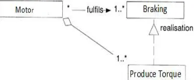
4.2.4 Relationships between roles
The ISO [28] General Relationship model may be useful here. The following, therefore, represents one possible interpretation of this concept. There are at least two different ways in which roles can be related. Firstly, roles can be related because they interact. In a braking system community, for example, the role of controller &processor and the role of encoder are related because they share the angle value. These relationships can usually be left implicit. However, there are other relationships between roles that should be made explicit for modelling purposes. For example, when a brake fix an angle, a conceptual relationship a braking. is established between that brake and the Motor.
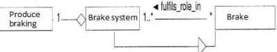
4.2.5 Instantiation
The Communities are created by instantiating the corresponding contract template. Instantiation of a contract involves the assignment of enterprise objects to roles. In general, an object may fulfil many roles, in any number of communities. For example, Controller & Processor may fulfil a controller & Processor role in a system of suspensionan community and also fulfil a
[image:4.612.93.295.296.383.2]determine angle role for the braking community . The fulfils association between enterprise objects and roles Fig.6 is further refined to the enterprise object containing a bit of behaviour, for each role that it fulfils, that realises or implements the role. We call this bit of behaviour the role realiser.
Figure 6: Role Realization
4.2.6 Enterprise behavior
Actions are associated with roles note that actions can, in fact, be associated with more than one object. Roles are used to identify the behaviour of enterprise objects in the community. Behaviour is defined to be ‘‘a collection of actions with a set of constraints on when they may occur,’’ a role definition should also specify these constraints. In a specification language like Mechatronic, for example, constraints on behaviour are specified in terms of a temporal ordering, logical, through invariants on a state space. Fig. 7 depicts one possible interpretation of the clauses pertaining to role behaviour.
Figure 7: Braking Role Behavior
4.2.7 Enterprise policies
[image:4.612.316.519.463.535.2]ISSN: 1992-8645 www.jatit.org E-ISSN: 1817-3195
To ensure that this objective is achieved, a brake policy is established which documents the permissions, obligations and prohibitions for different roles in the braking community. Below we list some real fragments regulations:
- The braking function can be activated anywhere and anytime
-when the brake is activated implicitly angle is fixed
-Encoder sent the value of the angle to the processor, at a very short time species
Figure 8: Policy braking structure
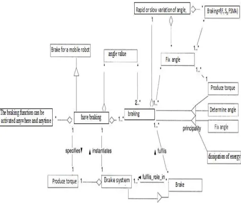
4.2.8 Summary
[image:5.612.305.527.107.334.2]Fig. 9 depicts a summary of the ODP enterprise viewpoint language given as a meta-model. We used the meta-modelling approach to define mapping between ODP Enterprise specification and Mechatronics Enterprise specification. One way to do this mapping is to find both the functional structure and the implementation structure and then relate the bounded artifacts to each other. Table 1 shows an overview of the mapping from ODP Enterprise specification to Mechatronics Enterprise specification.
Figure:9 A Meta-Model For The Mechatronic Enterprise Specification
Table 1 : ODP Enterprise specification to Mechatronic (brake system) Enterprise specification
ODP Enterprise Language Mechatronic Enterprise language
community Brake system
Community template Brake for a mobile robot
objective Produce braking
Enterprise object Brake, processor, encoder Actor Role Produce torque
Artefact role Determine angle Principal Role Fix angle
Enterprise policy The braking function can be
activated anywhere and anytime
Enterprise behaviour Rapid or slow variation of angle, friction, power Enterprise role braking
Enterprise contract Angle value
Behaviour constraint Braking=f(Fr, Sp , FSMA)
5. USING THE UML TO SPECIFY THE
ENTERPRISE VIEWPOINT
The mechatronic enterprise viewpoint is defined as '' a viewpoint on an mechatronic system and its environment that focuses on the purpose, scope and policies for this system. «The enterprise viewpoint langage offers the basic concepts that are needed to represent an mechatronic system in the context of the enterprise in which it operates. In this section, we investigate how the UML [29] can be used to provide a concrete syntax for parts of. The mechatronic enterprise viewpoint language. The use of UML is illustrated by means of a the brake system enterprise specification.
5.1 Brake system community
[image:5.612.66.304.490.691.2]ISSN: 1992-8645 www.jatit.org E-ISSN: 1817-3195
Figure10: The Brake System Community And Its Objective.
5.2 Modeling roles and their relationships
The roles of the brake system community is to have braking anytime and anymore, their relationship, the controller & processor class , also depicted in Fig. 11, is an example of a conceptual relationship between the brake and motor roles.
Figure11: The Brake System Community Structure
5.3 Summary of mappings
Table 2 summarises how the UML can be used as a concrete notation for the mechatronic
enterprise viewpoint. It describes the mapping from the mechatronic enterprise language concepts to UML constructs.
TABLE 2: Mapping Between Mechatronic Enterprise Language And UML Construct
Mechatronic enterprise languageUML CONSTRUCT
Community: Brake system Package
Enterprise object: Brake, processor, motor, power
class
Enterprise role : fix angle, class
Produce torque
Role relationship : angle value
Class
Action : convert electrical energy to magnetic energy
Use case
6. CONCLUSION
We proposed the open distributed process model reference of the ISO (International Organization for Standardization) as the meta standard to be recommended to the designers of mechatronics system . The global vision of a system is clarified
by transformation mechanisms of from different
viewpoints.The interest of this framework is to
propose concepts to the designer community eager
to share the practices. This vocabulary makes it possible to clarify the invariants and the general,
structural and functional principles of an
mechatronics system. The work presented in this paper aims to define various instances of such a meta standard and thus to illustrate the various contributions from this model for the mechatronics community. We have used the UML to build up a meta-model for the ODP enterprise viewpoint lan-guage. We found that the UML is a useful instrument for such an exercise. It allowed us to depict the relationships between the various concepts defined in the enterprise viewpoint language in a clear, concise and consistent manner. Moreover, the conceptual diagrams are easily communicated between multiple stakeholders which have different view-points and therefore use different concepts, models and tools to deal with their concerns of interest. Future work, we will investigate the support for the specification of Quality of Service (QoS) in Event-B when modelling mechatronic System in the enterprise viewpoint.
REFRENCES:
[1] Comerford, R. (1994). Mecha...what ? IEEE Spectrum, pages 46–49.
[2] Grimheden, M. et Hanson, M. (2001). What is
mechatro-nics ? proposing a didactical
approach to mechatronics. In 1st Baltic Sea
Workshop on Education in Mechatronics, Kiel, Germany
[2] Grimheden, M. et Hanson, M. (2001). What is
mechatro-nics ? proposing a didactical
approach to mechatronics. In 1st Baltic Sea
ISSN: 1992-8645 www.jatit.org E-ISSN: 1817-3195
[3] Khalfaoui, S. (2003). Méthode de recherche
des scénarios redoutés pour l’évaluation de la sûreté de fonctionnement des systèmes
mécatroniques du monde au-tomobile. PhD
thesis, Institut National Polytechnique de Toulouse
[4] Thesame (2003). La mécatronique à l’épreuve
du marché. Jitec.
[5] Saviuc, V. (2006). La mécatronique
intelligente. Jitec.
[6] Rzevski, G. (2003). On conceptual design of
intelligent mechatronic sys-tems.
Mechatronics, 13(10) :1029–1044.
[7] Grimheden, M. et Hanson, M. (2001). What is mechatro-nics ? proposing a didactical approach to mechatronics. In 1st Baltic Sea Workshop on Education in Mechatronics, Kiel, Germany.
[8] Hewit, J. (1996). Mechatronics design - the key
to performance enhance-ment. Robotics and
Autonomous Systems, 19 :135–142.
[9] Isermann, R. (2007). Mechatronic systems -
innovative products with embedded control.
Control Engineering Practice, 10 :16.
[10] Millbank, J. (1993). Mecha-what !
Mechatronics Forum Newsletter, 6.
[11] Kortum, W., Goodall, R. M., et Hedrick, J. K.
(1998). Mechatronics in ground
transportation-current trends and future
possibilities. Annual Reviews in Control, 22
:133–144.
[12] Ollero, A., Boverie, S., Goodall, R., Sasiadek, J., Erbe, H., et Zuehlke, D. (2006).
Mechatronics, robotics and components for automation and control : Ifac milestone
report. Annual Reviews in Control, 30(1) :41–
54.
[13] Martin Törngren, Ahsan Qamar, Matthias Biehl, Frederic Loiret, Jad El-khoury-
Integrating viewpoints in the development of
mechatronic products- Mechatronics Volume
24, Issue 7, October 2014, Pages 745–762
[14] Rieuneau, F. (1993). Sûreté de fonctionnement
en phase de develop-pement des systèmes
embarqués automobiles. In Integrated
Logistics & Concurrent Engineering,
Montpellier.
[15] DesJardin, L. (1996). A day in the life of
mechatronic engineers 10 years from now. In
SAE International Congress and Exposition, number SAE96C038, Detroit/Michigan, USA. [16] Borner, M., Straky, H., Weispfenning, T., et
Isermann, R. (2002). Model based fault
detection of vehicle suspension and hydraulic
brake systems. Mechatronics, 12(8) :999–1010.
[17] Demmou, H., Khalfaoui, S., Guilhem, E., et
Valette, R. (2004). Critical scenarios derivation
methodology for mechatronic systems.
Reliability Engineering & System Safety, 84(1) :33–44
[18] Schoenig, R. (2004). Définition d’une
méthodologie de conception des systèmes
mécatroniques sûrs de fonctionnement. PhD
thesis, Institut National Poly-technique de Lorraine
[19] Siemers, C., Falsett, R., Seyer, R., et Ecker, K.
(2005). Reliable event-triggered systems for
mechatronic applications. Journal of Systems
and Software, 77(1) :17–26.
[20] ISOrIEC, Open Distributed Processing —
Reference Model — Part 2: Foundations.
International Standard 10746-2, ITU-T
Recommendation X.902, January 1995.
[21]. A.Balouki, Y.balouki the specification of
quality of service in open distributed
processing: formalism used in mechatronic
system Jatit 15 September 2012. Vol. 43 No.1
[22] A. Johar and R. Stetter INTERNATIONAL
DESIGN CONFERENCE - DESIGN 2008
Dubrovnik –( Croatia, May 19 - 22, 2008. [23 ]https://en.wikipedia.org/wiki/RM-ODP
[24] ISO/IEC, ‘’Basic Reference Model of
Open Distributed Processing-Part1:
Overview and Guide to Use, ‘’ISO/IEC CD 10746-1, 1994
[25] ODP enterprise viewpoint specification
M.W.A. Steen, J. Derrick) Computing
Laboratory, UniÍersity of Kent at Canterbury,
Canterbury CT2 7NF,UK Accepted 13 January 2000
[26] ISOrIEC, Open Distributed Processing —
Reference Model — Part 2: Foundations.
International Standard 10746-2, ITU-T
Recommendation X.902, January 1995.
[27] ISOrIEC. Open Distributed Processing —
Reference Model— Enterprise Viewpoint.
Working Draft 15414, ITU-T
Rec-ommendation X.911, January 1999.
[28] ISOrIEC. Open Distributed Processing —
Reference Model— Enterprise Viewpoint.
Working Draft 15414, ITU-T
Rec-ommendation X.911, January 1999.
[29] S. Kent, S. Gaito, N. Ross, A meta-model
semantics for structural constraints in UML, in: H. Kilov, B. Rumpe, I. Simmonds Eds. ., Behavioral Specifications for Businesses and
Systems, Kluwer Academic Publishers,