ISSN: 1992-8645 www.jatit.org E-ISSN: 1817-3195
AN INTEGRATED TECHNIQUE TO MAXIMIZE THE
EFFICIENCY AND POWER FACTOR OF INDUCTION
MOTOR
1N.ANBALAGAN AND 2S. CHENTHUR PANDIAN
1
Assistant Engineer, TANGEDCO, Erode
2Principal, Dr.Mahalingam College of Engineering and Technology 1E-mail: [email protected]
ABSTRACT
In this paper, an integrated technique to maximize the efficiency and power factor of induction motor is proposed. In the proposed method Artificial Bee Colony (ABC) algorithm is used to optimize the induction motor’s parameters like efficiency and power factor at particular loading points. From the optimized parameters the exact values can be predicted by using the Fuzzy Logic Controller (FLC) during the intermediate loading conditions, because the ABC parameters are not providing the exact parameters for all type of loading conditions. The proposed work is implemented using MATLAB/Simulink platform and performance of the proposed technique is evaluated. Finally, the power factor and efficiency of proposed technique is evaluated with ABC and FLC.
Keywords: ABC, FLC, Induction Motor, Efficiency, Power Factor.
1. INTRODUCTION
In industry [1], the three-phase induction motors are the most widely used electric motors. They run at basically constant speed from no-load to full-load. On the other hand, the speed is happening dependent and accordingly these motors are not simply adjusted to speed control [2]. When huge speed deviations are needed, we generally choose D.C. motors. To go with most industrial necessities, nevertheless, the 3-phase induction motors are plain, rugged, low-priced, easy to sustain and can be factory-made with physiognomies. We shall spotlight our awareness on the common principles of 3-phase induction motors [3]. For drives needed variable speeds due to relieve of their speed control methods [4], only DC motors were used before. The conservative methods of speed control of an induction motor were either too costly or too incompetent thus limiting their application to only steady speed drives [5]. Conversely, modern developments and growth of speed control methods of an induction motor have improved the use of induction motors in electrical drives widely.
The starting device needs more space and moreover adds to the price of the motor. A 1-phase motor is about 30% larger than an equivalent 3-phase motor [6] for the similar output. The features
of single phase induction motors are the same to 3-phase induction motors apart from that single 3-phase induction motor has no intrinsic starting torque and some particular provision have to be ready for making itself starting [7]. It follows that during starting period the single phase induction motor should be changed to a kind which is not a single phase induction motor in the logic in which the phrase is normally used and it turns into a correct single phase induction motor when it is sprinting and following the speed and torque have been increased to a point outside which the additional device may be distributed [8].
In this paper, an integrated technique to maximize the efficiency and power factor of induction motor is proposed. In the proposed method Artificial Bee Colony (ABC) algorithm is used to optimize the induction motor’s parameters like efficiency and power factor at particular loading points. The exact parameters can be predicted by using the FLC while the parameter variation at various loading conditions. Because the ABC parameters are not adapted for all type of loading conditions. The rest of the paper organized as follows: the recent research works is analyzed in section 2; the proposed work brief explanation is explained in section 3; the suggested technique achievement results and the related discussions are
given in section 4; and section 5 ends the paper.
2. RECENT RESEARCH WORKS: A BRIEF REVIEW
In literature, several associated works are previously accessible which stands to progress the competence and power factor of induction motor. A few of them assessed here. Three phase induction motors are used in more or less all the industries for its easy construction and easy function has been proposed by V.Chandrasekaran et al. [17]. More than 60% of the electrical energy produced was being devoured by the induction motors was expected. Any effort to develop the competence and power factor will cost efficient. For the induction motor which proficient operation with power factor development is feasible by substituting a Double Winding Induction Motor (DWIM). Due to mutual induction that labors as an Induction Alternator (IA), a three phase EMF was extended in the other winding. For its highest competence and power balancing modes of operation both mechanical and electrical load can be controlled by a PIC Microcontroller. The development in competence and power factor is proved by a capacitor bank with inconsistent steps comprised in the designed model. Besides, energy conservation was feasible owing to loading the second set of winding for which divide supply is not needed.
Linear electrical motors (LMs) linear motion has been proposed by A. Hassanpour Isfahani et al. [18. They undergo from two major disadvantages: low competence and low power factor. Elevated energy consumption and an increase in input current, and occupy transmission line capacity are caused by these disadvantages. Concurrently, to progress both competence and power factor, they offer a multi-objective optimization technique. To work out the competence and power factor, these techniques use
a systematic model of the machine. It permits us to examine the effects of different motor conditions on the competence and the power factor. By applying a genetic algorithm in a suitable objective function, Motor parameters and dimensions can be optimized after that. The results demonstrate an improvement in motor concert.
The low-load operating periods, motor concert in terms of competence and power factor has been proposed by Fernando J. T. E. Ferreira et al. [19]. In this offered method, as a function of load, a multiflux level, three-phase, squirrel-cage induction motor was offered, in which the competence and power factor can be both exploited. This new motor can be an extra value in industry owing to its flexibility, mainly, for changeable load applications in which major energy savings can be attained, and can furthermore be applied as novel or re-wound common purpose spare motor. The suggested motor has a stator winding with two sets of turns, allocating the similar positions in the stator slots. Six modes were chosen and examined among all the feasible stator winding connections. The fundamental principles for suitable connection mode change were argued. An electronic device and a contactor thought for automatic connection mode change were suggested.
The power of the derange factors in calculating total copper losses, competence, power factor, input power, output torque, peak currents, and derating factor of the motor operating under unstable voltage system has been assessed by Makbul Anwari et al.
[20]. The entire definition for the voltage unhinge is using complex voltage-unbalance factor that contains its magnitude and angle. A coefficient to decide either under- or over unhinge conditions was introduced. Using the method of symmetrical component, the study of the motor was executed, and MATLAB software was applied to examine the concert of the induction motor. To assess total copper losses, input power, power factor, and total output torque exactly, the reproduction results demonstrate that the International Electro technical Commission definition of the voltage unhinge combined with the coefficient of unbalance condition could be used. Conversely, the phase angle of the unbalance factor should be embraced for correct calculation of peak current and peak copper losses of the phase windings and derating aspect of the motor.
Linear induction motors (LIMs) linear motion directly has been proposed by Amir Zare Bazghaleh
ISSN: 1992-8645 www.jatit.org E-ISSN: 1817-3195
foremost problems. At first, they offer an exact equivalent circuit model (ECM) in this suggested method. After that, they insert a factor, which can show the end effect intensity in the LIM. We examine the influence of motor design parameters on the competence, power factor, and end effect intensity at the subsequent stage. We grow a number of different multi-objective functions, which will be applied to develop competence, power factor, end effect intensity, and motor weight afterward. Results will demonstrate the precision of the equivalent circuit model and the enhancement of objective functions at the last part of the optimization process. Two-dimensional finite-element study assesses the results from the ECM.
Regarding the competence developments to electrical machines that could have an extremely large bang on energy consumption has been discussed by B.C.Mecrow et al. [22]. The key disputes to improved competence in systems forced by electrical machines stretch out in three areas: to lengthen the application of variable-speed electric drives into novel areas by reduction of power electronic and control costs; to incorporate the drive and the driven load to exploit system competence; and to raise the competence of the electrical drive itself. Competence gains inside electrical machines would result from the growth of new materials and construction techniques is done in the little to medium term. Roughly a quarter of novel electrical machines were driven by variable-speed drives. More than the subsequent 50 years, these were a less mature product than electrical machines and must see bigger competence gains. With novel sorts of power electronic devices that diminish switching and conduction loss, progress would happen. There was an entire freedom to differ the speed of the driven load with variable-speed drives. Substituting fixed-speed machines with variable-speed drives for an elevated ratio of industrial loads could signify 15–30% energy save. This could set aside the UK 15 billion kWh of electricity per year which, when joined with motor and drive competence gains, would amount to a total annual saving of 24 billion kWh.
A technique based on multi-objective evolutionary algorithms for the purpose of in-service induction motor efficiency has been presented by Mehmet cunkas et al. [22]. In common, the competence was found out by collecting multiple objectives into one objective by a linear amalgamation and optimizing the resulting single-objective problem. The approach has a few disadvantages such that precise data about solution
substitutes would not be willingly evident. They explained the multi-objective evolutionary optimization algorithms, the Non-dominated Sorting Genetic Algorithm-II (NSGA-II) and Strength Pareto Evolutionary Algorithm-2 (SPEA2), were effectively used to the competence purpose problem in induction motor.
The improvement of induction motor efficiency and power factor are significant not only from the concerns of energy savings and cooler system operation, but also from environmental pollution avoidance possible. The vantage points of energy savings and related air pollution abatement, it is clear that higher induction motor operating efficiency is an issue. The efficiency of an induction motor system is a complex function of the motor, converter, and control system. So that in literature, different types of control technique is used for improving the efficiency and power factor of induction motor. The conventional control of an induction motor is complicated due to strong nonlinear magnetic saturation effects and temperature dependence of the motors electrical parameters. In general, the conventional control approaches need a compound mathematical model of the motor to expand controllers for measures such as speed, torque, and position. This mathematical model based calculations have to be achieved particularly for each motor, and the resulting model based controllers may not execute well if temperature change causes parameter values to change. So that, the inconvenience of the online search approaches includes their complexity as well as their potential propensity to exhibit slow convergence.
3. PROBLEM FORMULATION
well if temperature change causes parameter values to change. So the inconvenience of the online search approaches includes their complexity as well as their potential propensity to exhibit slow convergence. The efficiency and the power factor improvement are explained in the next section 3.1.
3.1. Maximization of Efficiency and Power Factor of Induction Motor
The efficiency and the power factor of the induction motor are maximized by the optimization and prediction of the induction motor parameters. Here we are using the Artificial Bee Colony algorithm (ABC) for optimizing the parameters. From the optimized parameters, the exact value can be predicted by the Fuzzy Logic Controller (FLC) technique during the parameters variation time. It predicts the exact parameters using the expert knowledge rules base interference system. So, the proposed technique gives maximized efficiency and power factor at different mechanical torque levels. The proposed induction motor equivalent circuit and the mathematical modeling are given in the following section 3.1.1.
3.1.1. Equivalent Circuit and Mathematical Modeling of the Induction Motor
The proposed induction motor equivalent circuit is shown in figure 1, which shows the stray load losses. In this circuit, Vs is the stator phase voltage,
R
s andR
r are the stator and rotor resistance respectively, Xs and Xrare the stator and rotor leakage reactance respectively, Rsy is the stray load resistor, Rmand Xm are the magnetizing resistance and leakage reactancerespectively,
I
sandI
r are the stator and rotorcurrent, Rr[(1−S) S]represents the output power of the motor. The stray resistor
R
syis representing the stray losses of the circuit. The stray losses can be determined by the following equation (1).Figure.1. Equivalent Circuit Of The Induction Motor
= ) ( 2 2 FLD r r FLD sy sy I I P
P (1)
Where, Psyand PsyFLD are the stray load losses at any point and full load,
I
randFLD r
I are the rotor current at any load point and full load. Here the stray resistance can be calculated by the following equation (2).
− = 100 8 . 1 ] ) 1 (
[ FLD FLD
r
sy R S S
R (2)
Where,
S
FLDis the full load slip, let us consider the stray losses can be evaluated at full load 1.8%. The four equivalent circuit parameters)
,
,
,
(
X
sR
rX
mR
m are to be estimated. The efficiency and power factor of the equivalent circuit has been estimated in the following,(a) Estimation of Efficiency and Power Factor
The efficiency of the three phase induction motor can be estimated by the following equation
100 (%) = E inp E out E P P
η (3)
Where, ηE(%) is the estimated efficiency in
percentage,
P
outE andP
inpE are the estimated output and input power. Here, the output power and input power of the induction motor can be estimated by the following equations (4) and (5). − = S S R I
PoutE (3 r2E r) 1 (4)
] )
( [
3 s2E s r2E r sy m2E m
E
inp I R I R S R I R
P = + + + (5)
Where, m r s r s E s E s Y Y Y Y Y V I + +
= is the estimated stator
current, m r s r E s E r Y Y Y Y V I + +
= is the estimated rotor
current,
) ( s r m m r E s E m Y Y Y R Y V I + +
= is the estimated
magnetizing current.
With, V Vs
(
3 j0)
E
s = + is the stator per phase
ISSN: 1992-8645 www.jatit.org E-ISSN: 1817-3195
s s s
jX R Y
+
= 1 is the stator admittance,
s sy r r
jX R S R Y
+ + =
) (
1 is the rotor admittance,
m m m
R X
Y =− 1 + 1 is the equivalent admittance
of the parallel branch.
The three phase induction motor power factor can be calculated by the following equation (6).
E s
E s E
I I al
Cosφ =Re ( ) (6)
The above parameter estimations are used to identify the induction motor operation efficiency and power factor at various loading points. It should be estimated from half loading to over loading conditions. The actual efficiency and power factor of the induction motor at various loading points are determined by the different techniques. It is important to note that these measured parameters are used to compare and verify the estimated efficiencies. Then the determined parameters are compared with the estimated efficiency and power factor. Minimization of error between them is considered as the fitness function of the proposed method. This integrated proposed algorithm needed multi-objective function for the reduction of error. The minimized error between the measured and estimated parameters provides the increased efficiency and the power factor. The integrated proposed system is given in the following section 3.2.
3.2. Overview of the Proposed Integrated Technique
The proposed technique contains the combined performance of both ABC and FLC algorithms, which are used to maximize the parameters of the induction motor, i.e., the efficiency and power factor. Here we are using the ABC for optimizing the parameters of the induction motor. From the optimized parameters, the exact value can be predicted by the FLC technique during the parameters variation time. It predicts the exact parameters using the expert knowledge interference system. The ABC algorithm for optimizing the parameters is briefly explained in the following section 3.2.1.
3.2.1. Optimizing the Parameters Using ABC Algorithm
The ABC algorithm optimizes the parameters, i.e., to minimize the error between the actual and
estimated parameters. Initially the population size, iteration range and total number of generation should be clearly specified using the induction
motor parameters i.e.,
X
s,
R
r,
X
m,
R
m,
X
r to determine the efficiency and power factor at the various loading points. It should be compared with the experimental measurements and the error between them is reduced using the multi-objective functions. The steps to optimize the induction motor efficiency and power factor is briefly explained in the following,Algorithm
Step 1: Initialize the population solution
(
X
i)
of the induction motor equivalent circuit parameters i.e.,Xs,Rr,Xm,Rm,Xr.Step 2: Generate the random number of population of input current, efficiency and power factor.
Step 3: Evaluate the fitness of the population; the multi-objective function is given in the following equation (7).
{
f1(x),f2(x),f3(x)}
Min
F x∈
=
Φ (7)
The absolute error function of the multi-objective formulation can be described in the following manner
.
A s E
s I
I x
f1( )= − (8)
A inp E
inp P
P x
f2( )= − (9)
A E
COS COS
x
f3( )= φ − φ (10)
Step 4: Set the cycle count is 1, i.e., cycle=1.
Step 5: Repeat
Step 6: To adjust the populations and determine the new solutions of the employee bee using the following equation (11).
)
( , ,
, ,
,j i j i j i j k j
i x x x
V = +Φ − (11)
Where, k=(1,2,3n)and j=(1,2,3n) are the randomly chosen index.
Step 7: Apply the selection process to find the better fitness of the new solutions and determine the probability.
∑
=
Φ Φ =
n
i
y probabilit
1
(12)
solution selected is depending on the probability and evaluate it.
Step 9: Apply selection process of the new solutions.
Step 10: If better solutions are not achieved, abandon the solutions and produce the random number of scout bee solution using the following equation (13).
) ](
1 , 0
[ max min
min
j j j
j
i x rand x x
x = + − (13)
Step 10: Store the best solution achieved so far.
Step 11: Cycle=cycle+1
Step 12: until cycle= maximum cycle number.
Once the process has been completed, the algorithm is ready to give the efficiency and the power factor of the induction motor. These results are used to identify particular load points, for which the range is half load to over load conditions, i.e., 50, 75, 100, 125 (in %). But for the intermediate load conditions, the maximized efficiency and power factor calculations are difficult process in the ABC. So integrating the process using the FLC, is given in the following section 3.2.2.
3.2.2. FLC Based Exact Parameters Prediction
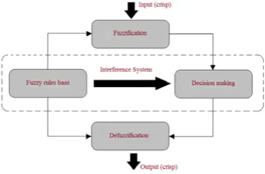
[image:6.612.102.290.534.657.2]The FLC is the universal approximation logic rules based technique, which has the merits such as independence of mathematical model, robustness, and linguistic description. Here, FLC is used to predict the exact parameters of the induction motor during various load conditions. Normally FLC consists of three stages such as fuzzification, interference system and defuzzification. The proposed FLC structure is given in the following figure 2.
Figure.2. Structure of the proposed FLC
(i) Fuzzification
The input crisp values are converted into the fuzzy values, during the fuzzification process. At that
process the boundaries of the crisp values should be specified. Here the induction motor load and input power is the input of the FLC. The input may be the following
{
(50%), (51%), ( %)}
)
(x P P P n
Pinp = inp inp inp (14) Where, PinpF (x) is the input power at
x
percentage of load.(ii) Interference System
This is the expert knowledge rules base system, which contains the fuzzy rules base and decision making system. The various loading conditions corresponding efficiency and power factor are created by some meaningful rules, which is given in the following
If the fuzzified input power is
{
(50%), (51%), ( %)}
)(x P P P n
PinpF = inpF inpF inpF (15) Then the efficiency and the power factor is given by,
{
(50%), (51%) ( %)}
)
(x AF AF AF n
AF η η η
η =
and
=
%) ( %)
51 (
%), 50 ( )
(
n COS COS
COS x COS
AF AF
AF AF
φ φ
φ φ
(16)
Where, ηAF(x) is the efficiency at
x
percentageof load and COSφAF(x) is the efficiency at
x
percentage of load (all are fuzzy values).(iii) Defuzzification
The predicted parameters are in the form of fuzzy values, which are converted into the crisp values using the defuzzification process.
{
(50%), (51%) ( %)}
)
(x DF DF DF n
DF η η η
η =
and
=
%) ( %)
51 (
%), 50 ( )
(
n COS COS
COS x COS
DF DF
DF DF
φ φ
φ φ
(17)
Where,
η
DF(
x
)
is the efficiency at
x
ISSN: 1992-8645 www.jatit.org E-ISSN: 1817-3195
4. EXPERIMENTAL RESULTS AND DISCUSSIONS
The proposed method has been implemented in the MATLAB (2012a) platform. Here, the proposed method reduces the error between the estimated induction motor parameters and the actual parameters under various load conditions. The load should be varying between half to overloading condition. This evaluation provides the best efficiency and power factor of the certain load conditions. In this proposed method using the 5.4 HP, 380V, 50Hz, 4 pole induction motor, the parameters configurations can be described in the following table 1.
Table.1: Induction Motor Parameters
Parameters Values in ohm
Stator resistance (Rs) 3.9
Rotor resistance (Rr) 4.2
Stator reactance (Xs) 6.6
Rotor reactance (Xr) 6.4
Mutual resistance (Rm) 136.5
Mutual reactance (Xm) 1382
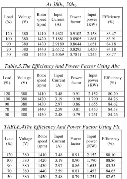
[image:7.612.307.525.80.734.2]The three phase induction motor estimated power factor and efficiency under various loading condition can be described in the table 2. The parameters estimation can be done with the help of equations (3) and (4). The estimated induction motor parameters are compared with the various techniques parameters such that ABC, FLC and proposed technique. The table 3 shows the three phase induction motor parameters, which has been determined by the ABC algorithm. Similarly the FLC using calculated parameter are given in the table 4. The optimized induction motor parameters using the proposed method are described in the table 5. Here, the proposed method optimized the induction motors parameters using the ABC algorithm, i.e., to minimize the objective function. From the optimized parameters, the exact value can be predicted by the FLC technique during the parameters variation time. Then the effectiveness of the proposed method effectiveness has been analyzed in the tables 6 and 7 (all values are given in percentage). In the tables below error between the estimated parameters and the actual parameters (determined from various techniques) are evaluated.
Table.2. Estimated Data Of Three Phase Induction Motor At 380v, 50hz.
Load (%)
Voltage (V)
Rotor speed (rpm)
Input Current
(A) Power factor
Input power (KW)
Efficiency (%)
120 380 1410 3.4621 0.9102 2.158 83.47 100 380 1420 3.1881 0.8905 1.861 83.91 90 380 1430 2.9189 0.8644 1.651 84.18 70 380 1440 2.6572 0.8293 1.450 84.18 50 380 1450 2.4069 0.7811 1.245 83.77
Table.3.The Efficiency And Power Factor Using Abc
Load (%)
Voltage (V)
Rotor speed (rpm)
Input Current
(A) Power factor
Input power (KW)
Efficiency (%)
120 380 1410 3.48 0.91 2.152 80.20 100 380 1420 3.19 0.90 1.790 84.26 90 380 1430 2.97 0.86 1.655 84.62 70 380 1440 2.59 0.81 1.453 84.58 50 380 1450 2.48 0.79 1.251 84.26
TABLE.4The Efficiency And Power Factor Using Flc
Load (%)
Voltage (V)
Rotor speed (rpm)
Input Current
(A) Power factor
Input power (KW)
Efficiency (%)
[image:7.612.315.525.102.396.2]120 380 1410 3.48 0.91 2.152 80.10 100 380 1420 3.19 0.90 1.790 88.86 90 380 1430 2.97 0.86 1.655 85.35 70 380 1440 2.59 0.81 1.453 84.65 50 380 1450 2.48 0.79 1.251 82.62
Table.5The Efficiency And Power Factor Using Proposed Method
Load (%)
Voltage (V)
Rotor speed (rpm)
Input Current
(A)
Power factor
Input power (KW)
Efficiency (%)
120 380 1410 3.48 0.9751 2.152 84.02 100 380 1420 3.19 0.9509 1.790 84.04 90 380 1430 2.97 0.8499 1.655 85.00 70 380 1440 2.59 0.8624 1.453 83.90 50 380 1450 2.48 0.7485 1.251 84.01
Table.6Comparison Of Efficiency Errors In Percentage
Load
(%) ABC FLC
Proposed technique
120 3.27 3.37 0.55
100 0.35 4.95 0.13
90 0.44 1.17 0.82
70 0.4 0.47 0.28
50 0.49 1.15 0.24
Table.7 Comparison Of Power Factor Errors In Percentage
Load
(%) ABC FLC
Proposed technique
120 0.0668 0.0668 0.0649
100 0.0665 0.0665 0.0604
90 0.0344 0.0344 0.0145
70 0.0417 0.0417 0.0331
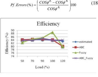
[image:7.612.314.522.393.713.2]The estimated percentage efficiencies and percentage efficiencies for ABC, FLC and the proposed are illustrated in the figure 3, which is determined according to the load variations. The errors between the estimated efficiency and actual efficiency (determined from various techniques) are shown in the figure 4. The estimated power factor and power factor for various techniques in different loading points are described in the figure 5. The errors between estimated power factor and the various techniques power factor are illustrated in figure 6 (all in percentage). The power factor errors percentage can be calculated using the following equation.
100 (%)
.
−
=
A A E
COS COS COS Errors
Pf
φ φ
[image:8.612.318.522.82.211.2]φ (18)
[image:8.612.95.294.256.716.2]Figure.3.The Percentage Efficiencies For Various Techniques
Figure.4. Comparison Of Efficiency Errors In Percentage
[image:8.612.96.296.265.422.2]Figure.5.The Power Factor For Various Techniques
Figure.6. Comparison Of Power Factor Errors In Percentage
The three phase induction motor parameters are estimated with the appropriate equations and specified values. This can be determined for various loading conditions i.e., half loading to over loading conditions. The various techniques are used to determine the actual parameters of the induction motor such as ABC, FLC and proposed technique; it is also determined for half loading to over loading conditions. Then the effectiveness of the proposed technique has been described in the graphical representation. Comparing to the other techniques parameters, proposed technique parameters are much closer to the estimated parameters. Also it can be proved by the additional computation analysis process. In the analysis used to calculate the percentage error in efficiencies and the percentage error in power factor, which describes the proposed method has the minimized errors compared to the other techniques. For example percentage errors in efficiency for half loading condition are given in the following, ABC has
0.49%, FLC has 1.15% and the proposed technique has 0.24%. Similarly for the percentage errors in power factor for 70% loading condition are given in the following, , ABC has 0.0344%, FLC has
0.0344% and the proposed technique has 0.0145%.
5. CONCLUSION
[image:8.612.98.293.454.583.2] [image:8.612.97.289.603.711.2]ISSN: 1992-8645 www.jatit.org E-ISSN: 1817-3195
nominal loads. The proposed method performance is compared with the ABC and FLC. The comparative results have proved that the proposed technique is the well improved technique to maximize the efficiency and power factor of the induction motor compared to the other techniques.
REFERENCES
[1] Soltani W., Szabados, B. and Hoolboom, G., “A new synthetic loading for large induction machines with no feedback into the power system”, IEEE Transactions on Energy Conversion, Vol.17, No.3, pp.19-324, 2002. [2] Otten G, de Vries, T.J.A., van Amerongen, J.,
Rankers, A.M. and Gaal, E.W., “Linear motor motion control using a learning feedforward controller”, IEEE/ASME Transactions on Mechatronics, Vol.2, No.3, pp.179-187, 1997. [3] Rohini Bhalerao, and Sandeep Hanwate, “Study
of Designing Regulator Systems By Using The Different Observer Approach”, IOSR Journal of Electrical and Electronics Engineering, Vol. 1, No. 5, pp. 1-5, 2012.
[4] Bose, B.K. “Technology trends in microcomputer control of electrical machine”,
IEEE Transactions on Industrial Electronics,
Vol. 35, No. 1, pp. 160-177, 1998.
[5] P. W. Carlin, A. S. Laxson, E. B. Muljadi, “The History and State of the Art of Variable-Speed Wind Turbine Technology”, Wind Energy, Vol. 6, No. 2, pp. 129–159, April/June 2003.
[6] G.K. Singh, “A research survey of induction motor operation with non-sinusoidal supply wave forms”, Electric Power Systems Research,
Vol. 75, No. 2–3, pp. 200–213, August 2005. [7] Sunitha Undrajavarapu, M. Srinivasa Rao and.
L. Uday Kiran “Pv Fed Boost Spwm Inverter Driven Single-Phase Induction Motor”,
International Journal of Engineering Research and Applications, Vol. 2, No. 4, pp. 2136-2141, July-August 2012.
[8] Sen P.C., “Electric motor drives and control-past, present, and future”, IEEE Transactions on Industrial Electronics, Vol. 37, No. 6, pp. 562-575, 1990.
[9] Campos-Delgado D.U., Espinoza-Trejo D.R and Palacios, E., “Fault-tolerant control in variable speed drives: a survey”, IET Electric Power Applications, Vol. 2, No. 2, pp. 121 -134, 2008.
[10] Bose B.K., “Power Electronics and Motor Drives Recent Progress and Perspective”, IEEE
Transactions on Industrial Electronics, Vol. 56, No. 2, pp. 581-588, 2009.
[11] Bose, B.K “Power electronics and motion control-technology status and recent trends”,
IEEE Transactions on Industry Applications,
Vol.29, No. 5, pp. 902-909, 1993.
[12] C. R. Hinings, D. J. Hickson, J. M. Pennings and R. E. Schneck “Structural Conditions of Intraorganizational Power”,
Administrative Science Quarterly, Vol. 19, No. 1, pp. 22-44, Mar., 1974.
[13] Mohamed A. Eltawil and Zhengming Zhao, “Grid-connected photovoltaic power systems: Technical and potential problems-A review”,
Renewable and Sustainable Energy Reviews,
Vol. 14, No. 1, pp. 112–129, January 2010.
[14] Anton Gustafsson and Magnus
Gyllenswärd “The power-aware cord: energy awareness through ambient information display”, In proceeding Extended Abstracts on Human Factors in Computing Systems, ACM New York, NY, USA, pp. 1423-1426, 2005. [15] Wesley R. Browne and Ben L. Feringa,
“Making molecular machines work”, Nature Nanotechnology, Vol. 1, pp. 25-35, 2006. [16] Robert U Ayres, Leslie W Ayres and
Benjamin Warr, “Exergy, power and work in the US economy, 1900–1998”, Energy, Vol. 28, No. 3, pp. 219–273, March 2003.
[17] V. Chandrasekaran and T. Manigandan, “Double Winding Induction Motor- an Approach for Improvement of Power Factor and Efficiency”, European Journal of Scientific Research, Vol. 66, No.2, pp. 262-273, 2011. [18] A. Hassanpour Isfahani, B. M. Ebrahimi,
and H. Lesani, “Design Optimization of a Low-Speed Single-Sided Linear Induction Motor for Improved Efficiency and Power Factor”, IEEE Transactions on Magnetics, Vol. 44, No. 2, pp. 266-272, February 2008.
[19] Fernando J. T. E. Ferreira, and Anibal T. de Almeida, “Novel Multiflux Level, Three-Phase, Squirrel-Cage Induction Motor for Efficiency and Power Factor Maximization”, IEEE Transactions on Energy Conversion, Vol.23, No.1, pp.101-109, March 2008.
[21] Amir Zare Bazghaleh, Mohammad Reza Naghashan, and Mohammad Reza Meshkatoddini, “Optimum Design of Single-Sided Linear Induction Motors for Improved Motor Performance”, IEEE Transactions on Magnetics, Vol. 46, No. 11, pp. 3039-3047, November 2010.
[22] B.C.Mecrow and A.G.Jack, "Efficiency trends in electric machines and drives", Energy Policy,
Vol.36, No.12, pp.4336–4341, December 2008. [23] Mehmet cunkas and Tahir Sag, "Efficiency