ISSN: 1992-8645 www.jatit.org E-ISSN: 1817-3195
BLOCK IDENTIFICATION METHODOLOGY:
CASE STUDY ON BUSINESS DOMAIN
MUSTAFA ALMATARY, MARINI ABU BAKAR AND ABDULLAH MOHD ZIN
Center for Software Technology and Management Faculty of Information Science and Technology
Universiti Kebangsaan Malaysia 43600 Bangi, Selangor, Malaysia
E-mail: [email protected], [email protected], [email protected]
ABSTRACT
The Block-Based Software Development (BBSD) is a software development approach that enables end users to develop applications by integrating blocks. In order for block based programming approach to be successful, there is a need for a large number of blocks to be developed in various application domains. The BBSD life cycle divided into two parts: Block development for a specific domain (carried out by project initiators and block developers), and block integration (carried out end by users). Block development consists of two stages: block identification and block creation. This paper describes a methodology that can be used for block identification. Through this methodology blocks that are needed for a given domain can be properly determined and specified, which will help blocks developers to develop the right blocks for the domain. The feasibility of the proposed methodology is shown through a case study.
Keywords: End User Software Development, UML, Block-Based Software Development,
Component-Based Software Development .
1. INTRODUCTION
The Block-Based Software Development
(BBSD) is a software development approach that enables end users to develop applications by integrating blocks (Zin 2011). The term “block” refers to a software component that can be reused,
is highly composable, customizable and
configurable. Blocks can be combined with other blocks to form applications without going through the normal coding process [1, 2]. In the current implementation, a block is packed as a JAR (Java Archive) file. JAR files provide a standard mechanism to compress and package a set of files for distribution to users. In order for block based programming approach to be successful, there is a need for a large number of blocks to be developed in various application domains.
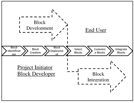
The block-based software development life cycle is shown in figure 1. The development process can be divided into two parts: Block development and block integration. Block development process is carried out by project initiator and block developers, while the block integration is done by End-Users. Within a BBSD, a project initiator is a
person responsible for managing blocks
development for a particular domain. His task is
[image:1.612.312.529.526.692.2]including a new application domain, creating sub-domains and identifying the required blocks for the domain. The process of blocks development will be carried out by professional programmers (in BBSD they are called block developers). Blocks submitted by block developers need to be managed and certified by project initiator, before they can be published and distributed.
Figure 1: Blocks Based Development Life Cycle
The paper proposes the methodology for carrying out the first phase of the block development process that is blocks identification. The availability of this
Block Identificat
ion
Block Creation
Block Deployme
nt
Select Blocks
Customiz e Blocks
Integrate Blocks
Block Development
Block Integration
End User
ISSN: 1992-8645 www.jatit.org E-ISSN: 1817-3195
methodology will help block developers to develop required blocks for a given domain. The suitability of the proposed methodology is validated by using a case study.
2. RELATED WORK
BBSD is a combination of component based software development and end user development [3]. A block is basically a software component. Thus, it is important for us to study related work that has been carried out within component based software development, in particular on the issue related to component identification. End user development is normally carried out by first doing end user requirement analysis. One of the popular tool to do this analysis by using the use case diagram that is provided within the UML notation.
2.1 COMPONENT IDENTIFICATION
Component Identification problem and methods is one of important issues within the software engineering community [4-6]. Most of the component identification methods consists of three steps are: Domain Analysis, CRUD and Clustering [4-11]. Domain analysis is normally done based on conception views of legacy systems expertise; CRUD (Create, Read, Update and Delete) is used to identify the classes and use cases relationship; while Clustering is used to group the similar functionalities and objects that having high relationship.
Surveys by [4-6] shows that several
methodologies for the analysis and design of component identification have been proposed. However, very few of them explicitly focus on EUD (end user development) where the number of end users has been increasing exponentially around the world. The surveys reflected a similar goal of structuring the scope as limited to identifying business components. In addition, the authors did not provide a detailed scheme to heuristically distinguish between approaches with domain-engineering, CRUD matrix, or cohesion-coupling clustering strategies and other methods. Thus, different methodologies serve different needs and there is no methodology serving all requirement processes. So each methodology is good for its designed purposed and task, each approach requiring a proper non-universal, integrated methodology.
Regardless of the component type to be identified, whether it is a business component or a software component, the technique used is forward or backward, and the base of these techniques is domain engineering. Examples of the techniques are Feature-Oriented Domain Analysis (FODA), Feature-Oriented Reuse Method (FORM), Product Line Method (PLM) and Integrating Feature Modeling with the RSEB [12-15], clustering methods (COMO, O2BC, etc.) [16, 17].
2.1 UML
UML became a language of notations modeling techniques in today’s object oriented paradigm [11, 18, 19]. Through UML, the requirement statements given by the stakeholders are presented through the use case diagrams and descriptions.
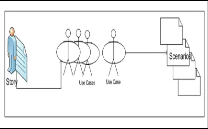
[image:2.612.315.525.547.678.2]The software analysis starts with basic statements gathering from the End Users (stakeholders) by analysts during the system feasibility study. In UML, the user requirements (also known as stories) are nothing but a set of scenarios converted into Use Case [20]. Then, the class diagrams are identified from those use case descriptions while sequence diagrams illustrate the sequence of actions of use case instances (Andrew, 2009). Use cases examine a scenarios in a simple and easy manner by describing a real-world example of how one or more people or organizations interact with a system [21]. Figure 2 illustrates how the End User story can be represented in a number of use cases, where each use case may have a number of scenarios.
Figure 2: The user story, use case and scenarios
ISSN: 1992-8645 www.jatit.org E-ISSN: 1817-3195
[image:3.612.92.293.230.383.2]
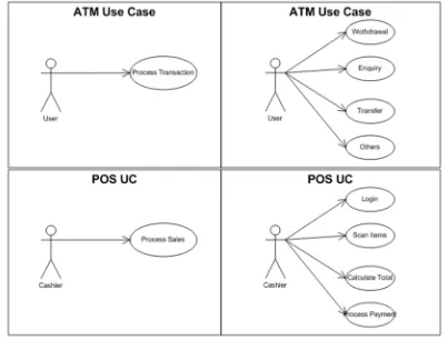
world problems, its flexibility can lead to different levels of use case abstraction (different views of representing a problem). Figure 3 illustrates two possible alternatives for representing ATM and POS. An ATM can be represented simply as a single Process Transaction or as a number of processes (Withdrawal, Inquiry, Transfer, Others). Similarly POS can simply be represented as single Process Sales or as a number of processes (Login, Scan Items, Calculate Total, Do Payment).
Figure 3: ATM and POS Use Case Diagram representation level
3. PROPOSED METHOD
The proposed method for block identification is divided into three stages: domain analysis, sub-domain analysis and block analysis.
Domain Analysis:
The domain analysis consist the following steps and procedure:
Identify main actors: the main actors in the
domain are identified together with the use case interaction between the identified actors.
Create boundaries by identifying actors
interested in: the targeted actors and processes are highlighted and the rest are ignored.
Refine the domain by adding more related
actors and use cases (the targeted use cases are more refined).
Create boundaries of subdomain if any (here
if more than sub domain targeted, the
bounders of each subdomain are
highlighted).
SubDomain Analysis:
The subdomain analysis consist the following steps and procedures:
Select the target subdomain (after use cases
are identified and boundaries are
highlighted, the target subdomain is
selected).
Refine that particular subdomain (here
abstracted uses case are more analysed and the extended and used use cases are identified).
Create class diagram (here the class
diagrams are identified to represent the real world problem in an object oriented manner.
Block Analysis:
Identify scenarios (all the possible scenarios
of each use case are identified, thus, the relationship between actors, use case, with possible alternatives and relationship are identified as shown in table 1).
Create Use Case flow (all the possible
alternatives are identified )
Create Tickets (Create CRUD Matrix,
identify the relationship between use cases and classes as shown in table 2).
Identify Blocks and Refine (based on the
strong relationship identified in CRUD Matrix the blocks are identified and then refinement is done if needed to compose blocks together).
Block Specification (finally, the required
blocks are identified and each block specification is illustrated in standard doc called required Block Specification).
The complete successful (happy) scenarios in use case are identified and then the possible alternatives and relationship between use cases and classes in a target subdomain represented in CRUD matrix. Since CRUD stands for C Create, R Read, U Update, or D Delete, each level is represented by a value 1 – 4 based on the operation (R=1, C=2, U=3, D=4).
4. CASE STUDY
ISSN: 1992-8645 www.jatit.org E-ISSN: 1817-3195
the Business Domain to be studied since the requirement for this domain is clearly specified.
4.1 DOMAIN ANALYSIS
Domain analysis involves five steps as follows:
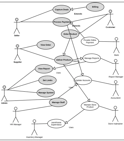
Identify main actors: Through use case
analysis, main actors in business domain and interaction between these actors can be identified, as shown in Figure 5.
Accountent
Customer
Admin
Store maintainer Bank
Inventory Manager HR Manager
Report Manager Update Accounts
Capture Deals
Seller
Set Limits deliver Product Supplier
Order Product
Mantain Store Product
warehouse Supervisour
Manage System
Manage Staff
Manage Reports Provide Online
Payment
Process Payment Extends
Billing
Extends
View Order
Extends
Uses
Uses
View Report
Uses
Figure 5: Main Actors in Business Domain and Boundary
Create a domain boundary: The domain
boundary is determined by identifying required actors and use cases. Figure 5 illustrates that the required actors (Sellers, Customers, Suppliers and Admin) and use cases are highlighted and their use cases.
Accountent
Customer
Admin
Store maintainer Bank
Inventory Manager HR Manager
Report Manager Update Accounts
Capture Deals
Seller
Set Limits deliver Product
Supplier
Order Product
Mantain Store Product
warehouse Supervisour
Manage System
Manage Staff
Manage Reports Provide Online
Payment
Process Payment Extends
Billing
Extends
View Order
Extends
Uses
Uses
View Report Uses Display Sales
information
Extends
Validate Payment Uses
Uses Calculate Totals
& Tax Extends
Delivery Acknowledgment
[image:4.612.91.302.214.454.2]Check Stock
Figure 6: Business Domain Boundary and Use Case Refinement
Refine domain: After main actors and use cases
have been identified, a series of refinement of the intended use cases can be carried out in order to describe processes in more detail and identify all required and extended use case as shown in figure 6 such as capture deals extends the payment validation and billing use cases.
4.2 SUBDOMAIN ANALYSIS
Since the business domain is large, a subdomain analysis can be carried out to identify the subdomain that need to focus in the block development process. Subdomain analysis can be done as follows:
Chosen Subdomain Refinement: In this step
ISSN: 1992-8645 www.jatit.org E-ISSN: 1817-3195
Customer Admin Capture Deals Seller Set Limits deliver Product Supplier Order Product Manage System Manage Staff Process Payment Billing Extends View Order View Report Display Sales information Extends Validate Payment Uses Uses Calculate Totals & Tax Extends Delivery Acknowledgment Check Stock
Figure 7: Chosen business Subdomain
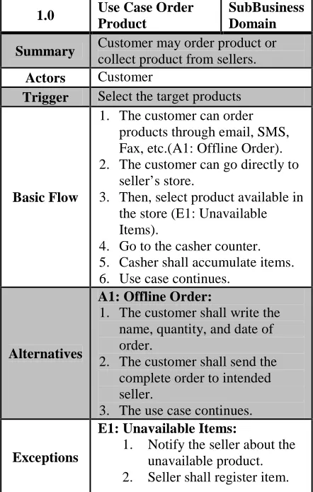
[image:5.612.312.523.283.474.2]The next step is to describe use case each use case process. For example the description for Order Product is shown in Table 1:
Table 1: Use Case Description for Order Product.
1.0 Use Case Order Product
SubBusiness Domain
Summary Customer may order product or
collect product from sellers.
Actors Customer
Trigger Select the target products
Basic Flow
1. The customer can order
products through email, SMS, Fax, etc.(A1: Offline Order).
2. The customer can go directly to
seller’s store.
3. Then, select product available in
the store (E1: Unavailable Items).
4. Go to the casher counter.
5. Casher shall accumulate items.
6. Use case continues.
Alternatives
A1: Offline Order:
1. The customer shall write the
name, quantity, and date of order.
2. The customer shall send the
complete order to intended seller.
3. The use case continues.
Exceptions
E1: Unavailable Items:
1. Notify the seller about the
unavailable product.
2. Seller shall register item.
3. Use case continues.
Post Condition
The target product selected and ordered successfully.
Create Class diagrams: From the use case
descriptions, we can identify that this particular subdomain has (User, Seller, Customer, Products, Delivery, Payment, Order, Stock Management, Product Catalog) classes. The class diagram for these classes is shown in Figure 8.
UpdateP() getP() Pname PID pCat PDoE Products LogPayment() Mtype() ValidateT() TID Tdate Ttotle TDetails Payment CheckOrder() OrderStaus() getOrder() OrID OrDate Or_to_add OrTTL OrStatus Order ChangePStatus() ReserveP() CheckItem() PID Pquantity Remark StockManager AddCat() updateCat() PCname PCID Cat ProductCataloge * * -1 * -1..* * -1 * -1 * Ustatus() ValidateUser() CheckType() UID PWD Status User ManageP() ManageProfile() Fname LName Add Phone Seller 1 * orderP() ManageProfile() Fname LName Add Phone Customer 1 * 1..* 1 1..*1 updateItemQty() changeOrStatus() OrID PID DoOr DoDelv DelvAdd DelvID Delivery 1..* 1 1 * 1 1
Figure 8: the subdomain class diagram
4.3 BLOCK ANALYSIS
Here the block analysis will take place. Where the use case scenarios identified and the alternative and exceptions as will, then the relationship between use case and classes will identify the strong relationship in order to cluster the strong relationship in the same block
Identify Scenarios: In this step the alternative
[image:5.612.84.305.386.733.2]ISSN: 1992-8645 www.jatit.org E-ISSN: 1817-3195
Table2. Block Identification.
Actor Use Case Alt, Exp,
CRU D
Relationsh ip
Seller
Capture
Deals 1
Process Payment
Exceptio
n 3 Exception
Display
Info. 1
Calculate
Tax 1
Billing 1
Supplier
View
Order 1
Check
Stock 1
Deliver
Product 3
Customer
Process
Payment Alt 3 Alternative
Order
Product 3
Acknowl
edge 3
Identify Process Flow: The sub domain process
flow is designed to identify the possible paths as shown in the following Figure 10.
Figure 10: sub domain process flow
Identify Relationship Using CRUD Matrix:
Here the relationship between classes and use case is identified through a CRUD Matrix, based on the strong relationship the classes’ clustering is
achieved. The following Table 3 shows that, the class repeated in the same task and crossed different use case are circled with oval shape as shown in figure 3. Thus, class (order, seller, customer, Stock) has repeated cross more than one use case. Therefore, the four classes represent strong relationship cross the use cases is analyzed. The remaining classes which cross different use case in different tasks can be grouped at the end, such as Product class which highlighted in doted rectangle. Finally, the other classes joined based on their use case.
Table3. CRUD Matrix.
T
a
sk
Classes Cu
st
o
m
er
O
rd
er
P
ro
d
u
ct
P
a
y
m
en
t
U
se
r
S
to
ck
se
lle
r
P
ro
d
u
ct
C
a
ta
lo
g
Use cases
1 Capture Deals
X X X
X
1 Process
Payment X X X X
1 Display
Info X
1 Calculat
e Tax X
1 Billing X
2 View
Order X X
2 Check
Stock X X
2 Deliver
Product X X
3 Process
Payment X X X X
3 Order
Product X X
3 Acknow
ledge X X
Identify Blocks: The previous table 3 illustrate
the relationship between use cases and classes, thus, the use case sharing the same classes can be grouped together. Therefore, the blocks identified are Capture deals, Process Payment, Manage Product, and Manage Order.
Create the block requirement specification:
ISSN: 1992-8645 www.jatit.org E-ISSN: 1817-3195
[image:7.612.259.511.49.684.2]
document describing the use case diagram and description, properties, behavior and contract type. The block requirement specification for Capture Deals is described in Table 4, Figure 11, and Table 5 as below.
Table 4: Block Requirement Specification
Block Name
Capture Deals
Block Id B-E-C-10001
Contract Type
Sequential
Actors Seller
Properties Background, printer, font-Color. Features Change printer, change text color,
change Tax schema, and switch to invoice option.
Use Cases Capture Deals, Display sales info, and calculate Tax.
Remark The switch invoice option should be enabled at run time.
Capture Deals
Seller
Billing
Extends Display Sales
information
Extends Calculate Totals
& Tax
[image:7.612.90.301.163.445.2]Extends
Figure 11: Block Capture Deals Use Case Diagram
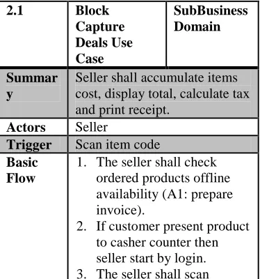
Figure 5 represents the use case diagram for block identified “Capture Deals”. The use case is refined and its description is shown in Table 5.
2.1 Block
Capture Deals Use Case
SubBusiness Domain
Summar y
Seller shall accumulate items cost, display total, calculate tax and print receipt.
Actors Seller
Trigger Scan item code
Basic Flow
1. The seller shall check
ordered products offline availability (A1: prepare invoice).
2. If customer present product
to casher counter then seller start by login.
3. The seller shall scan
product (E1: unregistered barcode).
4. The seller display items
details (E2: Cancel Item).
5. Seller shall accumulate
items cost.
6. The Calculator adds
automatically the tax percentage based on standard tax enabled.
7. Repeat step 3,4 & 5 until
items finish.
8. Seller Display total cost.
9. The seller click/ press
finish button.
10.The invoice is generated
automatically.
11.The bill is printed (E3:
Printing Error).
12.Use case continues.
Alternat ives
A1: Prepare invoice:
1. The seller shall write the
details of the product invoice.
2. The seller shall
acknowledge the customer with invoice of delivery.
3. The use case continues.
Exceptio ns
E1: unregistered barcode
1. If item code cannot be
scanned, Seller shall key in the item number.
2. Use case continues.
E1: Cancel Item
1. If item cancelled, the seller
shall remove item from list.
2. The total cost updated.
3. The Use case continues.
E3: Printing Error:
1. The error source is
displayed.
2. The activity log is
registered.
3. Use case continues.
Post Conditio n
The target products captured and the total cost displayed including Tax and receipt is printed.
7 CONCLUSIONS
[image:7.612.91.278.526.726.2]ISSN: 1992-8645 www.jatit.org E-ISSN: 1817-3195
are the three steps involved in this phase: (i) Domain Analysis (ii) Subdomain Analysis, (iii) and finally the Block Analysis. In this paper we have shown the feasibility of the methodology through a case study. In the case study, the process of domain analysis, subdomain analysis and block analysis have been described. Finally the required blocks for a particular subdomain have been identified.
REFRENCES:
[1] S. N. Sarif, S. Idris, and A. M. Zin, "The design of blocks integration tool to support end-user programming," in Electrical Engineering and
Informatics (ICEEI), 2011 International
Conference on, 2011, pp. 1-5.
[2] A. M. Zin, "Block-Based Approach for End-User Software Development," Asian Journal of Information Technology, vol. 10, pp. 249-258, 2011.
[3] A. Ismail, N. Omar, and A. Mohd Zin, "Developing learning software for children with
learning disabilities through Block-Based
development approach," in Electrical
Engineering and Informatics, 2009. ICEEI'09. International Conference on, 2009, pp. 299-303. [4] S. Mahmood, R. Lai, and Y. S. Kim, "Survey of
component-based software development,"
Software, IET, vol. 1, pp. 57-66, 2007.
[5] D. Birkmeier and S. Overhage, "On component identification approaches–classification, state of the art, and comparison," Component-Based Software Engineering, pp. 1-18, 2009.
[6] Z. Wang, X. Xu, and D. Zhan, "A survey of business component identification methods and related techniques," International Journal of Information Technology, vol. 2, pp. 229-238, 2005.
[7] S. D. Kim and S. H. Chang, "A systematic method to identify software components," 2004, pp. 538-545.
[8] Z. Cai, X. Yang, X. Wang, and Y. Wang, "A systematic approach for layered component identification," 2009, pp. 98-103.
[9] M. S. Choi and E. S. Cho, "A component identification technique from object-oriented
model," Computational Science and Its
Applications–ICCSA 2005, pp. 117-130, 2005. [10] M. Choi and E. Cho, "Component identification
methods applying method call types between classes," Journal of information science and engineering, vol. 22, p. 247, 2006.
[11] C. Kobryn, "UML 2001: a standardization odyssey," Communications of the ACM, vol. 42, pp. 29-37, 1999.
[12] K. C. Kang, S. G. Cohen, J. A. Hess, W. E. Novak, and A. S. Peterson, "Feature-oriented domain analysis (FODA) feasibility study," DTIC Document1990.
[13] K. C. Kang, S. Kim, J. Lee, K. Kim, E. Shin, and M. Huh, "FORM: A feature-; oriented reuse method with domain-; specific reference architectures," Annals of Software Engineering, vol. 5, pp. 143-168, 1998.
[14] K. C. Kang, J. Lee, and P. Donohoe, "Feature-oriented product line engineering," Software, IEEE, vol. 19, pp. 58-65, 2002.
[15] M. L. Griss, J. Favaro, and M. d'Alessandro, "Integrating feature modeling with the RSEB," in Software Reuse, 1998. Proceedings. Fifth International Conference on, 1998, pp. 76-85. [16] S. D. Lee, Y. J. Yang, F. S. Cho, S. D. Kim, and
S. Y. Rhew, "COMO: A UML-based
component development methodology," in
Software Engineering Conference,
1999.(APSEC'99) Proceedings. Sixth Asia Pacific, 1999, pp. 54-61.
[17] R. Ganesan and S. Sengupta, "O2BC: A technique for the design of component-based applications," in Technology of Object-Oriented Languages and Systems, 2001. TOOLS 39. 39th International Conference and Exhibition on, 2001, pp. 46-55.
[18] G. Booch, J. Rumbaugh, and I. Jacobson, Unified Modeling Language–User’s Guide: Addison-Wesley Reading, MA, 1999.
[19] B. Selic, "Using UML for modeling complex real-time systems," 1998, pp. 250-260.
[20] I. Jacobson, "The use-case construct in object-oriented software engineering," Scenario-based design: envisioning work and technology in system development, pp. 309-336, 1995. [21] S. W. Ambler and M. Lines, Disciplined Agile