Study on Earth Surface Potential and DC Current
Distribution around DC Grounding Electrode
Zhi-chao Ren, Chun-yan Ye, Hai-yan Wang
1Planning &evaluation center, Sichuan Power Economic Research Institute, Chengdu, China 2Equipment condition assessment center, Sichuan Electric Power Research Institute, Chengdu, China
Email: [email protected]
Received April, 2013
ABSTRACT
DC magnetic biasing problem, caused by the DC grounding electrode, threatened the safe operation of AC power grid. In this paper, the characteristics of the soil stratification near DC grounding electrode was researched. The AC-DC in-terconnected large-scale system model under the monopole operation mode was established. The earth surface potential and DC current distribution in various stations under the different surface thickness was calculated. Some useful con-clusions are drawn from the analyzed results.
Keywords: DC Grounding Electrode; Magnetic Biasing; Soil Stratification; Earth Surface Potential; DC Current Distribution
1. Introduction
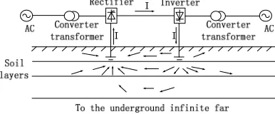
From an economic point of view, at the first stage of construction, domestic HVDC transmission project often put into an electrode firstly, as shown in Figure 2. At this point, DC flowed through the grounding electrode into the earth, and its breadth and depth of the diffuser was still an open. However, the negative effects of this opera-tion mode had been a consensus[1-18], mainly the fol-lowing three points: electromagnetic effect, thermal ef-fect and eletrochemical efef-fect. In this paper, the surface potential distribution was a kind of electromagnetic ef-fects. In this commissioning and operation of DC trans-mission system, these problems really existed. Therefore, the study of surface potential and DC current distribution was of great significance.
2. Calculation Model
[image:1.595.366.483.489.599.2]Take the Shanxi-Jiangsu ± 500 kV DC transmission line project for example, which was from ± 500 kV HVDC converter station (in Yangcheng county, shanxi prov-ince)to another one(in Liyang, Jiangsu province).
Figure 1. The monopolar ground circuit operation mode
2.1. Location Coordinate
[image:1.595.381.464.635.720.2]The relative position of each station in AC-DC intercon-nected power system was demarcated in the form of rec-tangular coordinate, as shown in Figure 3. Gaoping DC grounding electrode was located in Jincheng city, Shanxi province. The position of this electrode was considered as the origin of coordinate, with the radius of 100km as the research scope.
Figure 2. AC-DC interconnected system location coordinate diagram.
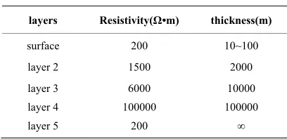
[image:1.595.75.268.643.723.2]2.2. Soil Stratification Structure
Soil surface with low resistivity was usually very shallow. Below the surface was the salt soil layer, which the resis-tivity was up to thousands of Ω•m. Then it reached to the rock, with the resistance rate was up to 100000 Ω•m above and the thickness was about hundred km. The re-sistivity of the lower crust began to decrease, which was only 200 Ω•m or less; Corresponding to 100-200 km depth, the resistivity of low-velocity layer was 10 Ω•m. In the depth of 400-650 km, the resistivity in turn drasti-cally reduced to 1 Ω•m. The resistivity of the lower man-tle was only 0.1 Ω•m in the depth of 1500 km[19-21] .
The loess layer in southeast of Shanxi was thinner, mostly about 50 meters[22], and the thickness of various regions was uneven , therefore, it should select different thickness values when calculated, which were as fol-lows:100 meters, 50 meters, 10 meters. Based on the typical reference value, the loess resistivity was defined as 200 Ω•m. The soil in Jindongnan area was divided into five layers, as can be seen in Table 1.
2.3. DC Power System
The full-length of HVDC transmission lines was 865.45 km, of which the Shanxi segment was 45 km, and Jin-cheng grounding electrode line was 80 km. The overlook and view of DC double-ring grounding electrode were shown in Figure 4.The large ring with a radius of 400m, the small ring with a radius of 300 m. Grounding con-ductor was made of round steel materials, whose radius was 35 mm. With 8 cables, the current, from the current injection points, was introduced into the grounding ring. The cable was made of copper, and its cross- sectional area was 240 mm2, which was 0.1 m high from the
ground. The grounding electrode was 3 m below the ground. The center of which was located in the Gaoping area of Jincheng. Current injection segment was made of copper wire, and the cross-sectional area: 240 mm2×
8=1920 mm2.
2.4. AC Power Grid
[image:2.595.319.529.86.257.2]AC system mainly includes substations, AC grounding nets and HVAC transmission lines. According to the
Table 1. The soil stratification.
layers Resistivity(Ω•m) thickness(m)
surface 200 10~100
layer 2 1500 2000
layer 3 6000 10000
layer 4 100000 100000
[image:2.595.69.273.631.730.2]layer 5 200 ∞
Figure 4. The view of earth surface potential.
importance of substations,1000 kV, 500 kV and 220 kV substations, which are located in the scope of 100 km radius from Gaoping DC grounding electrode, were stu-died. The equivalent DC resistance of transmission line was decided by wire type, length, division number and loop number.
3. Results Analysis
In this paper, the station with symbol “■” was ±500kV converter station. The station with symbol “▲” was 1000kV substation. The stations with symbol “●” were 500kV substations. Others without symbol were 220kV substations.
3.1. Earth Surface Potential
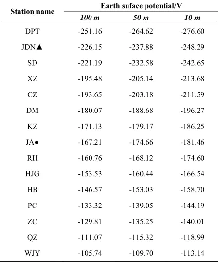
As shown in Table 2, Table 3 and Figure 5, with the different thickness of loess, the surface potential was difference. the value of Dc grounding electrode was -1489.2 V, -1894.3 V and -2529.6 V. The value of con-verter station was -173.73 V;-181.94 V and -189.18 V. The value of 1000 kV UHV AC station was -226.15 V; -237.88 V and-248.29 V.
The value of 500 kV and 220 kV was about from -550 V to -100 V.
Take the surface soil thickness 10m for example, the closer to the distance from DC grounding electrode, the larger of the step voltage. It ranges from 0 to 1 km. The potential decreased to 1.251 V of the average per pa-rameter, and the largest step voltage was about 1.6 V, which was lower than the largest safety limit value 2.5 V prescribed by the Chinese government.
3.2. DC Current Distribution
DC current distribution at station in the city Jincheng and Changzhi were as shown in Table 4 and Table 5. The
Table 2. Earth surface potential AT STATION in Jincheng city.
Earth suface potential/V Station name
100m 50m 10m
DC electrode -1489.2 -1894.3 -2529.6
SN -485.23 -517.93 -547.50
JC● -468.51 -499.47 -527.26
DH -443.30 -471.79 -497.12
BYC -336.39 -356.01 -373.49
LC -312.57 -330.47 -346.43
DG -236.05 -248.46 -259.48
JS -232.79 -245.00 -255.83
QD -216.35 -227.39 -237.13
FC -188.64 -197.85 -205.98
YCB● -176.68 -185.07 -192.50
YC■ -173.73 -181.94 -189.18
QC -169.62 -177.54 -184.50
Table 3. Earth surface potential AT STATION in Changzhi city.
Earth suface potential/V Station name
100 m 50 m 10 m
DPT -251.16 -264.62 -276.60
JDN▲ -226.15 -237.88 -248.29
SD -221.19 -232.58 -242.65
XZ -195.48 -205.14 -213.68
CZ -193.65 -203.18 -211.59
DM -180.07 -188.68 -196.27
KZ -171.13 -179.17 -186.25
JA● -167.21 -174.66 -181.46
RH -160.76 -168.12 -174.60
HJG -153.53 -160.44 -166.54
HB -146.57 -153.03 -158.70
PC -133.32 -139.05 -144.19
ZC -129.81 -135.25 -140.01
QZ -111.07 -115.32 -118.99
WJY -105.74 -109.70 -113.14
[image:3.595.312.532.115.310.2]When the surface soil thickness was considered as 100 m,50 m,10 m respectively, the inflow DC current could respectively reach 1.2 A、1.4 A、1.4 A at the Yangcheng converter transformer side, and the outflow DC current of the Jindongnan 1000 kV substation could respectively reach 2.2 A、2.3 A、2.8 A.The largest influence subtations of DC grounding current were Shengnong, Jincheng, Danhe and Beiyicheng.
Table 4. DC current distribution AT STATION in Jincheng city.
DC current amount/A Station name
100m 50m 10m
SN -19.7 -21.1 -22.0
JC● -18.3 -19.6 -20.4
DH -17.0 -18.3 -19.0 BYC -10.0 -10.6 -11.0
LC -8.2 -8.7 -9.0 DG -2.9 -3.1 -3.2 JS -2.8 -2.9 -3.0
QD -1.7 -1.8 -1.8
FC +0.2 +0.27 +0.31
YCB● +1.0 +1.1 +1.2
YC■ +1.2 +1.4 +1.4
QC +1.6 +1.7 +1.8
Table 5. DC current distribution AT STATION in Changzhi city
DC current amount/A Station name
100 m 50 m 10 m
DPT -4.1 -4.3 -4.4
JDN▲ -2.2 -2.3 -2.8
SD -2.0 -2.1 -2.2
XZ -0.17 -0.15 -0.13
CZ -0.23 -0.16 -0.18
DM +0.72 +0.85 +0.86
KZ +1.4 +1.6 +1.6
JA● +1.7 +1.9 +2.0
RH +2.0 +2.2 +2.2
HJG +2.5 +2.7 +2.8
HB +3.1 +3.3 +3.4
PC +4.0 +4.2 +4.4
ZC +4.1 +4.4 +4.6
QZ +5.4 +5.8 +6.0
WJY +5.8 +6.2 +6.4
[image:3.595.313.537.348.631.2] [image:3.595.60.285.361.630.2]Figure 6. DC current distribution in AC transmission lines of Jincheng city.
Figure 7. DC current distribution in AC transmission lines of Changzhi city.
4. Conclusions
The smaller the thickness of the surface soil is, the greater the absolute value of earth surface potential. The farther away from the grounding electrode, the smaller the absolute value of the surface potential, which formed the exponential decay function and tended to zero gradu-ally.
The DC current amount of the distal substation was not always less than the recent substaion. The DC current would select the pathway of which the DC resistance was the minimum. The DC current, flowing through the sub-station, of which the topological structure was more com-licated, was relatively large. The soil sructure had some influence on the DC current distribution: the smaller of the surface soil thickness, the larger of DC grounding current influence on the AC system.
5. Acknowledgements
The authors would like to acknowledge Shanxi Electric Power Corporation for the facilities provided during this research.
REFERENCES
[1] J. E. Villas and C. M. Portela, “Soil Heating around the Ground Electrode of an HVDC System by Interaction of Electrica, Thermal,and Electroosmotic Phenomena,”
IEEE Transactions on Power Delivery, 2003,Vol. 18, No. 3, pp. 874-881.
[2] B. Zhang, J. Zhao, R. Zeng et al., “Estimation of DC
current Distribution in AC Power System Caused by HVDC Transmission System in Ground Return Status,”
Proceedings of the CSEE, 2006, Vol. 26, No. 13, pp. 84-88.
[3] Z. C. Ren, G. N. Wu, W. Zhen, C. Wu and Y. Zhang, “Model Simplication and Calculation Method Analysis About the Shunt of DC Grounding Current Via AC Grid,” High Voltage Engineering, 2011, Vol. 37, No. 4, pp. 1008-1014.
[4] Z. H. Re, J. G. Xu, Y. K. Zhang, W. Zhen and G. N. Wu, “Study of the Simple Formula of DC Surface Potential in AC-DC Interconnected Large Power System," Transac-tions of China Electrotechnical Socitey,2011, Vol. 26, No. 7, pp. 256-263.
[5] W. Jiang, Z. Huang, C. Hu, Zhu, K. Wu, L. R. Zhou and Z. C. Ren, “Optimized Network Configuration of Small Resistances to Limit DC Bias Current of Transformers,”
Proceedings of the CSEE, 2009, Vol. 29, No. 16, pp. 89-94.
[6] X. H. Chi and Y. J. Zhang, “Protective Distance between HVDC Electrode and Underground Metal Pipeline,"
Power System Technology, 2008, Vol. 32, No. 2, pp.
71-74.
[7] M. X. Wang and Q. Zhang,“Analysis on Influence of Ground Electrode Current in HVDC on AC Power Net-work,” Power System Technology, 2005, Vol. 29, No. 3, pp. 9-14.
[8] J. Guo, J. Zou, J. L. He, et al., “Recur-sive Method to
obtain Analytic Expressions of Green’s Functions in Multi-layer Soil by Computer,” Proceedings of the CSEE,
2004, Vol. 24, No. 7, pp. 101-105.
[9] E. F. Fuchs, Y. You and D. J. Roesler, “Modeling and Simulation,and Their Validation of Three-phase Trans-formers with Three Legs under DC Bias,” IEEE Transac-tion on Power Delivery, 1999, Vol. 14, No. 2, pp.
443-449.doi:10.1109/61.754087
[10] L. S. Zeng, “Impact of HVDC Ground-ing Electrode Current on the Adjacent Power Transformers,” High Volt-age Engineering,2005, Vol. 31, No. 4, pp. 57-59. [11] L. H. Zhong, P. J. Lu, Z. C. Qiu, et al., “The Influence of
Current of DC Earthing Electrode on Directly Grounded Transformer,” High Voltage Engineering, 2003, Vol. 29, No. 8, pp. 12-13.
[12] C. Shang, “Measure to Decrease the Neutral Current of the ac Transformer in HVDC Ground-return System,”
[image:4.595.80.266.284.462.2]52-54.
[13] D. Z. Kuai, D. Wan and Y. Zhou, “Analysis and Handling of the Impact of Geomagnetically Induced Current upon Electric Network Equipment in DC Transmission,” Auto-mation of Electric Power Systems, 2005, Vol. 29, No. 2,
pp. 81-82.
[14] X. P. Li, S. X. Wen, L. Lan, Y. Zhang, Y. D. Fan, Z. X. Liu and L. Guo, “Test and Simulation for Single phase-Transformer Under DC Bias,” Proceedings of the CSEE,2007, Vol. 27, No. 9, pp. 33-40.
[15] J. Z. Sun and L. Liu, “Derivation of Greens Function by Equivalent Complex Image Method in a Horizontal and Vertical Combined-layer Soil Structure,” Proceedings of the CSEE, 2003, Vol. 23, No. 9, pp. 143-151.
[16] J. M. Lu, D. Xiao, C. X. Mao and G. H. Mei, “Analysis of Effects of DC Earthed Pole on Earth Surface Potential Distributions,” High Voltage Engineering, Vol. 32, No. 9, 2006, pp. 55-58.
[17] D. Kovarsky, L. J. Pinto, C. E. Caroli, et al., “Soil
Sur-face Potentials Induced by ITAIPU HVDC Ground
Re-turn Current Part I-theoretical Evaluation,” IEEE Trans-actions on Power Delivery, 1988, Vol. 3, No. 3, pp. 1204-1210.doi:10.1109/61.193904
[18] J. E. T. Villas and C. M. Portela, “Calculation of Electric Field and Potential Distributions into Soil and Air Media for a Ground Electrode of a HVDC System,” IEEE Trans.on Power Delivery, 2003, Vol. 18, No. 3, pp.
867-873.doi:10.1109/TPWRD.2003.809741
[19] W. Ruan, J. Ma, J. liu and F. P. Dawalibi, “Performance of HVDC Ground Electrode in Various Soil Structures,”
Power System Technology, Proceedings, International Conference, Vol. 2, 2002, pp. 962-968.
[20] J. W. Teng, “Solid Geophysics Conspectus,” Beijing, Earthquake Publishing House, 2003, Vol. 2, No. 1. [21] H. Xu, X. S. Wen, X. Shu, Q. S. Zhou and W. Deng,
“New Method of Computing Soil Parameters,” High-VoltageEngineering,2004, Vol. 30, No. 8, pp. 17-19.