Synthesis and Surface Modification of Spindle-Type
Magnetic Nanoparticles: Gold Coating and PEG
Functionalization
Juan Mendez-Garza1, Biran Wang1, Alexandra Madeira1, Christophe Di Giorgio2, Georges Bossis1
1Laboratoire de Physique de la Matière Condensée, UMR 7336, Université de Nice-Sophia Antipolis, CNRS, Parc Valrose, Nice,
France; 2Institut de Chimie de Nice, UMR 7272, Université de Nice-Sophia Antipolis, CNRS, Parc Valrose, Nice, France.
Email: [email protected], [email protected]
Received April 8th, 2013; revised May 26th, 2013; accepted June 10th, 2013
Copyright © 2013 Juan Mendez-Garza et al. This is an open access article distributed under the Creative Commons Attribution Li- cense, which permits unrestricted use, distribution, and reproduction in any medium, provided the original work is properly cited.
ABSTRACT
In this paper, we describe the synthesis of gold coated spindle-type iron nanoparticles and its surface modification by a thiolated fluorescently-labelled polyethylene glycol (PEG) polymer. A forced hydrolysis of ferric salts in the presence of phosphate ions was used to produce α-Fe2O3 spindle-type particles. The oxide powders were first reduced to α-iron
under high temperature and controlled dihydrogen atmosphere. Then, the resulting magnetic spindle-type particles were covered by a shell of gold. The formation of the core@shell structure was driven by a redox-transmetalation reaction between iron(0) at the surface of particles and a gold(III) salt. Protected against oxidation, the Fe@Au core@shell nanoparticles were then grafted with a water soluble fluorescent-PEG-thiol. TEM, XRD, EDX and measurements of magnetic properties of particles confirm 1) the conversion of hematite into iron and 2) their subsequent surface protec- tion with a gold shell. Furthermore, the functionalization of the gold nanoparticle surface with a PEG carrying a fluo- rescent dye was unambiguously attested by confocal laser scanning microscopy.
Keywords: Core@shell; Spindle-Type; Hematite; Magnetic Particles; Gold Coating; Fluorescent-PEG
1. Introduction
Over the last decade, many reports have been devoted to the development of new generations of ferric oxide col- loids and magnetic nanoparticles, these nano-objects have very attractive properties, which has resulted in a strong demand on several domains as microelectronics, catalysis, water treatment, including applications as MRI- traceable drug carriers, cancer cell inhibitors or tumor cell magnetolysis agents [1,2]. In particular, special at- tention has been paid to the formulation of nanoparticles with controlled morphology and narrow size distributions. In the case of hematite (α-Fe2O3), one-dimensional nano-
structures with different morphologies such as wire-like, rod-like and belt-like or two-dimensional spherical, elon- gated (spindle), micro-ring, or pseudo-cubic ones have been elaborated. They are produced by forced hydrolysis of ferric salts. In general, the growth of monocristalline
α-Fe2O3 takes from a few days using hydrothermal tech-
niques to one week under forced hydrolysis at 100˚C [3]. The anisotropic growth of hematite is generally con-
trolled by the presence of different anions like phos- phates, sulfates, oxalates or hydroxide ions [4-6]. Hema- tite is also used as a raw material to produce metallic iron with high magnetic properties. The reduction of α-Fe2O3
to α-Fe(0) takes place at roughly 400˚C under a H2 at-
mosphere. The main challenge in hematite reduction at high temperature is the aggregation of particles, mainly provoked by the sintering phenomenon that occurs at the interfaces between particles. Furthermore, to prevent un- controlled re-oxidation of iron, passivation techniques are used. The passivation of metal powders is typically done by growing an oxide layer over the surface of particles, covering its surface with a silica layer or with an inert metallic shell (gold, silver, platinum) creating core@shell structures [7-9]. Passivation of nanoparticles is also re- quired for biocompatibility when in vivo biomedical ap- plications are contemplated.
metalation reaction (Scheme 1). Due to their ellipsoidal
morphology and biocompatibility rendered by the gold passivation, magnetic Fe@Au NPs may have a tremen- dous potential for cancer therapy thanks to tumor cell magnetolysis process [10,11]. Aiming at this goal, we have functionalized their surface with polyethylene gly- cols (PEG), which is an important biocompatible poly- mer that facilitates the solubilization and long-term cir- culation of proteins, viruses and other biological macro- molecules [12]. We have then functionalized PEGs by substituting both terminal hydroxyl groups with respec- tively a thiol group (SH) and a fluorescein tag thanks to fluorescein isothiocyanate (FITC), (Scheme 1). The re-
sulting bi-functionalized molecule was grafted to NPs throughout the strong gold-thiol covalent bond and con- sequently the fluorescein tag gave to particles an optical contrast that could facilitate observations of treated cells by confocal microscopy in the case of magnetolysis the- rapy. It is nevertheless important to note that the surface labeling can be easily adapted providing specific target- ing of cancer cells by tethering ligands such as folic acid, RGD peptides or growth factor (e.g. VEGF) ligands at the PEG extremity in place of the fluorescent dye. Al- though spindle-type Fe@Au nanoparticles have already been described, the displacement reaction of iron by gold without the need of any additional agent, i.e. reducing agents or microemulsion became an interesting option for the preparation of spindle-type Fe@Au core@shell nano- particles [13-15].
Scheme 1. General procedure to obtain the pegylated iron@gold (core@shell) NPs.
2. Experimental Section
2.1. Chemicals
Reactions were carried out under inert atmosphere using appropriate techniques. Iron(III) chloride hexahydrate (FeCl3·6H2O), trichloroethylene (C2HCl3), 1,2 dichloro-
benzene (DCB), tetraoctylammonium bromide (TOAB) [C8H17]4N+ Br−, and auric acid (HAuCl4) were supplied
by Sigma-Aldrich. H2N-PEG5000-STrt (α-amino-ω-trityl-
thio-poly(ethylene glycol) Mw = 5000 Dalton) was sup- plied by IRIS Biotech GMBH. Sodium phosphate mo- nobasic (NaH2PO4) was supplied by Fluka. Ultra pure
water 18.2 MΩ cm was obtained from a Thermo Scienti- fic water purification device.
2.2. Characterization Techniques
The polyethylene glycol was verified by nuclear mag- netic resonance (1H NMR, Bruker AC-200 MHz spec-
trometer). Structure and properties of iron and hematite were studied by X-ray diffractions (XRD, Bracket PW307) at 45 kV and 30 mA. The instrument used a Cu Kα radiation with a wavelength of 1.54060 Å, samples were placed in a glass holder and were scanned from 6 to 110˚, 2θ), transmission electron microscopy (TEM, JEOL JEM-1400), scanning electron microscopy (SEM, FEI XL30 ESEM LaB6) coupled to an energy dispersive ana- lyzer (EDX, EDX Oxford/INCA). Surface modification of particles with the fluorescent polymers was analyzed with a Leica SPE confocal microscope using a 63 × 1.4 N.A. oil immersion objective. Magnetic properties of sam- ples were investigated using a M2000/2100 hysteresis meter.
2.3. Synthesis of Hematite Spindle-Type Particles
The preparation of α-Fe2O3 particles was performed ac-
cording to a method, which has been described elsewhere [4,16] and adapted for a larger scale (5 - 10 g) synthesis. Briefly, 5.41 g (0.02 M) of FeCl3·6H2O and 0.054 g (0.45
mM) of NaH2PO4 were dissolved in 1 L of ultra pure
water and kept undisturbed during 6 days at 100˚C. Then, a filtration method to wash off sub-products (mainly salts) of hematite suspensions was applied.
2.4. Hematite Reduction to Iron(0)
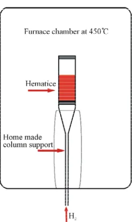
The non-agglomerated hematite powders (10 g) obtained above was calcinated in a modified furnace chamber at 450˚C under a continuous H2 flow (0.5 L min−1) during 4
h. The temperature was controlled by a PID-controller included in the tube furnace (Pirox). The vertical tube furnace was modified to introduce a vertical column sup- port adapted to spread H2 through the sample (Scheme 2).
The home-made column support came from a modified Pirex buchner filter funnel lengthen in bottom. The colu- mn incorporated a sintered silica distributor in bottom, and a quartz wool was placed on top to prevent the flui- dized powder to escape from the column.
The whole particles turned from reddish to black in- dicating conversion of Fe(III) into Fe(0). After cooling under a N2 stream, the column was pulled down and tri-
chloroethylene (20 mL) was added under N2 flow to
avoid oxidation of the resulting α-Fe(0) NPs, which were kept into this solvent for further experiments. Very inte- restingly, it should be mentioned that no sintering was observed during this step.
2.5. Surface Modification of Iron Particles
Synthesis of FITC-PEG5000-SH. H2N-PEG5000-STrt (250
mg, 0.05 mmol) was dissolved into CH2Cl2/DMF (5/1,
v/v) 600 µL and then FITC (19.5 mg, 0.25 mmol) and Et3N (50 µL, 0.5 mmol) were added. The mixture was
stirred overnight and diethyl ether was then added. The precipitated was filtered off, washed with ether and then dried over vacuo. S-Trityl protecting group was then re- moved with TFA to lead, after precipitation with diethyl ether, the desired thiol, Fluorescein-PEG5000-SH with
90% overall yield as a yellow-orange solid.
Scheme 2. Furnace scheme of α-Fe2O3 powders reduction.
NMR analysis of PEG. NMR 1H ( ppm, D
2O, 200
MHz): 2.3 - 2.65 (m, 4 H, CH2SH, CH2CONH), 3.11 -
3.38 (m, (CH2O, CH2NH, 310 H], 6.43 - 6.63 (m, 6 H, H
aromatic FITC), 7.02 (d, 1 H, J 8.1 Hz, H aromatic FITC), 7.57 - 7.62 (m, 1 H, H aromatic FITC), 7.80 - 7.83 (m, 2 H, H aromatic FITC).
Fe@Au NPs preparation. Gold coating of α-Fe(0)
NPs was adapted and performed according to a described procedure [17]. First, hydrophobized gold(III) salt [(C8H17)4N]+[AuCl4]− were obtained from a phase trans-
fer after mixing solutions of TOAB in DCB and aqueous HAuCl4 under vigorous stirring. [(C8H17)4N]+[AuCl4]−
(290 mg, 0.36 mmol) were dissolved into 20 mL of DCB and added 100 mg of NPs under N2 atmosphere, the mix-
ture were then heated at 90˚C for 2 h while kept under inert atmosphere and maintained under mechanical stir- ring. The reaction was quenched by adding 40 mL of ab- solute ethanol (EtOH). Fe@Au NPs were subjected to centrifugation/washing cycles with absolute EtOH (five times). Finally, particles were suspended into absolute EtOH and kept under a N2 atmosphere for further expe-
riments.
Surface modification of Fe@Au NPs. 500 µL of the
Fe@Au NPs stock suspension (10 mg·mL−1 in absolute
EtOH) were degassed. Then, 500 µL of freshly made flu- orescein-PEG5000-SH stock solution (10 mM in ultra pure
water), which was previously degassed and filtered (0.22 µm, cellulose acetate), was added under N2. The resulting
mixture was then stirred for 2 h under N2. Pegylated
Fe@Au NPs were purified by several centrifugation/re- suspension cycles into ultra pure water until the fluores- cence signal of discarded water reached background level. Finally, FITC-PEG5000-labelled Fe@Au NPs were sus-
pended into ultra pure water (1 mL) and further analyzed by TEM and confocal microscope to evidence functiona- lization.
3. Results and Discussion
3.1. Morphology and Structure of Hematite and Iron NPs
α-Fe2O3 and α-Fe(0) NPs resulting from the reduction
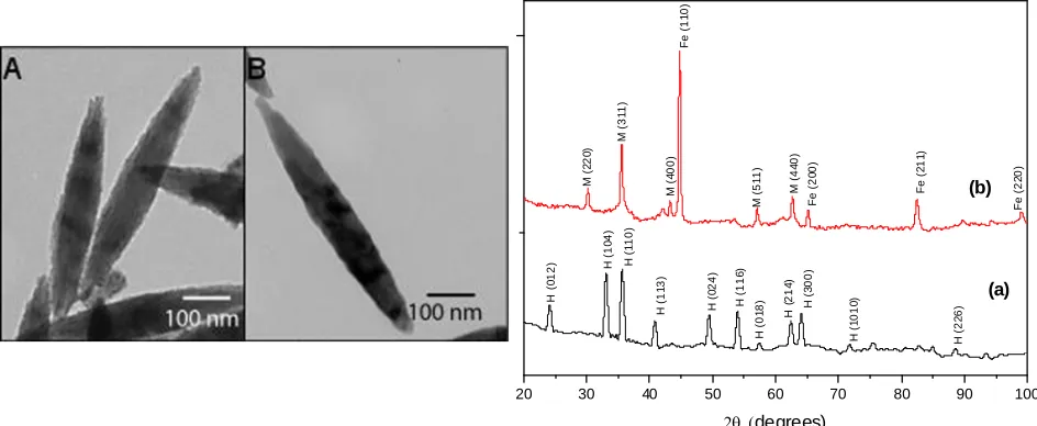
process were analyzed by TEM and X-ray spectroscopy. The morphology and dimensions of particles were eva- luated throughout a series of TEM pictures counting ap- proximately 200 particles. Figure 1 displays a typical
single particle of α-Fe2O3 (A) and α-Fe(0) NPs (B). It is
[image:3.595.106.239.496.719.2]important to mention that the shape of particles kept un- disturbed during the whole process of reduction of the oxide into a metal phase. The average sizes measured from the TEM pictures were 580 (± 50) nm in length and of 80 (± 5) nm in width.
Figure 1 presents also the XRD patterns of both hema-
20 30 40 50 60 70 80 90 100
Fe
(
2
2
0
)
Fe
(
2
1
1
)
Fe
(
2
0
0
)
M (4
4
0
)
M (5
1
1
)
Fe
(
1
1
0
)
M
(
4
00)
M (
3
1
1
)
M (
2
2
0
)
H (
2
2
6
)
H
(
1
010
)
H
(
3
00)
H
(
214
)
H (
0
1
8
)
H
(
116
)
H
(
0
24)
H (
1
1
3
)
H
(
1
10)
H (
1
0
4
)
degrees)
H
(
0
12)
[image:4.595.62.534.87.281.2](a) (b)
Figure 1. TEM pictures of (A) α-Fe2O3 and (B) α-Fe(0) NPs. X-ray diffraction patterns of α-Fe2O3 (a) and α-Fe(0) NPs (b),
where planar peaks are hematite (H), iron (Fe) and magnetite (M).
corresponding only to Hematite. Pattern (b) shows two main phases, iron and magnetite. In (b), the crystallite sizes were estimated using the Scherrer equation with the characteristic reflections corresponding to iron (110) and magnetite (311), and were evaluated to 23 and 20 nm respectively. [18] Further magnetization measurements (see Section 3.4) are conjugated to these values to quan- tify the magnetic part of particles.
[image:4.595.310.535.323.501.2] [image:4.595.309.539.543.708.2]3.2. Fe@Au NPs Structure
Figure 2 shows the X-ray diffraction pattern of Fe@Au
NPs. In this spectrum we have observed the characteristic peaks of iron, gold and magnetite, iron and gold peaks are overlapped at the diffractions peaks of 2 = 43.2˚, 62.7˚ and 82.43˚. Single peaks of gold and iron at 77.7˚
and 98.8˚ are respectively detected. It is as well observed the presence of magnetite as seen in Figure 1 (b). The
core-shell structures of iron and gold were also corro- barated by SEM-EDX microscopy, Figure 3 presents the
microanalysis of NPs presented in the inset of Figure 3.
The EDX spectrum exhibits peaks for Fe, O, P and Au. The presence of Phosphorus is due to the phosphate in- troduction during the synthesis of hematite, the weak gold signal is due to the thin gold coating shell (see next section). These studies carried out by and XRD and SEM-EDX illustrate the coating of Fe@Au NPs and de- monstrate that the presence of magnetite does not disturb the smooth reaction process, where a shell layer forma- tion and core metal consumption occur simultaneously between surface Fe atoms of α-Fe(0) NPs and Au(III) ions of [(C8H17)4N]+[AuCl4]− in a non aqueous solvent.
Figure 2. X-ray diffraction patterns of Fe@Au, where pla-nar peaks are iron (Fe), gold (Au) and magnetite (M).
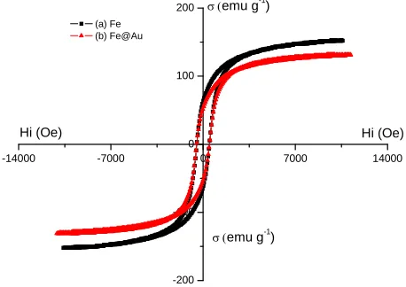
3.3. Magnetic Properties of Fe and Fe@Au NPs
Figure 3. EDX spectrum of Fe@Au NPs, inset SEM image of Fe@Au NPs.
zed by magnetization hysteresis loops at room tempera- ture (Figure 4) and Table 1 presents the results deter-
mined from these curves: saturation magnetization (Ms),
remanent magnetization (Mr), coercivity (Hc) and square-
ness ratio (Sr = Mr/Ms).
The ferromagnetic nature of the nanoparticles is char- acterized by the ratio of remanence to saturation magne- tization (Sr). Particular attention has been paid to the sa-
turation magnetization (Ms) parameter, which is defined
as the maximum of the magnetization value achieved in a sufficient large magnetic field. Table 1 shows that the
saturation magnetization of gold-coated Fe@Au NPs ( ) is lower than the value determined for non- coated α-Fe NPs powders ( ), as expected owing to
Fe@Au s M
Fe s M
the non magnetic gold shell constituting the Fe@Au NPs. However, both these Fe and values are lower
s
M Fe@Au
s M
than the Ms value reported in the literature for bulk iron
( bulk s
M = 222 emu·g−1) [19]. These differences are most
likely related to the presence of the residual oxide phase detected by XRD and EDX. Nevertheless these values of Ms are similar to those reported in literature for similar
spindle-type iron nanoparticles [4].
3.4. Magnetic Part and Gold Shell Thickness Quantification on NPs
Using the Ms values, one can calculate the magnetic and
non magnetic part in single magnetic NPs and conse- quently deduce the thickness of the gold shell on the
-14000 -7000 0 7000 14000
-200 -100 0 100 200
Hi (Oe)
emu g-1
)
emu g-1)
(a) Fe (b) Fe@Au
[image:5.595.58.287.462.624.2]Hi (Oe)
[image:5.595.57.285.680.737.2]Figure 4. Hysteresis loops of (a) α-Fe and (b) Fe@Au NPs.
Table 1. Magnetic properties of Fe and Fe@Au NPs de- termined from hysteresis loops.
Hc (Oe) Ms (emu·g−1) Mr (emu·g−1) Sr
Fe NPs 294 156 34.9 0.224
Fe@Au NPs 485 131 52.6 0.401
Fe@Au NPs. The magnetic moment (µ) of a particle (p) is given by: p
p s
V M p
, where Vp is the volume of
the particle, ρp its density and Msp its saturation mag-
netization. Applying this relationship to the bulk iron, one obtains thus the Equation (1):
sp
p bulk
bulk p bulk s
M V
V M
(1)
Applying this equation to the data measured on the
α-Fe NPs (Table 1 for the Ms values) and to the densities
found for ρp (= 5.3 ± 0.1 g·cm−3, experimenatlly deter-
minated) and bulk (= 7.86 g·cm−3, [19]), one obtains
0 47
bulk p
V . V . This indicates that 47% in volume (70% in mass) of the α-Fe NPs is magnetic, the other non mag- netic part being either voids or the residual phase formed during the reduction of the hematite.
For the calculation of the gold shell thickness (e), cov- ering the Fe@Au NPs, one can assume that e is related to the volume increment dV/V of the ellipsoidal particles, which is the total differential (Equation (2)) of the vol- ume of an ellipsoid:
2 4π 3
V a b (2) Assuming that the thickness e of the gold layer is ho- mogeneous in both a and b axes of the ellipsoid ( dadb e ), then the thickness of the gold layer is given by:
ab
de nm = 2 a + b
V V
(3)
dV/V is calculated from the magnetization of both Fe (Equation (4)) and Fe@Au NPs (Equation (5)) as follow:
Fe Fe s
Fe
N M
m
(4)
Fe @ Au
Fe @ Au Fe s
N M
m
(5)
where 1) Fe s
M and, Fe @ Au s
M 2) NFe and N'Fe and 3)
Fe
m and mFe@Au are the saturation magnetization, the number of Fe atoms, and the mass of one single Fe and Fe@Au particle, respectively.
Taking into account that the stoechiometry of the Fe/Au displacement reaction at the surface of the Fe par- ticle is of 1:1 (any single Fe(0) atom at the surface is oxidized into Fe(III) and is replaced by a single Au(0) atom resulting from the reduction of one Au(III) present in the solution), this indicates that N'Fe becomes equal to
NFe-NAu, where NAu is the number of Au atoms forming
no consequences onto the geometrical parameters (a, b and V) of the ellipsoid. Combining Equations (4) and (5) and replacing N'Fe by NFe-NAu, one obtains Equation (6):
1
1Fe Fe@ Au
Au s s
Fe Fe@ Au w w
Fe s s Au
N M M
N M M M M
Fe
(6)
where MwFe and MwAu are the molecular weight of iron
and gold, respectively.
Applying Equation (6) to the data measured on the
α-Fe and Fe@Au NPs (Table 1), one obtains the relation: Au
Fe
N dV
V = N the thickness of gold layer in the Fe@Au
NPs was then estimated to be of nearly 1.8 nm.
3.5. Pegylated Fe@Au NPs Characterization
By taking advantage of the high Au-S affinity, the gold surface of Fe@Au NPs was stained through chemisorp- tion with FITC-PEG5000-SH. Surface gold staining with
fluorescence was attested by confocal microscopy. Fig- ure 5 shows a 3D-picture constructed with ImageJ re-
corded from a Z-stack of 28 different views (longitudinal sections on the Z-axis) with the green emission mode (λem = 520 nm, λex = 490 nm). It should be noted that an
additional red emission mode (with λem = 620 nm, λex =
590 nm) was also tested as negative control (data not shown). This latter, as expected, could not result into any
Figure 5. Confocal microscopy 3D-picture of Fe@Au-S- PEG5000 (FITC) NPs in emission mode (green channel). The
bounding box displays xyz coordinate system as well as units (scale in µm).
red light emission. Green staining is only located at the surface of nanoparticles and clearly evidences their aci- cular shape. This experiment shows that Fe@Au NPs have been functionalized with the FITC-PEG-SH. It indi- cates also that PEG can provide dispersion of the Fe@Au NPs into aqueous media by creating a steric and hydro- philic shield. This strategy can be applied to functional- ize the surface of Fe@Au NPs for specific cell recogni- tion by tethering a suitable ligand at the PEG extremity.
4. Conclusion
In this paper, we demonstrated the feasibility to obtain highly disperse spindle-type hematite NPs and to reduce these into acicular metallic iron NPs under a H2 flow at
450˚C without sintering. By using a redox transmetala- tion process, the Fe core serves as a nanoelectrode for the spontaneous deposition of gold onto the surface of NPs without the need of any additional agent. From the com- parison of the saturation magnetizations, we have deter- minated that 70% (w/w) of particles are magnetic and the thickness of the gold layer was about 1.8 nm. The gold surface of the Fe@Au NPs was also functionalized with stained PEG thiol conjugates that provide dispersion of the Fe@Au NPs into aqueous media. Interestingly, the magnetic properties of Fe@Au NPs were only slightly lowered by the presence of the gold shell when compared to non passivated α-Fe NPs. This is important since fur- ther developments involving their mechanical action un- der alternative or rotating magnetic field are required to destabilize cell membrane of targeted cells. Studies in this field are currently in progress to use such Fe@Au NPs for specific cancer cell magnetolysis. This could be set by using PEG-ligand conjugates to selectively target specific receptors that are overexpressed onto cancer cells (VEGF, folate or integrin receptors for example). Other domains such as nanobiosensors or nanocarriers taking ad- vantages of their optic properties are still in development.
5. Acknowledgements
The authors gratefully acknowledge S. Pagnotta and J.P. Laugier for the TEM images. Authors thank P. Kuzhir and M. Lopez-Lopez for their comments on the manu- script; B. Wang is indebted to Region PACA and CNRS project BioMag for financial support. We also thank Pr J. Persello for his advices and technical help in the reduc- tion and coating of magnetic particles.
REFERENCES
[1] Y. N. Wu, D. H. Chen, X. Y. Shi, C. C. Lian, T. Y. Wang, C. S. Yeh, K. R. Ratinac, P. Thordarson, F. Braet and D. B. Shieh, “Cancer-Cell-Specific Cytotoxicity of Non-Oxi- dized Iron Elements in Iron Core-Gold Shell NPs,” Na-
7, No. 4, 2011, pp. 420-427. doi:10.1016/j.nano.2011.01.002
[2] M. Chen, S. Yamamuro, D. Farrell and S. A. Majetich, “Gold-Coated Iron Nanoparticles for Biomedical Appli- cations,” Journal of Applied Physics, Vol. 93, No. 10, 2003, pp. 7551-7553. doi:10.1063/1.1555312
[3] K. Kandori and T. Ishikawa, “Preparation and Microstruc- tural Studies on Hydrothermally Prepared Hematite,”
Journal of Colloid and Interface Science, Vol. 272, No. 1,
2004, pp. 246-248. doi:10.1016/j.jcis.2003.08.075 [4] T. Ishikawa and E. Matijevic, “Formation of Monodispers-
ed Pure and Coated Spindle-Type Iron Particles,” Lang- muir, Vol. 4, No. 1, 1988, pp. 26-31.
doi:10.1021/la00079a004
[5] M. Ocaña, M. P. Morales and C. J. Serna, “Homogeneous Precipitation of Uniform α-Fe2O3 Particles from Iron Salts
Solutions in the Presence of Urea,” Journal of Colloid
and Interface Science, Vol. 212, No. 2, 1999, pp. 317-323.
doi:10.1006/jcis.1998.6042
[6] X. L. Gou, G. X. Wang, J. Park, H. Liu and J. Yang, “Mo- nodisperse Hematite Porous Nanospheres: Synthesis, Cha- racterization, and Applications for Gas Sensors,” Nano-
technology, Vol. 19, No. 12, 2008, Article ID: 125606.
doi:10.1088/0957-4484/19/12/125606
[7] C. Baker, S. K. Hasanain and S. I. Shah, “The Magnetic Be- havior of Iron Oxide Passivated Iron Nanoparticles,”
Journal of Applied Physics, Vol. 96, No. 11, 2004, pp.
6657-6662. doi:10.1063/1.1806263
[8] E. E. Carpenter, S. Calvin, R. M. Stroud and V. G. Harris, “Passivated Iron as Core-Shell Nanoparticles,” Chemical
Materials, Vol. 15, No. 17, 2003, pp. 3245-3246.
doi:10.1021/cm034131l
[9] K. K. Fung, B. Qin and X. X. Zhang, “Passivation of α-Fe Nanoparticle by Epitaxial γ-Fe2O3 Shell,” Materials Sci-
ence and Engineering: A, Vol. 286, No. 1, 2000, pp. 135-
138. doi:10.1016/S0921-5093(00)00717-6
[10] S. H. Hu and X. Gao, “Nanocomposites with Spatially Se- parated Functionalities for Combined Imaging and Mag- netolytic Therapy,” Journal of American Chemistry Soci- ety, Vol. 132, No. 21, 2010, pp. 7234-7237.
doi:10.1021/ja102489q
[11] D. H. Kim, E. A. Rozhkova, I. V. Ulasov, S. D. Bader, T. Rajh, M. S. Lesniak and V. Novosad, “Biofunctionalized Magnetic-Vortex Microdiscs for Targeted Cancer-Cell
Destruction,” Natural Materials, Vol. 9, No. 2, 2010, pp. 165-171. doi:10.1038/nmat2591
[12] S. Zalipsky and J. M. Harris, “Introduction to Chemistry and Biological Applications of Poly(Ethylene Glycol), in Poly(Ethylene Glycol),” American Chemical Society, 1997, pp. 1-13. doi:10.1021/bk-1997-0680.ch001
[13] C. Leostean, O. Pana, R. Turcu, M. L. Soran, S. Macavei, O. Chauvet and C. Payen, “Comparative Study of Core- Shell Iron/Iron Oxide Gold Covered Magnetic Nanoparti- cles Obtained in Different Conditions,” Journal of Nano-
particle Research, Vol. 13, No. 11, 2011, pp. 6181-6192.
doi:10.1007/s11051-011-0313-3
[14] Z. Ma, H. Han, S. Tu and J. Xue, “Fabrication of Shape- Controlled Hematite Particles and Growth of Gold Nano- shells,” Colloids and Surfaces A: Physicochemical and En-
gineering Aspects, Vol. 334, No. 1-3, 2009, pp. 142-146.
doi:10.1016/j.colsurfa.2008.10.015
[15] H. Salehizadeh, E. Hekmatian, M. Sadeghi and K. Kenne- dy, “Synthesis and Characterization of Core-Shell Fe3O4-
Gold-Chitosan Nanostructure,” Journal of Nanobiotech-
nology, Vol. 10, No. 1, 2012, pp. 1-7.
doi:10.1186/1477-3155-10-3
[16] M. P. Morales, T. Gonazles-Carreño and C. J. Serna, “The Formation of a-Fe2O3 Monodispersed Particles in Solu-
tion,” Journal of Material Research, Vol. 7, 1992, pp. 2538-2545. doi:10.1557/JMR.1992.2538
[17] W. R. Lee, M. G. Kim, J. R. Choi, J. L. Park, S. J. Ko, S. J. Oh and J. Cheon, “Redox-Transmetalation Process as a Generalized Synthetic Strategy for Core-Shell Magnetic Nanoparticles,” Journal of American Chemistry Society, Vol. 127, No. 46, 2005, pp. 16090-16097.
doi:10.1021/ja053659j
[18] S.-J. Cho, J.-C. Idrobo, J. Olamit, K. Liu, N. D. Browning and S. M. Kauzlarich, “Growth Mechanisms and Oxida- tion Resistance of Gold-Coated Iron Nanoparticles,” Che-
mistry of Materials, Vol. 17, No. 12, 2005, pp. 3181-3186.
doi:10.1021/cm0500713
[19] H. Danan, A. Herr and A. J. P. Meyer, “New Determina- tions of the Saturation Magnetization of Nickel and Iron,”
Journal of Applied Physics, Vol. 39, No. 2, 1968, pp.