Voltage Quality Improvement by using Advanced Detection Technique of
Dynamic Voltage Restorer
Kalpesh Chaudhari
1Prabodh Khampariya
21,2
SSSUTMS Sehore, India
Abstract— This paper shows and confirms the utilization of
dynamic voltage restorer (DVR) to shield delicate burdens from the impacts of voltage list/swell on the conveyance feeder. DVR is one of the custom power gadgets which are utilized as a compelling answer for the security of delicate burdens against voltage unsettling influences in control appropriation framework. For alleviation of voltage droop/swell by utilizing DVR it is essential for the DVR control framework to recognize begin and end of a voltage list/swell and to decide the hang/swell size and any related stage move. The DVR, which is utilized as a part of arrangement with a delicate load, must have the capacity to react rapidly to a voltage droop/swell if end clients of touchy hardware are to encounter no voltage hangs/swell. The d-q hypothesis is utilized for the location of droops/swells, though the control of the voltage source inverter (VSI) is finished with the assistance of Sinusoidal Pulse Width Modulation (SPWM) the re-enactment was done with the assistance of SIMULINK and MATLAB and the outcomes were observed to be as per hypothesis.
Key words: Dynamic Voltage Restorer (DVR), Voltage Quality
I. INTRODUCTION
Extensive variety of utilizations of energy electronic gadgets in control framework makes control quality a critical issue in the present power situation. It is the obligation of the utility to supply an unadulterated sinusoidal voltage of required size and recurrence at constantly and with no deviation to its shoppers. Be that as it may, actually it isn't conceivable to see perfect waveforms of the voltage. The voltage waveforms are bothered from perfect waveform because of event of unsettling influences like voltage hang, voltage swell, intrusions, and gleam vacillations and so on and furthermore because of the utilization of non-straight loads. Such voltage mutilation antagonistically influences the execution of hardware associated in the framework. The different businesses like process ventures, petrochemical enterprises, semiconductor ventures, compound enterprises, paper factories and so forth utilize gear which are extremely touchy to voltage contortion. Poor voltage quality may bring about end of the procedure, loss of information in advanced gadgets and so on. And subsequently gigantic money related misfortune to customer. Out of the different voltage aggravations, voltage droop is an incessant unsettling influence in control framework. It has been watched that around 92% of the intrusions in mechanical establishments are because of voltage lists.
II. LITERATURE SURVEY
A writing study is completed for the examination and usage methods for dynamic voltage restorer. It is discovered that dynamic voltage restorer (DVR) is a streamlined and financially savvy answer for moderation of voltage hang and
swell. It is discovered that DVR can likewise be utilized for alleviation of voltage symphonious.
III. PROPOSED IMPLEMENTATION OF DYNAMIC VOLTAGE RESTORER
A. Operating Principle of DVR
[image:1.595.307.552.350.491.2]Dynamic Voltage Restorer (DVR) is one of the compelling custom power gadgets that can be utilized to enhance control quality from any unsettling influences in the dissemination line. The DVR can be utilized for insurance and recuperation or reestablish the nature of voltage to the delicate load. An arrangement of three stage voltages with a fitting extent and term can be infused through infusion transformer and must be in stage with the lattice voltage [8]. A DVR is a strong state control gadgets exchanging gadget comprising of either GTO or IGBT, a capacitor bank as a vitality stockpiling gadget and infusion transformers. Schematic outline of a DVR associated with control framework is appeared in Fig. 2.1.
Fig. 3.9: Schematic Diagram of Dynamic Voltage Restorer The essential thought of the DVR is to infuse a controlled voltage produced by a constrained drove converter in arrangement to the transport voltage by methods for an infusing transformer. A DC capacitor bank which goes about as a vitality stockpiling gadget, gives a managed dc voltage source. A DC to AC inverter controls this voltage by appropriate PWM technique. An identical circuit chart of the DVR and the guideline of arrangement infusion for Sag remuneration is delineated in Fig. 2.2
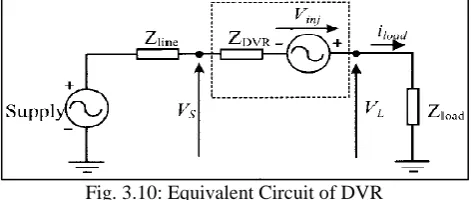
Fig. 3.10: Equivalent Circuit of DVR
DVR can be represented as a voltage source (vin j)
in series with impedance
DVR
Z , where ZDVR is the impedance
[image:1.595.311.548.609.709.2]load voltageVL. VS Represents voltage sag which is the
supply voltage to the load without compensation. Using Kirchhoff’s voltage law it can be written:
)
(
)
(
)
(
t
v
t
v
t
v
L
S
inj (2.1)Where, vL(t) is the load voltage, vS(t) is the sagged supply
voltage, vinj(t) is the voltage injected by the DVR as shown
in Fig.2.2. Under normal voltage conditions, the load power
(SL) on each phase is given by eqn. (3.2),
L L L L
L V I P jQ
S * (2.2) Where,
L
I* Is the load current, PLand QL are active and reactive power taken by the load respectively, during a sag/swell. When the DVR is active and restores the voltages back to normal, the following equation applies for each phase:
) (
)
( Sag Sag inj inj
L L
L P jQ P jQ P jQ
S (2.3)
[image:2.595.58.545.161.746.2]Where the “sag” subscript refers to the sagged supply quantities. The “inj” subscript refers to Quantities injected by the mitigation device. Generally dynamic voltage restorer is located at the point where sensitive loads are connected or regulated voltages are required as shown in Fig. 2.3.
Fig 3.11: Location of DV
IV. RESULT & DISCUSSIONS
A. Implementation of DVR
As said before DVR comprise of an inverter. Inverter exchanging ought to be controlled such that yield of the inverter tracks the reference remunerating voltage. Sine triangular PWM and Hysteresis voltage control can be utilized to produce heartbeats to the switches of three stage inverter. The three stage inverter is associated in arrangement with the transmission line with the assistance of arrangement transformer. Finish model of DVR utilizing sine-triangular PWM system for inverter6circuit is given in Fig.4.1. Different framework parameters considered for reenactment are given in Table.4.1
Parameter Valve
Source voltage V L-L 415V
DC Bus Voltage 400V
Filter Capacitance 26 µF Load Resistance 31.84 Ω Load Inductance 0.139H Table 4.1: System parameters
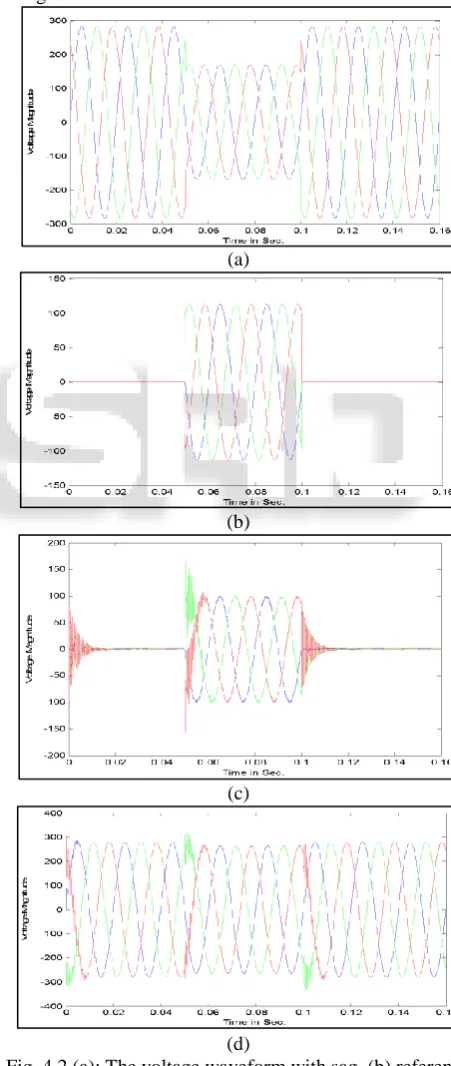
Case1. (a) Voltage sag compensation using sine triangular PWM
An adjusted voltage drop of greatness 50% of ostensible voltage happens from t=0.05 sec to t=0.10 sec. The voltage waveforms of source voltage, reference repaying voltage, and DVR inverter infused voltage and load voltage after pay are appeared in Fig. 4.10 (a), (b), (c), (d) separately. An arrangement transformer of 1:1 proportion is utilized for reproduction. It is seen from the waveform that the real infused voltage is same as the reference repaying voltage. A capacitor is associated at the yield of the inverter for the sifting reason.
(a)
(b)
(c)
(d)
[image:2.595.309.535.203.737.2]Fig. 4.2 (d) shows that voltage at load terminal is at its pre sag value all the time.
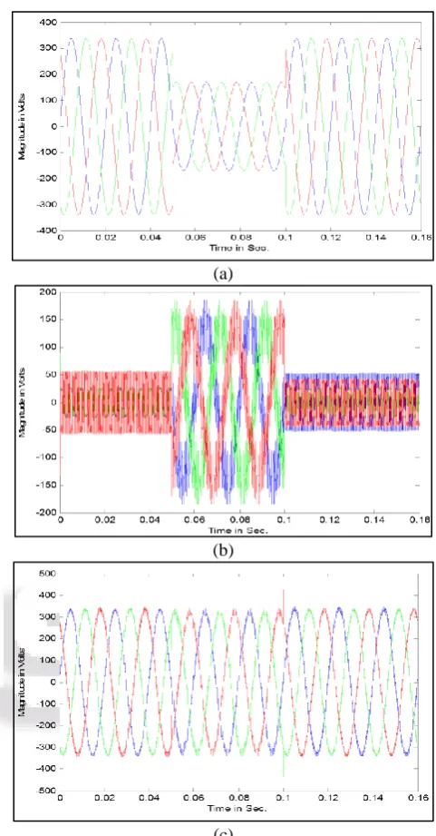
1) Case 1. (a) Voltage swell compensation using sine triangular PWM
The advantage of d-q-0 theory is that it is also applicable to compensation under voltage swell. Voltage swell of 20% can be consider for the simulation. The voltage waveform with swell, DVR injected voltage and load voltage after compensation are shown inFig.4.3 (a), (b), (c) respectively.
(a)
(b)
(c)
Fig. 4.3 (a): The voltage waveform with swell (b) DVR injected voltage and (c) load voltage after compensation using sine triangular PWM. It is clear from waveform of Fig. 4.3 (c) that voltage at sensitive load is at desired value
all the time.
2) Case 1. (b) Voltage sag compensation using hysteresis voltage control
Usage of DVR utilizing hysteresis voltage control is confirmed for a similar circuit utilizing MATLAB. An adjusted voltage drop of half extent happens from t=0.05sec to t=0.10 sec. The Fig. 4.12 (a), (b), (c) demonstrates the waveform of source voltage, DVR inverter infused voltage and load voltage after pay separately.
(a)
(b)
(c)
Fig. 4.4 (a): The voltage waveform with sag (b) DVR injected voltage and (c) load voltage after compensation
using hysteresis voltage control
3) Case1. (b) Voltage swell compensation using hysteresis voltage control
Implementation of DVR using hysteresis voltage control for swell is verified for the same circuit using MATLAB. The waveform with swell, DVR injected voltage and load voltage after compensation for voltage swell using hysteresis control are shown in Fig.4.5 (a), (b), (c) respectively.
[image:3.595.305.546.62.523.2] [image:3.595.52.286.173.602.2] [image:3.595.313.548.647.746.2](b)
(c)
Fig. 4.5 (a): The voltage waveform with swell (b) DVR injected voltage and (c) load voltage after compensation
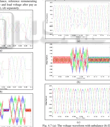
using hysteresis control 4) Case 2. Unbalance Voltage Compensation
Reenactment is improved the situation the unbalance voltage pay by utilizing hysteresis voltage control method. The voltage waveform with unbalance, reference remunerating voltage, DVR infused voltage and load voltage after pay as appeared in Fig.4.6 (a), (b), (c), (d) separately.
(a)
(b)
(c)
(d)
Fig. 4.6 (a): The voltage waveform with unbalance (b) reference compensating voltage (c) DVR injected voltage
and (d) load voltage after compensation for unbalance voltage.
5) Case 3. Non-Sinusoidal voltage sag compensation Simulation is done for the non-sinusoidal voltage sag compensation by using hysteresis voltage control technique. The voltage waveform with harmonics, DVR injected voltage and load voltage after compensation as shown in Fig. 4.15 (a), (b), (c) respectively.
(a)
(b)
(c)
Fig. 4.7 (a): The voltage waveform with unbalance (b) DVR injected voltage and (c) load voltage after compensation for
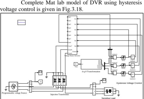
[image:4.595.47.289.62.244.2] [image:4.595.314.545.64.202.2] [image:4.595.165.534.318.743.2]Complete Mat lab model of DVR using hysteresis voltage control is given in Fig.3.18.
Fig. 3.16: MATLAB Model for Implementation of DVR using Hysteresis Voltage Control
V. CONCLUSION
DVR is an extremely successful custom power gadget for Compensating power unsettling influences, for example, voltage droop, voltage swell, lopsided voltage hang, and voltage list with music. The effect of these unsettling influences is serious on the power framework, and it makes disturbances the heap.
As conclusion Dynamic voltage restorers (DVR) can be utilized to shield touchy hardware from the power quality aggravations as said in this venture. In all cases it is required for the DVR control framework to identify begin and end of a voltage hang and voltage swell and furthermore to decide the profundity or ascent of voltage droop or voltage swell separately. The DVR, which is set in arrangement between supply framework and delicate load must have dynamic reaction against the aggravations.
REFERENCES
[1] Roger C. Dugan, Mark F. McGranaghan, Surya Santoso, H. Wayne Beaty, “Electrical Power Systems Quality”, Chapter 1 & 2 pp. 1-30, Second Edition, Tata McGraw-Hill, 2004.
[2] M. H. J Bollen, Understanding Power Quality Problems, Voltage Sags and Interruption, Piscataway, NJ: IEEE Press, 1999.
[3] S. W. Middlekauff, and E. R. Collins, “System and customer impact: consideration of series custom power devices,” IEEE Trans. on Power Delivery, vol. 13, no.1, pp.278-282, Jan. 1998.
[4] S.S. Choi, J. D. Li and D.M. Vilathgamuwa, “A generalized voltage compensation strategy for mitigating the impacts of voltage sags/swells,” IEEE Trans. on Power Delivery, vol. 20, no.3, pp.2289-2297, July 2005. [5] IEEE Standards Board (1995), “IEEE Std. 1159-1995”, IEEE Recommended Practice for Monitoring Electric Power Quality”. IEEE Inc. New York.
[6] Dr ir Marcel Didden Laboreles;Voltage Disturbances, consideration for choosing the appropriate sag mitigation device[LPQI April 2005]
[7] Ian K.P.Ross, MIEE, Omniveter Inc., Voltage sags: An Explanation- Causes, Effects and Correction-Part-1
[8] John Godsk Nielsen, Michael Newman, Member, IEEE, Hans Nielsen, and Frede Blaabjerg, Fellow, IEEE “Control and Testing of a Dynamic Voltage Restorer
(DVR) at Medium Voltage Level” IEEE
TRANSACTIONS ON POWER ELECTRONICS, VOL. 19, NO. 3, MAY 2004
[9] Hingorani N, Gyugyi L, Understanding FACTS, Wiley IEEE Press, ISBN 0-7803-3455-8, 1999.
[10]Paisan Boonchiam and Nadarajah Mithulananthan, “Understanding of Dynamic Voltage Restorers Through MATLAB Simulation” Thammasat Int. J. Sc. Tech., Vol. 11,No. 3, July-September 2006
[11]H. Ezoji, A. Sheikholeslami, M. Tabasi, M.M. Saeednia , “Simulation of Dynamic Voltage Restorer Using Hysteresis Voltage Control”. ,European Journal of Scientific Research, ISSN 1450-216X Vol.27 No.1 (2009), pp.152-166 ,© EuroJournals Publishing, K. Chan, A. Kara, and D. Westermann, "Integrated gate commutated thyristor based voltage restorer," in 1998 International Conference on Power System Technology, Beijing, China, 1998, pp. 635-638
[12]N. G. Hingorani, "Power Electronics Applications In Energy Systems," in NSF Faculty Workshop on Teaching of Courses in Power Electronics and Electric Drives, Tempe, Arizona,
[13]R. McHattie, "Dynamic Voltage Restorer the Customers's Perspective," in IEE Half Day Colloquium on Dynamic Voltage Restorer - Replacing Those Missing Cycles, 1998, pp. 1/1-
[14]S. Chen, G. Joos, L. Lopes, and W. Guo, "A nonlinear control method of dynamic voltage Restorers," in 2002 IEEE 33rd Annual Power Electronics Specialists Conference, 2002, pp.
[15]R. Buxton, "Protection from voltage dips with the dynamic voltage restorer," in IEE Half Day Colloquium on Dynamic Voltage Restorers - Replacing Those Injection Transformer
Hysteresis Voltage Crontrol
Sensitive Load
Programmable voltage Source
d-q-0 Transformation Continuous In1 Out1 Out2 Out3 Out4 Conn1 Conn2 Conn3 In1 In2 In3 In4 In5 In6 Out1 Out2 Out3 Out4 Out5 Out6 Out7 Out8 Conn5 Conn7 Conn8 Conn9 Voltage Source Inverter
A
1
+ A1 B1+ B1 C1+ C1
A
2
+
A2 B2+