Integration of Morphological Segmentation and Canny
Edge Detection for Iris Recognition
K. Lakshmi Priya
Research scholar,
Department of Computer Science, V.H.N.S.N. College, Virudhunagar – 626001,
Tamilnadu, India.
D. Christopher Durairaj
, Ph.D Associate Professor, Department of Computer Science,V.H.N.S.N. College, Virudhunagar – 626001,
Tamilnadu,India.
ABSTRACT
A new approach to iris recognition system is proposed in this paper. The iris images are captured using digital camera. The edges of the eye image are traced using canny edge detection. Segmentation is done to find the inner and outer edge of the iris region. Segmentation is done by selecting appropriate threshold approximately in the range 60 to 80 and applying Extended Minima transform. Binary code representation via phase of Daubechies wavelet is computed from each iris image and a minimum Euclidean distance classifier is applied for matching process. This approach is proved to be efficient and has less error rate for iris images captured using digital camera.
General term:
Image processing, Iris recognition,Normalization.
Keywords
:
Extended Minima transform, Rubbersheet model, Daubecheis wavelet decomposition.
1. INTRODUCTION
Biometrics analyze human body characteristics, such as DNA, eye retinas and irises, finger print, voice patterns, facial patterns and hand measurements for authentication purposes. The method of identification based on biometric characteristics is preferred over traditional passwords and PIN based methods. Iris recognition has been recently given greater attention in human identification and it's becoming increasingly an active topic in research. Iris patterns are well protected from the external environment and cannot be stolen, copied, stored or imitated.
John Daugman developed and introduced the application and usage of iris as a biometric characteristic for individual identification. He has used 2D Gabor filters and phase coding to obtain 2048 binary feature code and tested his algorithm on many images successfully [1]. The iris texture is unique from one person to other ones. Wildes proposed iris recognition, as an emerging biometric technology [2]. The motivation for this endeavour stems from the observation that the human iris provides a particularly interesting structure on which to base a technology for non-invasive biometric assessment. Since the iris is an overt body, its appearance is amenable to remote examination with the aid of a machine vision system.
A morphological theory has been developed based on iris localization algorithm[3]. Based on this concept, the objects
can be regarded as the subset in Euclidean space, and this subset can totally reflect the shape, volume, texture and grey value of the object, Therefore, morphological operation is used to identify the feature in different eye area. Huang [4] proposed a new iris recognition method based on the fusion of edge and region information consisting of three steps. The steps: 1) rough localization and normalization, 2) edge information extraction based on phase congruency, and 3) the infusion of edge and region information. Boles' prototype operates in building a one-dimensional representation of the gray level profiles of the iris [5]. He used zero-crossing of 1D wavelet transform of the resulting representation.
This paper presents an iris based personal identification system. The proposed system converts the captured iris image into a grayscale image, and, edge of the eyes is traced using Canny edge detection technique. The segmentation of the iris region is done to extract the iris region of the eye image. The radius and the pupil centre are computed. These values are used in the normalization process. Then normalization is done using Daugmans rubber sheet model [11]. The feature is then extracted using Daubechies2 wavelet [12], and matching is done using Euclidean distance [15]. The section 2 of this paper elaborates these processes in detail, section 3 presents the details of design and implementation of the recognition system and section 4 shows the results and discussion. The importance of this system is given in conclusion section.
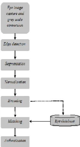
2. METHODOLOGY
Fig 1: The six phases of the iris recognition system.
2.1 Grayscale conversion
The first phase of the iris recognition system is to convert the captured eye image into grayscale to make the process simple. A novel iris recognition system using morphological edge detector and wavelet phase features [6] was proposed in 2005. The system performs grayscale conversion of image using morphological operation. Another algorithm preserves the salient features of the color image such as contrasts, sharpness, shadow, and image structure [7].
In the proposed system, gray-scale images with 256 × 256 size are collected and stored in WAMP eye database. A simple technique is used in order to eliminate artifacts on the eye image due to environmental light. The strategy is to evaluate complement of the image that is the absolute subtraction of each pixel’s intensity from 255. Then, the holes are filled in the intensity image. The area of dark pixels surrounded by lighter pixels is filled. To obtain the required gray-scale image, complement of the image is again computed.
2.2 Edge detection
The second phase of the iris recognition system is tracing the edges of the eye to make the segmentation process efficient. The proposed system uses Canny Edge Detection algorithm to find the edge of the given person’s eye. Canny [10] in 1986 proposed an edge detection algorithm. This optimal detector has a simple approximate implementation in which edges are marked at maxima in gradient magnitude of a Gaussian-smoothed image.
The raw image is convolved with a Gaussian filter to remove noise in the image due to lighting effects produced during capture process. The result is a slightly blurred version of the original which is not affected by a single noisy pixel to any significant degree. The next step is finding the gradient of the image. Edge gradient, (G) and direction, ( is determined from Eqn. (1) and Eqn. (2).
Edge gradient, (1)
Direction, (2)
As a result of non-maximum supression, a set of edge points in the form of a binary image, is obtained. Finally edge is traced. Two thresholds are chosen to trace the edges. Applying a high threshold value of thresh H, the system marks out the genuine edges. Starting from these, using the directional information derived from Eqn. 2, edges can be traced throughout the image. Applying the lower threshold value thres L,traces the faint sections of edges.
2.3 Iris segmentation
Segmenting the iris region is the third phase of the iris recognition system. The iris segmented from other parts of the eye. The inner and outer boundary of the iris region is detected to segment the iris region. Jinyu Zuo [8] in 2008 gave a new method for iris segmentation. The method integrates quality evaluation ideas directly into the segmentation algorithm. By cutting out all the bad areas, the fraction of the iris that remains can be used as a comprehensive quality measure. It also impacts system accuracy. High FAR or FRR values may come directly from bad or wrong segmentations.
Inner edge of iris can be obtained by selecting two appropriate numbers that are indicated to two upper and lower thresholds (L, U). The intensity of each pixel is converted to 0 if the intensity is lower than L+K, convert it to 255 if the intensity is bigger than U – K. Otherwise the intensity is filtered to lower one by scaling factor. The process is iterated and the inner boundary is located.
Morphological operator, Extended Minima (EM) transform is used to detect outer boundary of the iris region [3]. EM transform is the regional minima of the H-minima transform. H-Minima transform suppresses all minima in the intensity image whose depth is less than a scalar. By choosing an appropriate scalar in EM transform, a perfect edge of outer boundary is gotten.
A robust algorithm for pupil centre detection [9] using radial symmetry transform was proposed by Bei Yan. This proposed system uses the following technique to compute coordinates and radiuses of the segmented iris images. The morphological operations, clean operation removes the isolated pixels, spur operation is used to remove spur pixels, fill operation fills isolated interior pixels, are applied to the binary image. Label the connected components of image. The image's labelled pixels that are equal to i are found as a result. Then, the size of the connected components is computed. The process is repeated for n times to locate circles among the components. The pupil centre is marked and radii found.
2.4 Iris normalization
normalization process. The r emapping o f the iri s region fro m (x, y) C art esi an coordinates to the nor malized non-concentric polar r epr esentation is model led as in Eqn. 3 and Eqn 4.
(3)
[image:3.595.41.248.124.262.2](4)
Fig 2: Mapping Cartesian to polar coordinates.
2.5 Iris feature extraction
The fifth phase of the proposed iris recognition system is feature extraction. An iris image is represented as a binary feature vector. Db2 wavelet is used four times to the unwrapped iris and feature vector is computed. A general family of compactly-supported, orthonormal wavelet known as Daubechies wavelet for feature extraction is implemented [12, 13]. In particular, the four-coefficient Daubechies wavelet transform has excellent spatial and spectral locality, properties which makes it efficient for feature extraction process. Fig. 3 shows example decomposition levels. A 4-level wavelet decomposition and approximation coefficients of unwrapped iris image are obtained in the present work. Since our unwrapped image has a size of 512 × 56 pixels, after 4 times decomposition, the size of last part is 6 × 34.Feature vector is arranged by combining 408(408 = 6 × 68).
Fig 3: Daubechies decomposition.
2.6 Matching
Moi, S.H., Peng-Fei Zhang [15, 16] proposed iris recognition system that used Euclidean distance measure as the matching metric. To reduce the computational cost and improve the classification accuracy, matching is performed based on Euclidean Distance as in Eqn. 5 between input feature vector and feature vectors in database.
(5)
where N = 408, CodeA is the feature vector of the inputted iris image and CodeB is the feature vector of the iris image from the iris database. The input image's code is compared with the all other iris codes that are stored in the database.
3. SYSTEM IMPLEMENTATION
The proposed iris recognition system is implemented using ImageJ software. ImageJ is a public domain, Java-based image processing program developed at the National Institutes of Health (NIH). ImageJ was designed with an open architecture that provides extensibility via Java plugins. Custom acquisition, analysis and processing plugins can be developed using ImageJ's built-in editor and a Java compiler. User-written plugins make it possible to solve many image processing and analysis problems. ImageJ's plugin architecture and built-in development environment have made it a popular platform for image processing. ImageJ can be run as an online applet, a downloadable application. ImageJ can calculate area and pixel value statistics of user-defined selections and intensity thresholded objects. It can measure distances and angles. It supports standard image processing functions such as logical and arithmetical operations between images, contrast manipulation, convolution, Fourier analysis, sharpening, smoothing, edge detection and median filtering.
The present work is designed and developed in java. The system is then added to the plugins menu of the ImageJ software. Plugins are implemented as Java classes, which mean that all features of the Java language, access the full ImageJ API and use all standard and third-party Java APIs in a plugin. The most common uses of plugins are filters performing some analysis or processing on an image and I/O plugins for reading/writing.
The iris database is created by capturing eye images using the source, digital camera. The total number of iris present in the database is 100. The images are preserved in .jpeg format. The database is accessed using WAMP (Windows, Apache, MySQL, PHP/Perl/Python) Server. WAMPs are packages of independently created programsinstalled on computers that use a Microsoft Windows operating system. WAMP is a form of mini-server that can run on almost any Windows Operating System. The database is manipulated using MySQL. MySQL is an open-source database. The eye images are stored and retrieved from WAMP server using MySql, during this project work.
[image:3.595.110.227.471.566.2]Fig 4: GUI of iris recognition system.
The iris recognition system first involves capturing of the eye image. An eye image of a person is captured using the source, digital camera, where a color image of the eye is obtained in the jpeg format. An eye image is loaded into the memory using the action menu, the open dialogue box appears, and the captured eye image is chosen. The image is loaded (Fig. 5) into the GUI of the system and displayed in the first panel of the iris recognition system.
[image:4.595.321.521.300.368.2]
Fig 5: Eye image loaded into the system
The image is then converted to grayscale image for easy processing using morphological fill operation and is displayed in the second panel of the iris recognition window. Edges of the eye image are traced using Canny Edge Detection algorithm. The traced edges are displayed in third panel with the caption step 3. The iris region is then segmented from the rest of the eye image. Inner and outer boundaries are detected by setting threshold values and External Minima transform operation. Radius is computed and the pupil centre is marked. The inner boundary of the iris is detected and displayed in 4th panel of the system. Outer boundary is displayed in the next panel of the iris recognition system. 7th panel shows the result of segmentation process. The detected boundaries are imposed in the original eye image. The iris region is unwrapped into rectangular area using Daugmans rubber sheet model and this normalization process is displayed in the last panel of the system.
From action menu, match the eye action is chosen. The system creates a binary vector for the currently loaded image. This binary vector is compared with all the other binary vectors of the eye images present in the database. ED is the matching metric used for the iris code comparison. When a match is found, the person is authenticated and a message dialogue box appears that the person is authenticated. If there is no match found, the system rejects the person as unauthenticated and a dialog box is displayed to show the person is not authenticated.
4. RESULTS AND DISCUSSION
The eye of a person is captured using a digital camera, and is inputted into the iris recognition system. The eye image is loaded into the system. Then, the eye image (Fig. 7(a)) is converted into gray-scale image as shown in Fig. 7(b) for making the process simple. The complement of the color eye image is taken. The lighter spot that surrounding the dark spot are filled using hole filling method. The process is shown in Fig. 6.
Fig 6: Complement of the image and hole filling.
Then the complement of the image is taken again to get the gray scale image.
Fig 7(a): Original image
Fig 7(b): grayscale image
[image:4.595.342.502.438.619.2] [image:4.595.88.243.462.548.2]
Fig 8: Traced edges
Segmentation Phase of the iris recognition system is performed to segment only the iris region from other part of the eye. To get the iris region, two boundaries, inner and outer boundaries are defined. The segmented region inside the inner and outer boundary is the required iris region.
To find the inner region two thresholds are chosen. The intensity of the pixel is either converted to 0 or converted to 255, according to the threshold chosen and the iteration number. The inner boundary is traced (Fig. 9).
Fig 9: Inner boundary detected
The outer boundary (Fig. 10) is found using the EM transform method that suppresses all the minima with intensity less than a scalar value. Performing XOR centre is computed and marked. The radius for the loaded image is calculated as 0.3.
Fig 10: Outer boundary detected.
Inner boundary and outer boundary of the iris is detected and marked The Result of the process of segmentation is shown in Fig. 11.
Fig 11: Result of segmentation.
After segmenting the iris region, the iris region is unwrapped into an rectangular area of fixed size, Fig. 12 shows the process of normalization. Here Cartesian coordinate is transformed into non-concentric polor coordinate using Daugmans rubber sheet model.
Fig 12: Unwrapped iris region.
All the phases of the system are implemented. The iris operation the whole iris edge is obtained. The pupil recognition system is shown in Fig. 13.
Fig 13: Proposed iris recognition system.
The binary code (Fig. 14) is generated for matching purpose. Daubechies 2 wavelet decomposition is used 4 times to the image, and the features are extracted. The binary code for the unwrapped iris image having the values 0’s and 1’s is obtained.
Fig 14: Binary feature vector.
Performance measure is calculated for every biometric device, to compute the accuracy of the proposed system. In order to determine the accuracy of the biometric system, error rates are measured. There are two key error rates in biometrics FAR (False Acceptance Rate FAR) and FRR (False Rejection Rate). FAR is the measurement of how many imposter users are falsely accepted into the system as genuine users. FAR is given by,
FRR is the measurement of how many genuine users are falsely rejected by the system as imposter users. FRR is given by,
From the calculated FAR and FRR, The Average Efficiency of our proposed iris recognition system is computed. Table 1 illustrates the efficiency of the system. The Average efficiency can be calculated from FAR and FRR using,
AE = 100 – (FAR+FRR).
Table 1. Calculation of error rates
No. of images
No. correctly
detected
Faulty Average
Efficiency
100 92 8 98.4%
The total number of iris present in the database is 100. Out of these, 92 iris images are properly segmented and normalized. Eight images are not clearly segmented and they are proved to be faulty. The average efficiency of the system shows how much accurate and efficient the proposed iris recognition system is. The proposed system has the average efficiency of 98.4%.
5. CONCLUSION
In this paper, an algorithm that integrates canny edge detection process and morphological EM transform for iris segmentation is proposed. Canny edge detection effectively detects the edge of iris. Daubechies2 wavelet transform of iris patterns is used for feature extraction and binary vector is generated for each individual. Binary coding in feature extraction stage also caused the matching process more quickly and easily. Experimental results show that the approach has good recognition performance. In future, it would be necessary to experiment on a larger iris database in various environments to make the system more reliable. The proposed system has the average efficiency of 98.4%, which proves our system to be effective with less error rates.
6. ACKNOWLEDGEMENT
I would like to thank my parents for their endless love and support. I would like to thank Dr. Christopher Durairaj as well for his assistance and guidance with this paper.
7. REFERENCES
[1] J.Daugman 2002 How Iris Recognition works, proceedings of 2002 International conference on Image processing, vol.1, 2002.
[2] Wildes R.P. 1997 Iris Recognition: An Emerging Biometric Technology, Proceedings of the IEEE, 85(9), l348-1363.
[3] A. Poursaberi, B.N. Araabi 2004 A Fast Morphological Algorithm for Iris Detection in Eye images, 6th
International Conference on Intelligent Systems, Kerman, Iran.
[4] J. Huang, Y. Wang, T. Tan, and J. Cui 2004 A New Iris Segmentation Method for Recognition, Proc. of 17th Int'Conf. on Pattern Recognition (ICPR'04), vol. 3.
[5] Boles W., Boashah B. 1998 A Human Identification Technique Using Images of the Iris and Wavelet Transform, IEEE Trans on Signal Processing, Vol.46, 1185-1188, 1998.
[6] Poursaberi, A., and Araabi B. N. 2005 “A Novel Iris Recognition System using Morphological Edge Detector and Wavelet Phase Features”. ICGST International Journal on Graphics, Vision and Image Processing, 5(6), 262-267.
[7] Saravanan, C. 2010 Color Image to Grayscale Image Conversion,IEEE Trans, on Computer Engineering and Applications (ICCEA), Second International Conference, Vol. 2,196 – 199.
[8] Jinyu Zuo 2008 A new approach for iris segmentation, IEEE Trans, Computer society conference on Computer Vision and Pattern Recognition Workshops,1-6.
[9] Bei Yan, A robust algorithm for pupil center detection, IEEE Conference on Industrial Electronics and Applications,413-417.
[10] J. Canny 1986 A Computational Approach to Edge Detection IEEE Trans of Pattern Analysis and Machine Intelligence, vol. PAMI-8, no. 6, pages 679-698.
[11]Joshi, N.P. , Lamba, R.K. , Shah, D.U. and Ghadia, B.V. 2011 Implementation of various approaches for iris image normalization, IEEE Trans, conference on Engineering, Nirma University International , 1-5.
[12] Conjeti, S. 2012 Patient identification using high-confidence wavelet based Iris Pattern recognition, on Biomedical and Health Informatics,628-631.
[13]Vonesch, C. 2011 Generalized Daubechies wavelets, IEEE Trans on Acoustics, Speech, and Signal Processing, vol. 4, 593-596.
[14] Moi, S.H. 2009 Iris Bioetric Cryptography for Identity Document, IEEE Trans, on Soft Computing and Pattern Recognition, 736-741.