SIMULINK based Moving Object Detection and Blob
Counting Algorithm for Traffic Surveillance
Mayur Salve
B.E(Electronics) RAITDinesh Repale
B.E(Electronics) RAITSanket Shingate
B.E(Electronics) RAITDivya Shah
Asst. Professor RAITABSTRACT
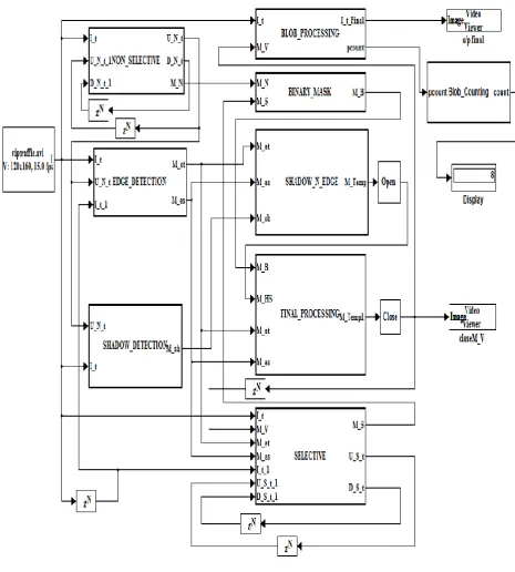
The main objective of this paper is to propose a SIMULINK MODEL to detect moving vehicles. Background subtraction is the technique used in this algorithm. Based on the retrieved information, automatic traffic surveillance can be done. Initially, a recorded video is given directly to the blocks. The main logic is then implemented using various Embedded MATLAB blocks using individual algorithms. The algorithm takes into consideration three main techniques namely Background Subtraction, Edge Detection and Shadow Detection. Background Subtraction block is sub-divided into Selective and Non-selective parts to improve the sensitivity and give accurate background. Edge detection helps to detect the exact boundaries of moving vehicles. This is followed by the shadow detection block that removes the falsely detected pixels that are generated due to shadow of the vehicle. By analyzing the output of the blocks discussed above, the final mask is generated. The mask along with the input frame processed to give the final video output with the detected object. Furthermore, using a Blob analysis block, parameters such as number of blobs per frame (vehicles) and the area of blobs can be used directly for traffic surveillance. Finally a Blob counting block is used to count and display the total number of cars.
Keywords
SIMULINK, MATLAB, Moving Object Detection, Blob Counting Algorithm, Traffic Surveillance.
1. INTRODUCTION
Complex traffic surveillance systems are often used for controlling traffic and detecting unusual situations, such as traffic congestion or accidents. This paper describes an approach which detects moving and recently stopped vehicles using the novel technique of background subtraction [1] [2]. Only the SIMULINK Utility of MATLAB Software is used to realize image processing operations. The result of the algorithm is a binary mask image of blobs representing the detected objects. The background is updated slowly with Selective and Non-selective algorithm. The use of two updating blocks improves the sensitivity of the algorithm.
1.1. About MATLAB
MATLAB is software used to compute numerical functions. All the work related to image processing is first done using
MATLAB. Image processing is any form of signal processing for which the input is a digital image, such as a photograph or video frame. The output of image processing may be either an image or parameters related to the image. Unlike other software MATLAB does pixel by pixel calculation of the input image as per the algorithm. As image sizes grow larger, software becomes less useful in the video processing realm.
1.2.About SIMULINK
SIMULINK [8] is a utility of MATLAB [8] used to represent a process in the form of blocks. A block diagram is a representation of the process consisting of inputs, the system and its outputs. Rather than writing codes as done for MATLAB, blocks are simply placed and connected to make the complete system. In short it provides a graphical user interface (GUI) for building blocks, performing simulations and finally analyzing results. In this paper, SIMULINK is used for performing Image Processing operations and to obtain appropriate results. Also, a VHDL code of SIMULINK model can be generated using the HDL Encoder tool. This code can be used to program FPGA, ASIC or other equivalent ICs.
1.3.Algorithm
Each pixel is modified independently using the statistical procedure of Gaussian distribution [3] and the pixels of the moving object is detected using the inequality mentioned below:
𝐼𝑡− 𝜇𝑡 < 𝑘 ∙ 𝜎𝑡 (1)
Where µt and σt are mean and standard deviation matrices of Gaussian distribution for image pixel intensities and constant k typically has a value between 2 and 3.The updating background image is calculated as shown by the following equations:
𝜇𝑡 𝑥, 𝑦 = 𝛼 ∙ 𝐼𝑡−1 𝑥, 𝑦 + (1 − 𝛼) ∙ 𝜇𝑡−1(𝑥, 𝑦) (2)
𝜎𝑡2 𝑥, 𝑦 = 𝛼[𝐼𝑡−1 𝑥, 𝑦 − 𝜇𝑡−1(𝑥, 𝑦)]2+ 1 − 𝛼 ∙
𝜎𝑡−12 (𝑥, 𝑦) (3)
2.
Main Block
3.
NON-SELECTIVE BLOCK
The task of detecting the moving and recently stopped vehicles is done by the non-selective block. The equation for non-selective background updating [2] [4] is given by
𝜇𝑁,𝑡 𝑥, 𝑦 =
𝜇𝑁,𝑡−1 𝑥, 𝑦 + 𝛿𝑁1 if 𝐼𝑡 𝑥, 𝑦 > 𝜇𝑁,𝑡−1 𝑥, 𝑦
𝜇𝑁,𝑡−1 𝑥, 𝑦 − 𝛿𝑁1 if 𝐼𝑡 𝑥, 𝑦 > 𝜇𝑁,𝑡−1 𝑥, 𝑦
𝜇𝑁,𝑡−1 𝑥, 𝑦 otherwise
(4)
Where It (x y) is the brightness of a pixel situated at coordinates (x,y) of input monochrome image at the time t; µN, t (x,y) the brightness of a pixel situated at coordinates (x,y) of background image, updated non-selectively;
δN1 = 2-5 = 0.03125 is a small constant evaluated experimentally. It is assumed that the brightness of the input image is in the range: It(x,y) <0,255>. The updating of
which is
from (1) for non-selective model [2] is given by (5):𝜎𝑁,𝑡 𝑥, 𝑦 =
𝜎𝑁,𝑡−1 𝑥, 𝑦 + 𝛿𝑁1 if |𝐼𝑡− 𝜇𝑁,𝑡−1| > 𝜎𝑁,𝑡−1
𝜎𝑁,𝑡−1 𝑥, 𝑦 − 𝛿𝑁1 if |𝐼𝑡− 𝜇𝑁,𝑡−1| < 𝜎𝑁,𝑡−1
𝜎𝑁,𝑡−1 𝑥, 𝑦 otherwise
(5)
[image:3.595.317.507.277.415.2]where
is experimentally evaluated to be 0.00390625 (i.e. 2-8). The values of µN,t and
are used to calculate the pixel values of mN from equation (1).Figure 2: Showing It (x,y) and mN (x,y)
respectively.
4.
SELECTIVE BLOCK
This block is similar to the non-selective block, but it depends on the final mask output [4] as shown by (6):
𝜇𝑆,𝑡 𝑥, 𝑦 =
𝜇𝑆,𝑡−1 𝑥, 𝑦 + 𝛿𝑆1 if 𝐼𝑡−1 𝑥, 𝑦 > 𝜇𝑆,𝑡−1 𝑥, 𝑦
and 𝑚𝑉𝑇𝑆,𝑡−1 𝑥, 𝑦 = 0
𝜎𝑆,𝑡−1 𝑥, 𝑦 − 𝛿𝑆1 if 𝐼𝑡−1 𝑥, 𝑦 > 𝜇𝑆,𝑡−1 𝑥, 𝑦
and 𝑚𝑉𝑇𝑆,𝑡−1 𝑥, 𝑦 = 0
𝜎𝑆,𝑡−1 𝑥, 𝑦 otherwise
(6)
𝜎𝑆,𝑡 𝑥, 𝑦 =
𝜎𝑆,𝑡−1 𝑥, 𝑦 + 𝛿𝑆2 if |𝐼𝑡−1 𝑥, 𝑦 − 𝜇𝑆,𝑡−1 𝑥, 𝑦 |
>𝜎𝑆,𝑡−1 𝑥, 𝑦 and 𝑚𝑉𝑇𝑆,𝑡−1 𝑥, 𝑦 = 0
𝜎𝑆,𝑡−1 𝑥, 𝑦 − 𝛿𝑆2 if |𝐼𝑡−1 𝑥, 𝑦 − 𝜇𝑆,𝑡−1 𝑥, 𝑦 |
< 𝜎𝑆,𝑡−1 𝑥, 𝑦 and 𝑚𝑉𝑇𝑆,𝑡−1 𝑥, 𝑦 = 0
𝜎𝑆,𝑡−1 𝑥, 𝑦 otherwise
(7)
where mVTS,t (x, y) = mV,t (x, y) ˅ mET,t (x, y)
mES,t (x, y) ;
S,t (x, y) – the brightness of a pixel at coordinates (x, y) of background image updated using selectivity; mV (x, y) – the element of the detected vehicle mask image of value equal to 0 or 1, where 1 denotes the detected moving objects. The values of constants
S1 and
S2 were established experimentally:
S1 = 0.25,
S2 = 0.03125 for Itx, y) 0,255>. From (1), the image frame ms comes out as shown below:Figure 3: Showing ms(x,y)
5.
BINARY
MASK
COMBINATION BLOCK
The output from both selective and non-selective block is combined into a single binary mask. A simple AND operation is not enough to detect all the pixels. Hence a special combination of AND and OR operations [5] are used to improve the detection as shown (8):
𝑚𝐵 𝑥, 𝑦 =
𝑚𝑆 𝑥, 𝑦 ∨ 𝑚𝑁 𝑥, 𝑦 if ((𝑚𝑆 𝑥 − 1, 𝑦 ∧ 𝑚𝑁 𝑥 − 1, 𝑦 )
∨ 𝑚𝑆 𝑥 − 1, 𝑦 − 1 ∧ 𝑚𝑁 𝑥 − 1, 𝑦 − 1
∨ 𝑚𝑆 𝑥, 𝑦 − 1 ∧ 𝑚𝑁 𝑥, 𝑦 − 1
∨ 𝑚𝑆 𝑥 + 1, 𝑦 − 1 ∧ 𝑚𝑁 𝑥 + 1, 𝑦 − 1
𝑚𝑆 𝑥, 𝑦 ∧ 𝑚𝑁 𝑥, 𝑦 otherwise
(8)
[image:3.595.96.276.418.556.2]6.
TEMPORAL AND SPATIAL
EDGE DETECTION
During a dark scene, True Positive pixels [2] may not be detected and a major portion or the car may be neglected. So to improve the segmentation quality, the TP pixels need to be increased. This is done by using two type of edge detection: Temporal and Spatial Edge Detection blocks.
In temporal edge detection block, the edges are detected by taking the difference of the current and previous frame:
Δ𝐼𝑇= |𝐼𝑡− 𝐼𝑡−1| (9)
In spatial edge detection, the difference of current image and background is taken as below:
Δ𝐼𝑆= |𝐼𝑡− 𝜇𝑁,𝑡| (10)
Temporal and spatial edge image mask mET and mES respectively is given by the following equation: 𝑚𝐸𝑇 𝑥, 𝑦 =
[image:4.595.331.473.138.267.2] [image:4.595.126.248.444.626.2] [image:4.595.326.477.457.584.2]1 if |Δ𝐼𝑇 x, y − Δ𝐼𝑇 x − 1, y | > 𝜃𝐸𝑇∨
|Δ𝐼𝑇 x, y − Δ𝐼𝑇 x, y − 1 | > 𝜃𝐸𝑇
0 otherwise
(11)
𝑚𝐸𝑆 𝑥, 𝑦 =
1 if |Δ𝐼𝑆 x, y − Δ𝐼𝑆 x − 1, y | > 𝜃𝐸𝑆∨
|Δ𝐼𝑆 x, y − Δ𝐼𝑆 x, y − 1 | > 𝜃𝐸𝑆
0 otherwise
(12)
where θET and θES are constant threshold values.
Figure 5: Showing mETand mES respectively.
7.
SHADOW DETECTION
Shadows get detected and may be misunderstood by the system to be an object itself. Hence to remove any such discrepancies, the Shadow detection technique is used. By comparing the decrease in
𝑚𝑆𝐻 𝑥, 𝑦 = 1 if 𝛼 ≤ 𝐼𝑡(𝑥,𝑦)
𝜇𝑁,𝑡(𝑥,𝑦)≤ 𝛽
0 otherwise
(13)
where α and β are constant coefficients: α=0.55, β=0.95, both evaluated experimentally.
Figure 6: Showing mSH.
8.
FINAL PROCESSING
The masks obtained by implementing the previous algorithms are combined into a single mask M_Temp1:
𝑚𝐻𝑆= 𝑑𝑖𝑙(𝑒𝑟𝑜(~(𝑚𝐸𝑇∧ 𝑚𝐸𝑆) ∧)𝑚𝑆𝐻) (14)
𝑀𝑇𝑒𝑚𝑝 1= 𝑒𝑟𝑜(𝑑𝑖𝑙 𝑚𝐵∧ ~𝑚𝐻𝑆 ∨ 𝑚𝐸𝑇∧
𝑚𝐸𝑆 ) (15)
where dil() and ero() denote 2x2 morphological dilation and erosion operation [2] respectively. The mask thus obtained usually contains False negative and False positive pixels. Hence to improve the shape of the blobs, the inbuilt opening block is added to obtain the final frame of mask mV.
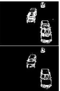
Figure 7: Showing mV.
9.
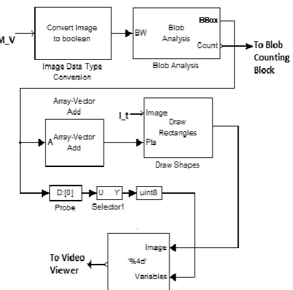
BLOB PROCESSING
Figure 9: Image showing the detected objects.
10.
BLOB COUNTING BLOCK
The Blob Processing block helps to find the number of vehicles visible per frame. But this number might not be particularly helpful for traffic surveillance. So an additional Embedded MATLAB function block is added to count the total number of cars that are passing. The result is displayed using the inbuilt display block as shown in figure 1.
11.
CONCLUSION
The system realizes real-time motion segmentation and morphological operations. The important advantage of using SIMULINK is that a complete design of the system can be generated, visualized and analyzed as required. Also, a VHDL code of SIMULINK model can be generated using the HDL Encoder tool provided in SIMULINK. This code can be used to program FPGA, ASIC or other equivalent ICs. As a future scope, the output of the proposed algorithm can be used for automatic speed detection of vehicles and estimate direction of
motion. Number plate detection algorithm can be used along with the discussed algorithm to generate a log of the necessary information such as number plate, time of passing, speed of the vehicle, etc.
12.
ACKNOWLEDGEMENTS
We are thankful to Dr. M. D. Patil, HOD(electronics) for their support and encouragement. We also want to thank college staff and family members for their constant support.
13. REFERENCES
[1]. Sen-Ching S. Cheung and Chandrika Kamath, “Robust Background Subtraction With Foreground Validation For Urban Traffic Video” in Proc. SPIE Video Communication and Image Processing, 2004,pp.881-892. [2]. Marek Wójcikowski, Robert Zaglewski,
“FPGA-Based Real-Time Implementation of Detection Algorithm for Automatic Traffic Surveillance Sensor Network”.
[3]. A. Franois, G. Medioni, "Adaptive Color Background Modeling for Real-Time Segmentation of Video Streams", in Proc. of Int. Conf. Imaging Science, Systems and Technology, Las Vegas, NV, 1999, pp. 227-232.
[4]. F. Porikli, Y. Ivanov, T. Haga, "Robust abandoned object detection using dual foregrounds", EURASIP J. Adv. Signal Process,Jan.2008.
[5]. D. Duque, H. Santos, P. Cortez, "Moving Object Detection Unaffected by Cast Shadows,Highlights and Ghosts", in Proc. IEEE Int. Conf. Image Processing, 2005, pp. 413-416.
[6]. R. Cucchiara, C. Granna. M. Piccardi, A. Prati, S. Sirotti, "Improving Shadow Suppression in Moving Object Detection with HSV Color Information", in Proc. IEEE Intell. Transp. Syst. Conf., Oakland, CA, 2001, pp. 334-339. [7]. R. Cucchiara, C. Granna. M.Piccardi, A. Prati,
"Detecting Moving Objects, Ghosts and Shadows in Video Streams", IEEE Trans. Pattern Anal. Machine Intell., vol. 25, no. 10, pp. 1337-1342, Oct. 2003.
[image:5.595.92.266.311.403.2]