Performance of AODV, GRP and OLSR Routing
Protocols in Adhoc Network with Directional Antennas
Mandeep Singh
Department of Computer Science, Punjabi University Patiala-147001(Punjab), India
Maninder Singh
Department of Computer Science, Punjabi University Patiala-147001(Punjab), India
ABSTRACT
Wireless adhoc netwok is a decentralized type of wireless network, it does not rely on a preexisting infrastructure. These types of networks are used in situations where temporary network connectivity is needed. This research paper explores the effect of using directional antennas in ad hoc network. Antenna patterns of omni directional and directional antenna have been developed using the OPNET Modeler 14.0. Simulation scenarios have been created for both antennas with three routing protocols AODV, GRP, OLSR. From the results of the simulation, we observe that data dropped rate (Retry threshold), Load and Delay graphs in case of directional antenna network shows better performance than omni directional antenna network. Among three routing protocols which we have used in our network model, OLSR routing protocol shows better performance and high throughput for directional antennas as compare to AODV and GRP routing protocols.
Keywords
Adhoc Network, Routing protocols, Antennas, OPNet.
1. INTRODUCTION
Wireless ad hoc netwok is a decentralized type of wireless network, ‘Ad-hoc’ Latin word means ‘for this’ or for this only. The network is ad hoc because it does not rely on a preexisting infrastructure, such as routers in wired networks or access points in managed (infrastructure) wireless networks. An Ad Hoc network is multi-hop wireless network where nodes may be mobile. Each node participates in routing by forwarding data for other nodes and so the determination of which nodes forward data is made dynamically based on the network connectivity[1]. These types of networks are used in situations where temporary network connectivity is needed. Ad hoc networks are formed on a dynamic basis, i.e. a number of users may wish to exchange information and services between each other on an ad hoc basis. An example of these type of networks can be found in a disaster relief situation. Here an Ad Hoc network could enable emergency services to co-ordinate emergency services more effectively or enable medics in the field to retrieve patient history from hospital databases[2]. Some of the advantages of ad hoc networks are : Independence from central network administration, Self configuring, Self healing through continuous reconfiguration, accommodates the addition of more nodes, being able to access the Internet from many different locations. This research paper provides comparative study of directional antenna with omni-directional antenna through simulation of three routing protocols (AODV, GRP, OLSR) for mobile Ad hoc networks by using well known network simulator OPNET modeler.
1.1 Related Work
During the last few years many research papers and reports are published on various issues of mobile Ad hoc networks.
We review the current literature on protocols that are designed to use with directional antennas in adhoc networks. The work on medium access control involves using antennas intelligently for collision avoidance and spatial reuse purposes. In [3] H.K Patel et all proposed a novel, robust MANET protocols framework for tracking performance metrics and evaluating theoretical predictions. Because of specific characteristics of wireless ad hoc networks [4] such as dynamicity, heterogeneity of devices, bandwidth and energy constraints, a wireless ad hoc network management architecture presents different requirements from those for fixed networks. There is directional CSMA/CD mechanism [5], that utilizes a switched beam antenna array and assumes that the gain of the directional antenna is equal to the gain of an omni-directional antenna. For problem of detection probability estimation of omni-directional antennas and directional antennas, Xiaofeng Lu proposed a detection probability model to calculate the probability of detecting a transmitter at any location [7]. It shows that the transmitter‘s probability of being detected by detection systems cannot be reduced by the directional antennas with same transmit power. There has been some work on protocols that exploit the use of directional antenna in adhoc networks. The protocols cannot completely overcome the problem that arise due to use of such antennas and are not yet designed to completely cope with mobility. The effects of interference and multipath on MAC protocols has been analyzed F. babich et all for WLANs with nodes employing smart antennas at physical layer [6].which shows that Adaptive arrays may guarantee a higher robustness but omnidirectional antenna reception does not perform satisfactorily.
2. ROUTING PROTOCOLS IN MANET
An ad-hoc routing protocol is a convention, or standard, that controls how nodes decide which way to route packets between computing devices in a mobile ad hoc networks. In our network, we have used three routing protocols (AODV, OLSR, GRP).Each protocol is used in directional scenario as well as in omni-directional scenario. The routing protocol parameters used in network are given in the tables below:2.1 AODV
node will rebroadcast the RREQ. When a node re-broadcasts a Route Request, it sets up a reverse path pointing toward the source. This reverse path is used to forward Route Reply (RREP) unicast back to the source. Route Error (RERR) If a node is unable to forward packet, it generates a RERR message. When the originator node receives the RERR, it initiates a new route discovery for the given route.
Table 1. AODV routing protocol parameters
Serial No. Parameters Value
1. Active route timeout
30 seconds
2. Hello intervals Uniform(10,1 0,1) 3. Allowed hello
loss
20
4. Route error rate limit
10 pkts/sec
5. Timeout
Buffer
2
6. Packet queue size
Infinity
7. Addressing mode
IPv4
2.2 Optimized Link State Routing Protocol
[image:2.595.48.240.174.408.2]The Optimized Link State Routing Protocol (OLSR) for MANET is a proactive, link-state routing protocol where each node maintains topology information by periodically exchanging linkstate messages [12]. The novelty of OLSR is to employ multipoint relays (MPRs) to minimize the number of control messages flooding in the network. Each node chooses a subset of its one hop neighbors (MPRs) in such a way that these MPRs will cover all two-hop away neighbors. Hence, messages are only flooded through MPRs, and not to all nodes. Core functioning of OLSR is: Packet format and forwarding, link sensing with hello messages, neighbor detection, MPR selection and MPR signaling, topology control message diffusion, route table computation, node configuration[3].Three control messages are defined to provide this functionality. HELLO HELLO messages are exchanged between neighbors only, and diffuse information about the one-hop neighbors of a node. Upon reception of HELLO messages, the two hop neighborhood can be discovered and further the MPRs of the given node can be chosen. The MPRs chosen by a node is further marked in the following HELLO messages broadcasted by that node.TC - Topology Control in OLSR, all nodes chosen as MPR will transmit TC messages. The TC messages contain the address of the node generating the message, as well as the list of nodes that has chosen the given node as MPR (MPR selectors). TC messages are further flooded using the MPRs, disseminating network topology information to all the nodes in the OLSR network.MID - Multiple Interface Declaration, The MID message is broadcasted by nodes running OLSR on more than one network interface.
Table 2. OLSR routing protocol parameters
Serial No. Parameters Value
1. Hello Interval 2.0 seconds 2. TC Interval 5.0 seconds
3. Neighbor Hold
Time
6.0 seconds
4. Topology
Hold Time
15.0 seconds
5. Addressing
Mode
IPv4
2.3 Geographic Routing Protocol (GRP)
This schema collects network information at a source node with a small amount of control overheads. According to the collected information, source node can finds routes and continuously transmit data even if the current route is disconnected. The result of this approach is achieving fast transfer with less overhead of control massages [3]. This approach is widely known as hybrid routing protocol, because it can simultaneously use the strengths of reactive routing and proactive routing protocols. A packet that named DQ is used continuously to forward to each node’s neighbours until the destination is reached. When it reaches the destination, the destination node broadcasts a network information gathering (NIG) packet to its neighbours. The source node computes the best route according to collected information and then immediately starts to transmit data packets.
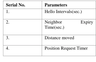
Table 3. GRP routing protocol parameters
Serial No. Parameters
1. Hello Intervals(sec.)
2. Neighbor Expiry
Time(sec.)
3. Distance moved
4. Position Request Timer
3. ANTENNA PATTERN DESIGN IN
OPNET MODELER
Antennas collect radio frequency energy from space for reception purpose and distribute energy into space for transmission.
[image:2.595.331.520.437.559.2]Fig.1. Omni-Directional antenna pattern designed by using OPNET
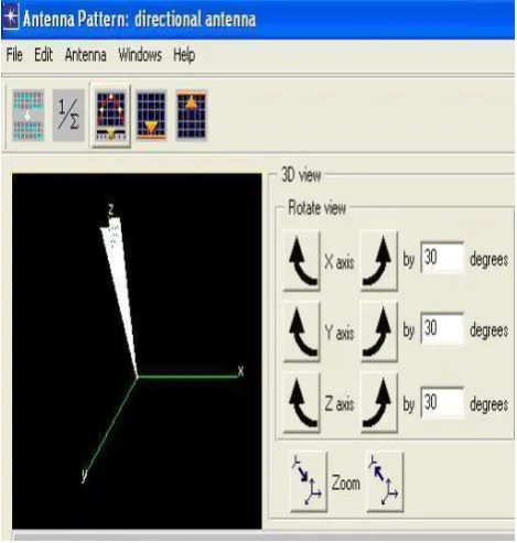
[image:3.595.317.566.221.436.2]During the antenna pattern design, firstly two antenna patterns are designed one for directional antenna and second for omni-directional antenna in “antenna pattern editor” of OPNET simulation tool. For designing both antenna pattern some mathematical and trigonometric equations are used. And then accordingly parameters are set in “Antenna pattern editor” OPNET. The antenna gain pattern specified in the Antenna Pattern Editor can be used to provide the gain values, given knowledge of the relative positions of the nodes. Calculations related to this aspect of radio link modeling are performed in the Radio Transceiver Pipeline.
Fig. 2. Directional Antenna pattern designed by using OPNET
4.
SIMULATION
SET
UP
AND
NETWORK DESIGN
The network simulation are implemented using OPNET modeler 14.0. OPNET Modeler is commercial network simulation environment for network modelling and simulation. It allows the users to design and study communication networks, devices, protocols, and applications with flexibility and scalability. It simulates the network graphically and gives the graphical structure of actual networks and network components. Creating the simulation scenario that is equivalent to the real world is the first step of simulation. The basic ad hoc network model of 40 mobile nodes has been built.
Fig.3. Ad Hoc Network model used
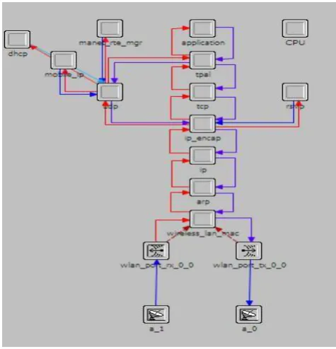
Two different mobile nodes are designed by modifying the existing wlan workstatin node in OPNET object pallet. The steps used to make this network are as follows:
Firstly two antenna patterns are designed one for directional antenna and second for omni-directional antenna in “antenna pattern editor” of OPNET simulation tool. For designing both antenna pattern some mathematical and trigonometric equations are used. And then accordingly parameters are set in “Antenna pattern editor” OPNET. The antenna gain pattern specified in the Antenna Pattern Editor can be used to provide the gain values, given knowledge of the relative positions of the nodes. Calculations related to this aspect of radio link modeling are performed in the Radio Transceiver Pipeline. Then from wireless node module provided by
OPNet object palette, “wireless station” (wlan wkstn adv) node is taken and modified according to antenna implementation requirement. After modifying “wlan_wkstn_adv” node, two new node models are designed .
On first node model we have implement omni_directional antenna and on second node model we have implement directional antenna. Two directional antenna are implemented on each node, one for transmitter and second for receiver.
[image:3.595.55.290.445.692.2]configure the applications “Profile configuration” node is used.
[image:4.595.308.544.85.370.2] We have created six scenarios by using routing protocols (AODV, OLSR, and GRP) for the performance analysis.
Fig. 4. Node model of with directional antenna
Network parameters control the interaction of nodes and devices over the network. In the Table 1 some parameters which are used in our network are given with their values.
Table 4 : Network Parameters
Serial No. Parameters Value
1. Maximum simulation time
120 seconds
2. No. of nodes 40
3. Environment size 500*500
4. Routing protocols AODV,OLSR,GRP
5. Data rate 54 Mbps
6. Trajectory Vector
7. Packet size 1024
8. Physical
characteristics
Extendedrate PHY(802.11G) 9. Antennas used
Directional,Omni-directional 10. Directional gain 12 dBi
11. Application Video conferencing
5. RESULTS AND ANALYSIS
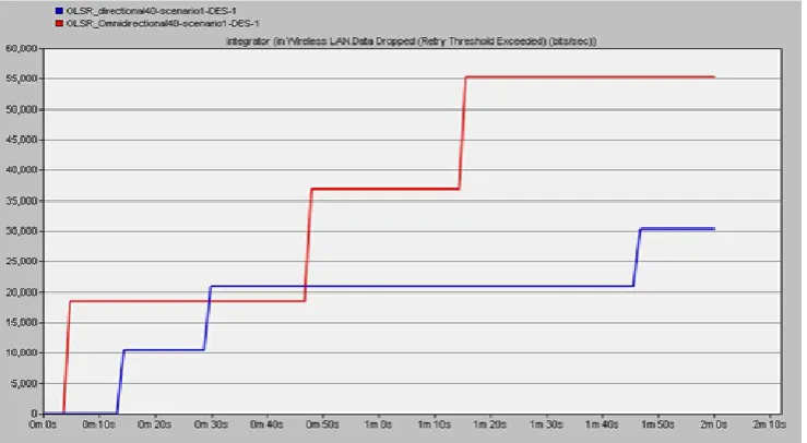
From all result graphs, It is found that scenario with directional antenna has less delay,low data dropped rate, But throughput is almost same in comparison to omni-directional antennas in all three routing protocols.Among three routing protocols that are used in network for routing OLSR shows better performance than AODV and GRP.There are four figures given to conclude the results taken by running simulation in OPNET.
[image:4.595.54.292.133.380.2]Fig. 5. Wireless LAN.Data Dropped (Retry Threshold Exceeded) in OLSR routing protocol
Wireless LAN Delay of both scenarios with OLSR routing protocol is shown in Figure 6.It is the time taken by a packet from the movement it is transmitted on the network by source node to reach the destination node. By using parameters of OLSR routing protocol given in Table No. 2 results are
[image:5.595.106.486.406.611.2]taken.It is found that scenario with directional antenna has less delay.Directional antenna directed towards direction of destination node which leads to less delay in arrival of packets from source node to destination node.
Fig. 6. Wireless LAN Delay in OLSR routing protocol
Figure 5 shows the results for WLAN Delay for both scenarios by taking GRP routing protocol. Network parmeters are given in Table No.4 and GRP protocols parameters given in Table No.3 are taken.Similarly as results of OLSR shows
Fig. 7. Wireless LAN Delay in GRP routing protocol
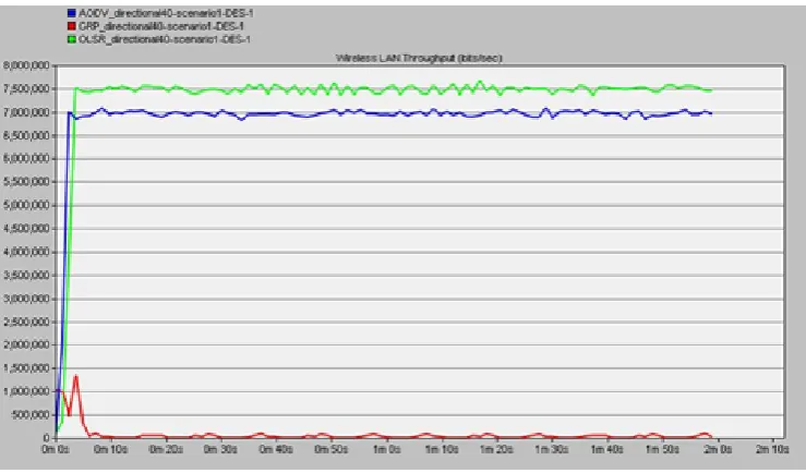
The graph shown in Figure 8 shows the results of Wireless LAN Throughput of three routing protocols in directional antenna scenario. It is the number of packets received by all the destination nodes over the duration of simulation. The results are taken by taking network parameters given in Table No.4 and Routing protocol parameters of AODV,OLSR and GRP shown in Table No.1,2 and 3 respectively.It is found that among these three routing protocols ,OLSR gives very
high throughput for directional antennas. As the Optimized Link State Routing Protocol (OLSR) for MANET is a proactive, link-state routing protocol where each node maintains topology information by periodically exchanging link state messages. The novelty of OLSR is to employ multipoint relays (MPRs) to minimize the number of control messages flooding in the network.
Fig. 8. Throughput of directional antenna network with AODV, GRP and OLSR
6. CONCLUSION
In this paper we have examined the incorporation of directional antennas into ad hoc networks. Through simulation we observed that using directional antennas provides better network performance as compared to scenarios using omnidirectional antenna. The increase in the throughput depends on the spatial location of nodes in the network. Among three routing protocols that we have used in our network scenarios, OLSR routing protocol has better performance than AODV and GRP routing protocols. As
OLSR is to employ multipoint relays (MPRs) to minimize the number of control messages flooding in the network. OLSR protocol is very effective and efficient route discovery protocol for ad hoc networks with directional antennas.
7. ACKNOWLEDGMENT
[image:6.595.114.484.407.624.2]8. REFERENCES
[1] Moharapa, P. and Krishnamurthy, S. 2005. Adhoc Network Technology and Routing Protocols. Springer. [2] Dham, V. 2003. Link Establishment in Ad Hoc Networks
using Smart Antennas. Viginia Polytechnic Institute and State University.
[3] Patel, H.K., Srivastava, R., and Dubey, P.K. 2012 Performance Analysis of Mobile Ad hoc networks. Int. J. Sci. Eng. Tech., 95-101.
[4] Ulema, M., Nogueira, J.M., and Kozbe, B. 2006 Management of Wireless Ad Hoc Networks and Wireless Sensor Networks. J. Net. Sys. Manage., 327-333. [5] Nasipuri, A., Ye, S., You, J., and R. Hiromoto, R. 2010.
A MAC Protocol for Mobile Ad Hoc Networks using Directional Antennas. Proceedings of the IEEE Wireless Communications and Networking Conference. 1214-1219, Chicago, Illinois, September 23-28.
[6] Babich, F., Comisso, M., D’orlando, D. and Mani`a, L. 2006. Interference Mitigation on WLANs Using Smart Antennas. Wireless Personal Communications, 387-401. [7] Lu, X., Fletcher, Wicker, D., Towsley D., Xiong, Z., and
Lio, P. 2010. Detection Probability Estimation of Directional Antennas and Omni-Directional Antennas. Wireless Pers Commun. 51-63.
[8] Babich, F., Comisso, M. and Mania, L., 2009. Sustainable Simultaneous Communications in Ad-hoc
Networks using Smart Antenna Systems. Wireless Network. 1074-1085.
[9] Hussain, M.A., Varma, P.S., Rajesh, K.S., Pathan, H.B. and Sarraju, L.M. 2010. Use of Smart Antennas in Ad hoc Networks. Int. J. Comput. Sci. & Inf. Tech. (IJCSIT),47-54
[10]Choudhury, R.R. and Vaidya, N.H. Deafness: A MAC Problem in Ad Hoc Network when using Directional Antennas. Proceedings of the 12th IEEE International Conference on Network Protocols (ICNP’04).
[11]Saha, A.K. and Johnson, D.B. 2003. Routing Improvement using Directional Antennas in Mobile Ad Hoc Networks. Proceedings of conference on 07/03/2003, Rice University.
[12]Tamilarasan, S. 2012. A Quantitative Study and Comparison of AODV, OLSR and TORA Routing Protocols in MANET. Int. J. Comput. Sci. 364-369. [13]Takai, M., Martin, J., Ren, A. and Bagrodia, R. 2001.
Directional Virtual Carrier Sensing for Directional Antennas in Mobile Ad Hoc Networks. The J. Mobile Communi., Comput., Inf. 297-305.