2019 International Conference on Applied Mathematics, Modeling, Simulation and Optimization (AMMSO 2019) ISBN: 978-1-60595-631-2
Effect of Truss Number on the Dynamic Response of Truss
Pei-pei YANG
1and Zhen-kai HUANG
2,*1
School of Architecture and Engineering, Chang'an University, PR China
2
School of Material Science and Engineering, Shanghai University, PR China
*Corresponding author
Keywords: Truss, Truss number, Finite element model, Dynamic response.
Abstract. The safety of truss is determined by dynamic response of truss during the engineering application. Truss number is an important parameter for the engineering application of truss, which is related with the economy and convenience. The effect of truss number on the dynamic response of truss can be analyzed by means of commercial finite element software. Here, a finite element model (FEM) was employed to simulate the dynamic response of truss structure. By using the proposed FEM, the effects of truss number on the maximum displacement and Mises stress were researched. Based on the numerical results, the dynamic responses are different from each other for different truss numbers. The maximum displacement and Mises stress increase with the increasing truss number; however, the maximum displacement and Mises stress keep on a stable value when truss number is more than a certain number.
Introduction
Truss structure is widely used in bridge, aerospace and construction because of its high ratio of stiffness to mass. Truss structure can be under dynamic loading during its usage. Maximum displacement is an important parameter during the design of truss structure. If the maximum displacement of truss structure is not satisfied with the available standard, there would be a risk during the usage of truss structure. Therefore, the effect of impact speed on the maximum displacement should be analyzed to make sure the safety of truss structure.
For uniform beam structure, there is a classical theory to calculate the mehcanical resposne [1]. The theoretical model is useful for the homogeneous beam section. For truss structure, the sections of truss are inhomogeneous; therefore, the available theory is useless to calculate the mechanical resposne of truss structure. Fortunately, it has been demonstrated that finite element model (FEM) is a valid technology to analyze mechanical properties of truss structure [2-5]. From then on, the FEMs of truss structure have been widely researched. In order to analyze the elasto-plastic small deformation, an extended multiscale finite element method was developed for 2D periodic lattice truss materials [6]. Before using FEM to predict the deformation of truss structure, the differences between matrix displacement method and finite element method were analyzed [7]. Based on the stiffness and load matrix of bridge frames, a FEM was established to calculate the lateral displacement under the loading of wind [8]. The initial yield surface of periodic 2D trusses of beams and evolution of the yield surface with ongoing hardening were both added into an asymptotic discrete expansion FEM to simulate the elastoplastic homogenized response of lattice truss structure [9]. In order to realize the geometrical nonlinear analysis of the structures with lattice truss materials, an equivalent continuum multiscale formulation was presented by combining the extended multisacle finite element method with the co-rotational approach [10]. The static resposne of truss structure has been widely investigated; however, the effect of truss number on dynamic response of truss structure has not been explored.
Finite Element Model
[image:2.595.78.500.337.581.2]The finite element model (FEM) aimed to simulate the mechanical behavior of truss structure, has been developed by means of Abaqus 6.11-1 [11,12]. In order to research the mechanical properties of truss structure, a 3D FEM has been defined accounting for the truss geometry, materials and boundary conditions. A deformable 3D truss model was generated by means of planar commands. Concerning the meshing of the beam, the truss has been discretized by means of shear-flexible elements adopting the global seeds meshing technique. In order to favor convergence and reduce the computational time, the simplest element type has been chosen, for example the B31, that is a 2-node linear beam in space. Figure 1 illustrates FEM of truss structure. The boundaries for simply supported beam was used here. The bar with the length of 400 m and the diameter of 50mm is above the truss structure. The length of truss structure is 10m and the transverse section of truss structure is 1m×1m. The spacing of the adjacent truss is 20 m. The impact speed V is about 14 m/s. In this study, the parameters of truss structure and bar are fixed. Only the number of truss is varied, e.t., 1~9. The different FEMs are shown in Table 1. The model consisted of approximately 8200 elements and 7961 nodes. A dynamic explicit procedure type was chosen to calculate the dynamic response of truss structure. When the calculations of the dynamic response have been accomplished, the Mises stress and maximum displacement of truss structure are obtained by picking up data from the output databases. Based on the calculated results, the effect of truss number on the dynamic response was analyzed.
Figure 1. Finite element model (FEM) of 3D truss structure.
Table 1. Different truss numbers for FEM.
No. of FEM 1 2 3 4 5
Number of truss 1 3 5 7 9
Dynamic Response
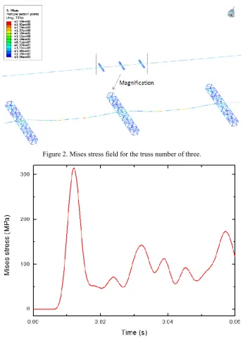
Figure 2. Mises stress field for the truss number of three.
Figure 3. Variation of Mises stress with time at the maximum response zone.
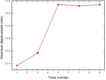
The effect of truss number on the dynamic resposne of truss structure is illustrated in Figure 4. The relationship between maximum displacement and truss number is nonlinear. The maximum displacement increases greatly with the truss number if the truss number is less than 5. The maximum displacement keeps a stable value if the truss number is more than 5. This explains that five trusses are enough to absorb the energy of impact bar. According to the simulated results in Figure 4, the maximum displacement is about 13.34 mm.
Concluding Remarks
and then keeps a stable value if truss number is more than a certain value. The certain value here is five and the stable maximum displacement is 13.34 mm.
Figure 4. Maximum displacement at different truss numbers.
Acknowledgement
This research was financially supported by Fundamental Research Funds for for undergraduates.
References
[1] F. P. Beer, E. R. Johnston, J. T. DeWolf. Mechanics of Materials, Fourth Edition. 2006. The McGraw-hill Companies, Inc. New York.
[2] J.M. Guedes, N. Kikuchi. Preprocessing and postprocessing for materials based on the homogenizationmethod with adaptive finite elementmethods. Comput. Methods Appl.Mech.Eng. 83, 143–198 (1990).
[3] J. Yan, G.D. Cheng, S.T. Liu, et al. Comparison of prediction on effective elastic property and shape optimization of truss material with periodicmicrostructure. Int. J. Mech. Sci. 48, 400–413 (2006).
[4] K. Terada, N. Kikuchi. A class of general algorithms for multiscale analyses of heterogeneous media. Comput. Methods Appl. Mech. Eng. 190, 5427–5464 (2001).
[5] C. Miehe, C.G. Bayreuther. On multiscale FE analyses of heterogeneous structures: From homogenization tomultigrid solvers. Int. J. Numer. Methods Eng. 71, 1135–1180 (2007).
[6] T.Y. Hou, X.H. Wu, Z.Q. Cai. Convergence of a multiscale finite element method for elliptic problems with rapidly oscillating coefficients. Math. Comput. 68, 913–943 (1999).
[7] J.E. Aarnes, S. Krogstad, K.A. Lie. A hierarchical multiscale method for two-phase flow based upon mixed finite elements and nonuniform coarse grids. Multiscale Model. Simul. 2, 337–363 (2006).
[9] Y. Efendiev, T. Hou, V. Ginting. Multiscale finite element methods for nonlinear problems and their applications. Commun. Math. Sci. 2, 553–589 (2004).
[10] G.M. Verderame, G. De Carlo, P. Ricci, G. Fabbrocino. Cyclic bond behavior of plain bars. Part II: analytical investigation. J Constr Build Mater. 23 (2099): 3512-3522 (2009).
[11] G. Desiderio, M. Latour, G. Rizzano. Modellazione Analitica e FEM del Meccanismo di trasferimento degli sforzi tra Fondello in Acciaio e Calcestruzzo nelle Travi PREM. Proceeding of XIV Convegno ANIDIS "L'Ingegneria Sismica in Italia", Bari, CD-rom; 2011.